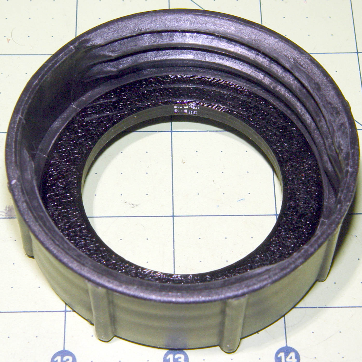
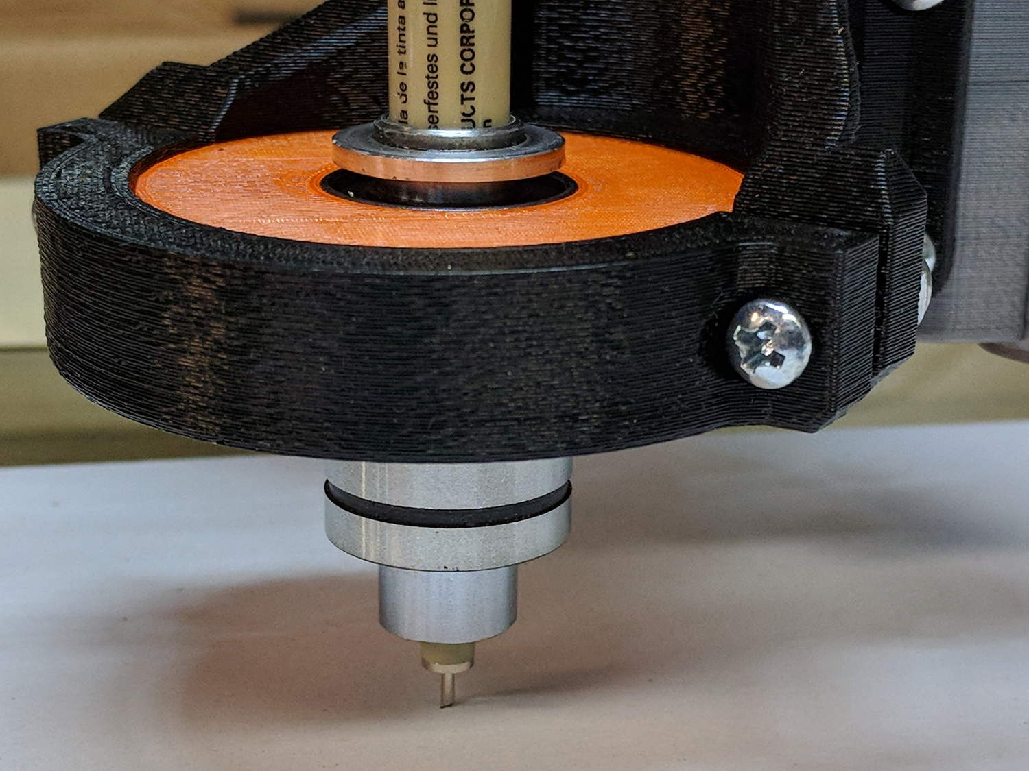
Having a single spring and a fixed upper plate works much better than the first version:

The (lubricated!) nyloc nuts under the plate provide a little friction and stabilize the whole affair.
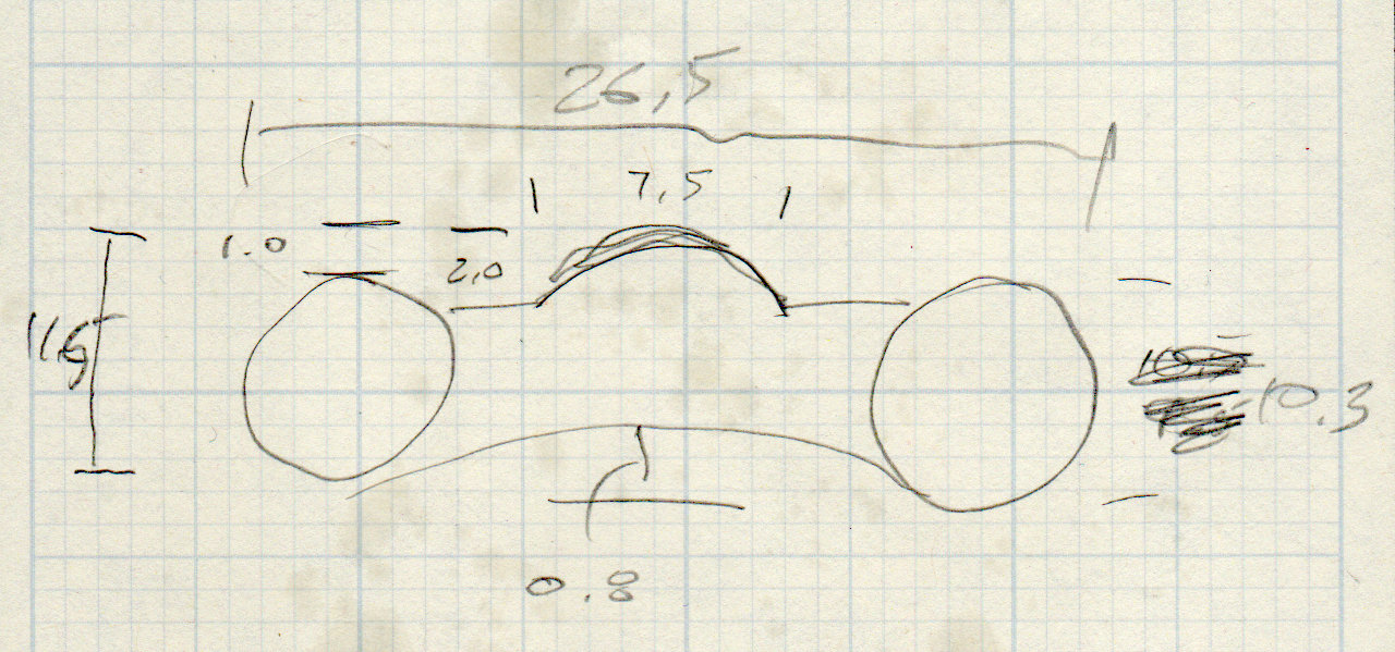
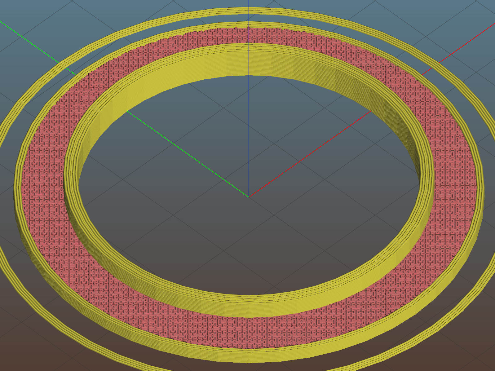
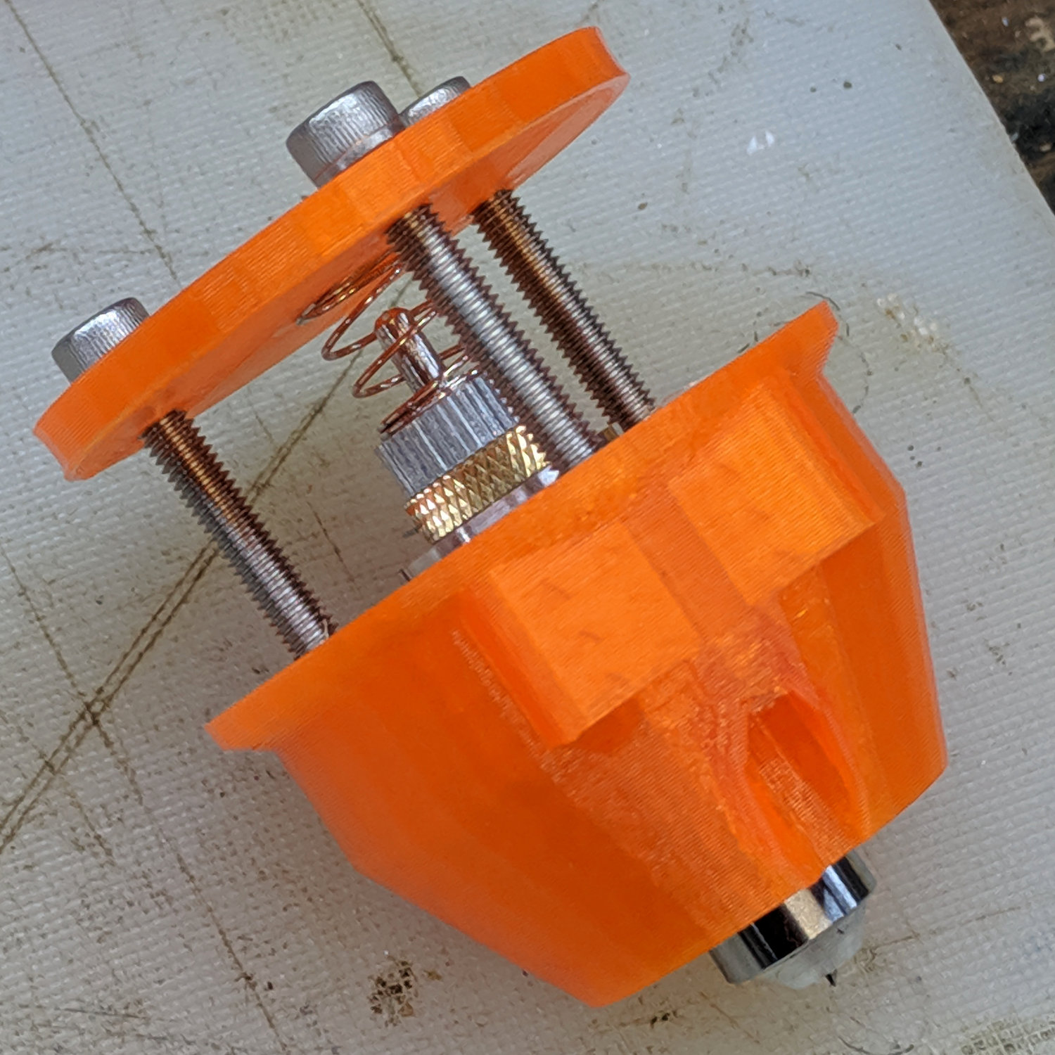
The solid model has the same stylin’ tapered snout as the LM12UU drag knife mount:
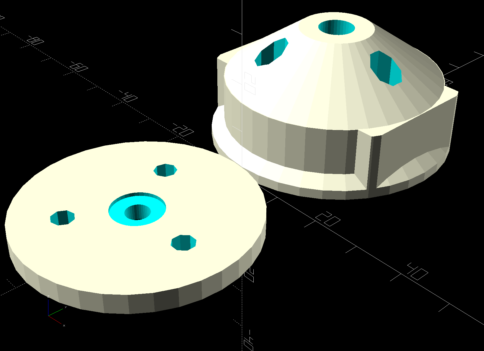
The spring seats in the plate recess, with the 3 mm shank passing through the hole as the tool holder presses the tip against the workpiece.
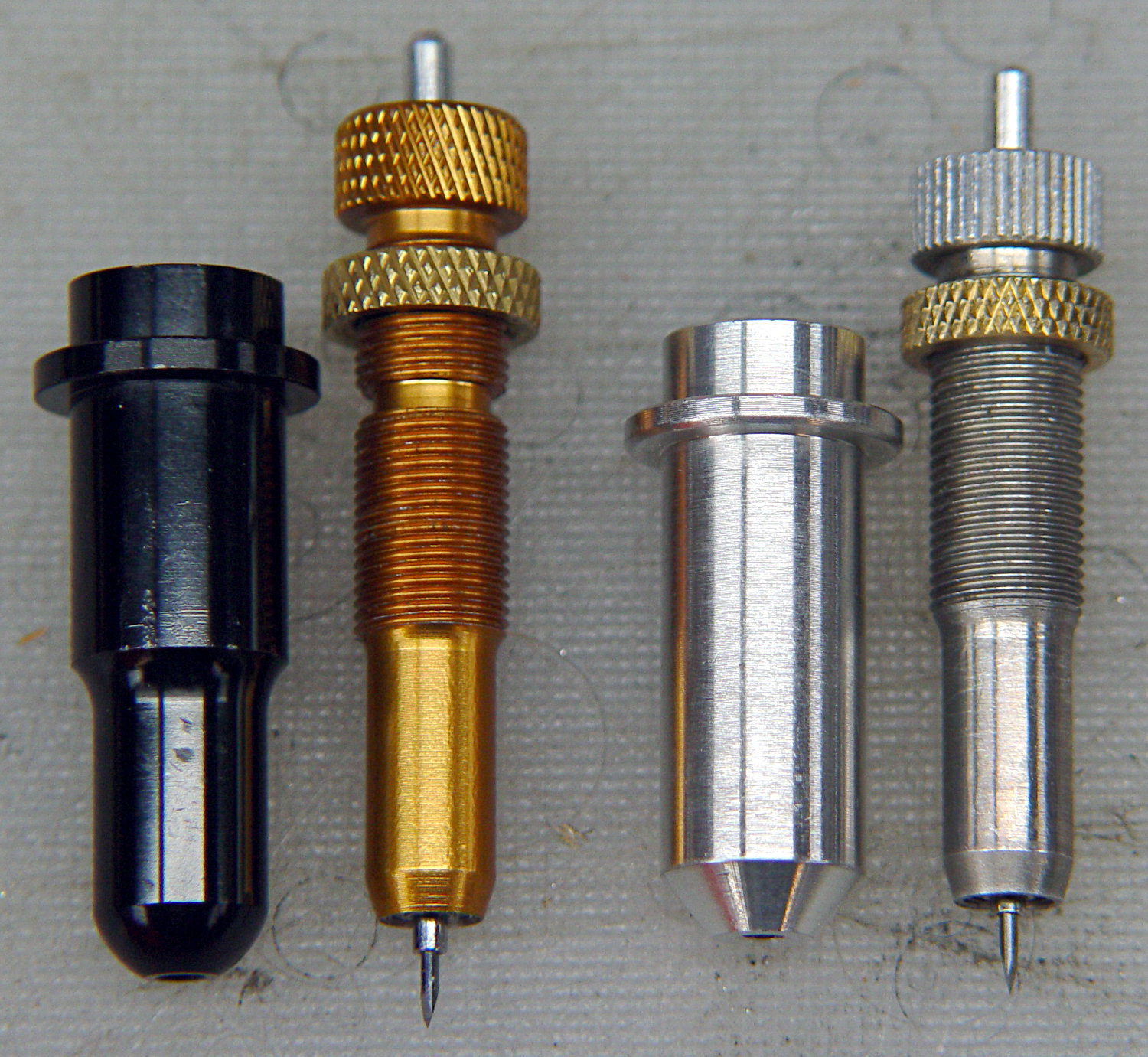
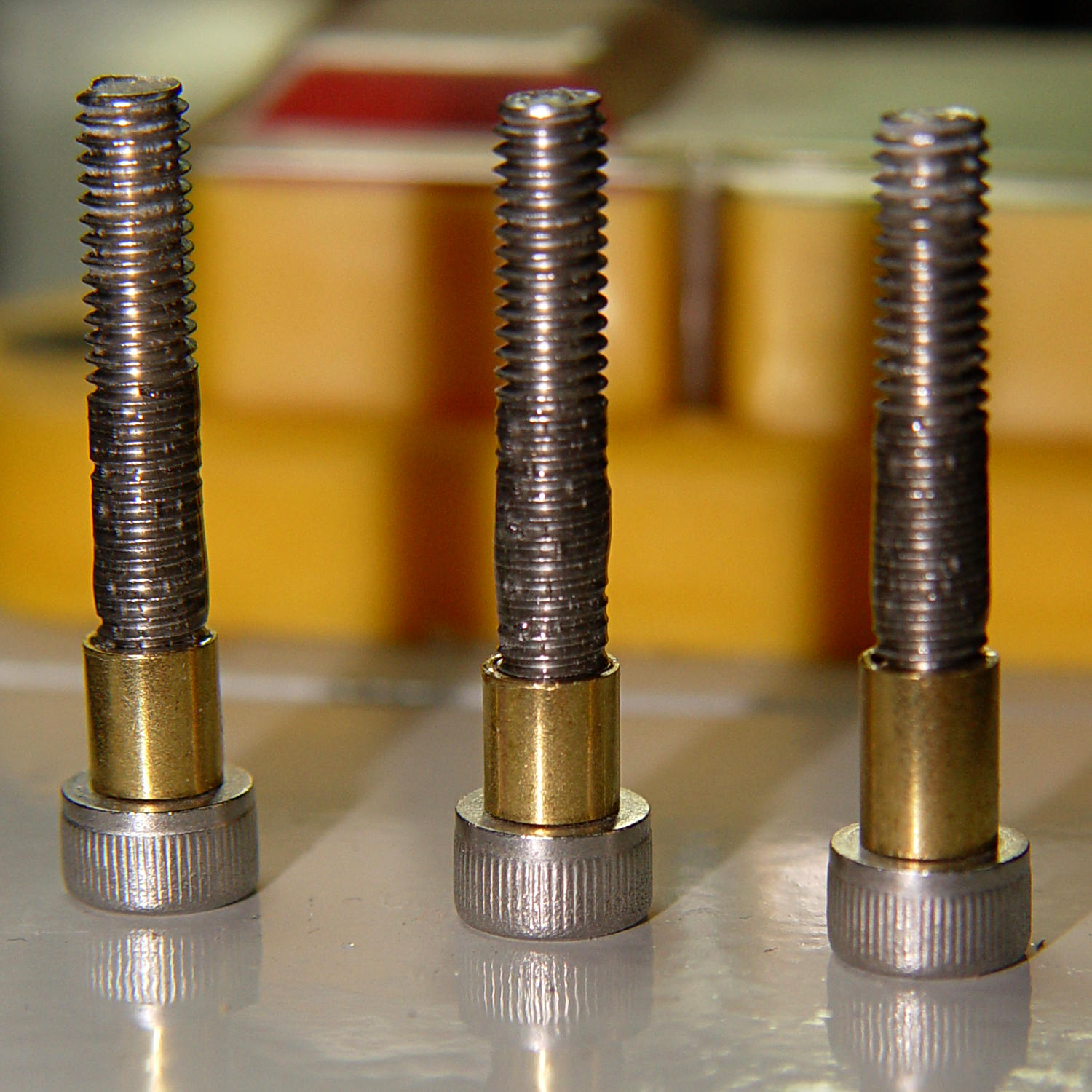
I diamond-filed a broken carbide end mill to make a slotting tool:
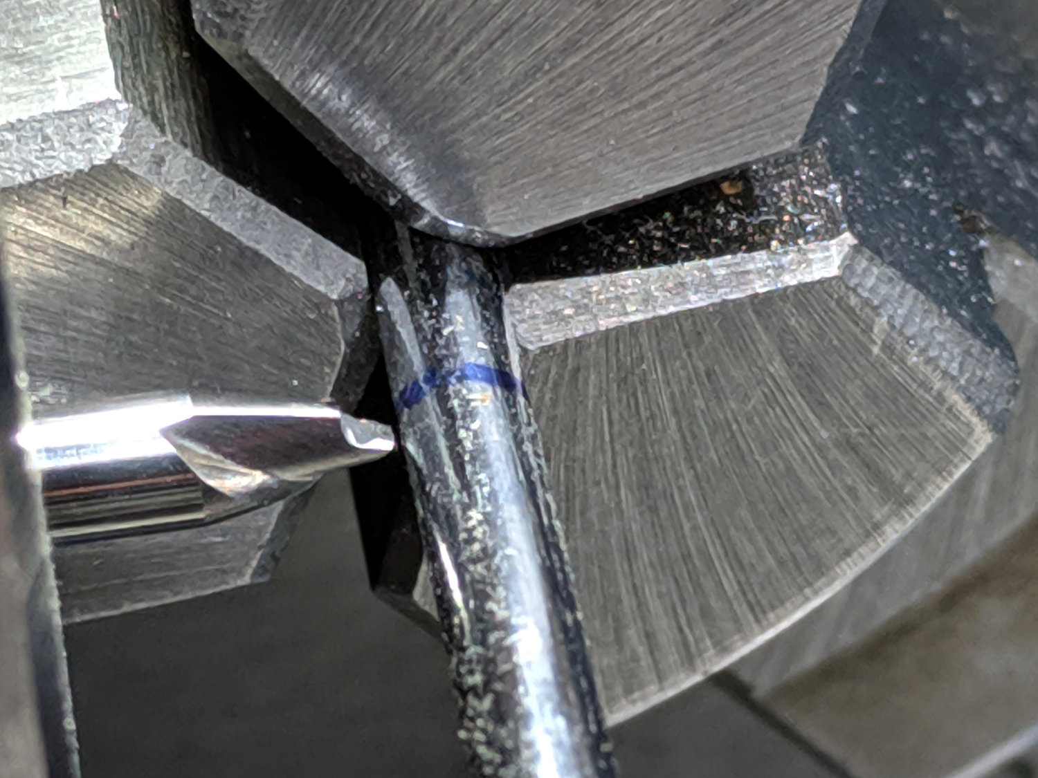
Lacking any better method (“a tiny clip spreader tool”), I rammed the Jesus clip the length of the shank with a (loose-fitting) chuck in the tailstock:

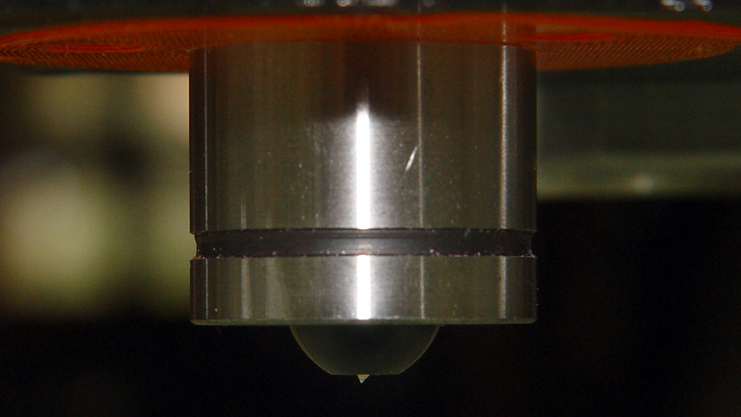
Even without nyloc nuts, the first test worked fine:
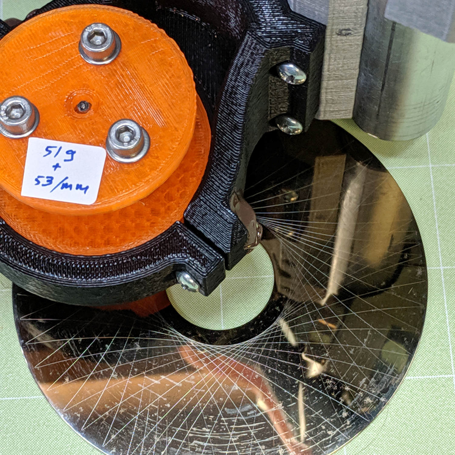
The 53 g/mm spring rate may be too low for serious engraving, but it suffices for subtle Guilloché patterns on scrap platters.
The OpenSCAD source code as a GitHub Gist:
| // Drag Knife Holder using LM12UU linear bearing | |
| // Ed Nisley KE4ZNU – 2019-04-26 | |
| // 2019-05-09 LM3UU for diamond scribe | |
| // 2019-05-28 taper end, single spring around shaft | |
| Layout = "Build"; // [Build, Show, Puck, Mount, Plate] | |
| /* [Extrusion] */ | |
| ThreadThick = 0.25; // [0.20, 0.25] | |
| ThreadWidth = 0.40; // [0.40, 0.40] | |
| /* [Hidden] */ | |
| Protrusion = 0.1; // [0.01, 0.1] | |
| HoleWindage = 0.2; | |
| inch = 25.4; | |
| function IntegerMultiple(Size,Unit) = Unit * ceil(Size / Unit); | |
| ID = 0; | |
| OD = 1; | |
| LENGTH = 2; | |
| //- Adjust hole diameter to make the size come out right | |
| module PolyCyl(Dia,Height,ForceSides=0) { // based on nophead's polyholes | |
| Sides = (ForceSides != 0) ? ForceSides : (ceil(Dia) + 2); | |
| FixDia = Dia / cos(180/Sides); | |
| cylinder(r=(FixDia + HoleWindage)/2,h=Height,$fn=Sides); | |
| } | |
| //- Dimensions | |
| // Knife holder & suchlike | |
| KnifeBody = [3.0,9.0,2.0]; // washer epoxied to diamond shaft, with epoxy fillet | |
| Spring = [9.5,10.0,3*ThreadThick]; // compression spring around shaft, LENGTH = socket depth | |
| WallThick = 4.0; // minimum thickness / width | |
| Screw = [4.0,8.5,8.0]; // holding it all together, OD = washer | |
| Insert = [4.0,6.0,10.0]; // brass insert | |
| Bearing = [3.0,7.0,2*10.0 + WallThick]; // linear bearing body (pair + small gap) | |
| // Basic shape of DW660 snout fitting into the holder | |
| // Lip goes upward to lock into MPCNC mount | |
| Snout = [44.6,50.0,9.6]; // LENGTH = ID height | |
| Lip = 4.0; // height of lip at end of snout | |
| Plate = [KnifeBody[ID],Snout[OD] – WallThick,WallThick]; // spring reaction plate | |
| PuckOAL = max(Bearing[LENGTH],(Snout[LENGTH] + Lip)); // total height of DW660 fitting | |
| echo(str("PuckOAL: ",PuckOAL)); | |
| Key = [Snout[ID],25.7,(Snout[LENGTH] + Lip)]; // rectangular key | |
| NumScrews = 3; | |
| ScrewBCD = 2.5*(Bearing[OD]/2 + Insert[OD]/2 + WallThick); | |
| NumSides = 9*4; // cylinder facets (multiple of 3 for lathe trimming) | |
| module DW660Puck() { | |
| translate([0,0,PuckOAL]) | |
| rotate([180,0,0]) { | |
| cylinder(d=Snout[OD],h=Lip/2,$fn=NumSides); | |
| translate([0,0,Lip/2]) | |
| cylinder(d1=Snout[OD],d2=Snout[ID],h=Lip/2,$fn=NumSides); | |
| cylinder(d=Snout[ID],h=(Snout[LENGTH] + Lip),$fn=NumSides); | |
| translate([0,0,(Snout[LENGTH] + Lip) – Protrusion]) | |
| cylinder(d1=Snout[ID],d2=2*WallThick + Bearing[OD],h=PuckOAL – (Snout[LENGTH] + Lip),$fn=NumSides); | |
| intersection() { | |
| translate([0,0,0*Lip + Key.z/2]) | |
| cube(Key,center=true); | |
| cylinder(d=Snout[OD],h=Lip + Key.z,$fn=NumSides); | |
| } | |
| } | |
| } | |
| module MountBase() { | |
| difference() { | |
| DW660Puck(); | |
| translate([0,0,-Protrusion]) // bearing | |
| PolyCyl(Bearing[OD],2*PuckOAL,NumSides); | |
| for (i=[0:NumScrews – 1]) // clamp screws | |
| rotate(i*360/NumScrews) | |
| translate([ScrewBCD/2,0,-Protrusion]) | |
| rotate(180/8) | |
| PolyCyl(Insert[OD],2*PuckOAL,8); | |
| } | |
| } | |
| module SpringPlate() { | |
| difference() { | |
| cylinder(d=Plate[OD],h=Plate[LENGTH],$fn=NumSides); | |
| translate([0,0,-Protrusion]) // ample shaft clearance | |
| PolyCyl(1.5*KnifeBody[ID],2*PuckOAL,NumSides); | |
| // translate([0,0,Plate[LENGTH] – KnifeBody[LENGTH]]) // flange, snug fit | |
| // PolyCyl(KnifeBody[OD],KnifeBody[LENGTH] + Protrusion,NumSides); | |
| translate([0,0,Plate[LENGTH] – Spring[LENGTH]]) // spring retainer | |
| PolyCyl(Spring[OD],Spring[LENGTH] + Protrusion,NumSides); | |
| for (i=[0:NumScrews – 1]) // clamp screws | |
| rotate(i*360/NumScrews) | |
| translate([ScrewBCD/2,0,-Protrusion]) | |
| rotate(180/8) | |
| PolyCyl(Screw[ID],2*PuckOAL,8); | |
| } | |
| } | |
| //—– | |
| // Build it | |
| if (Layout == "Puck") | |
| DW660Puck(); | |
| if (Layout == "Plate") | |
| SpringPlate(); | |
| if (Layout == "Mount") | |
| MountBase(); | |
| if (Layout == "Show") { | |
| MountBase(); | |
| translate([0,0,1.5*PuckOAL]) | |
| rotate([180,0,0]) | |
| SpringPlate(); | |
| } | |
| if (Layout == "Build") { | |
| translate([0,Snout[OD]/2,PuckOAL]) | |
| rotate([180,0,0]) | |
| MountBase(); | |
| translate([0,-Snout[OD]/2,0]) | |
| SpringPlate(); | |
| } |