Being in need of small bins to sort cutoffs / scrap material from the laser and now having an essentially unlimited supply of corrugated cardboard at hand, this made some sense:
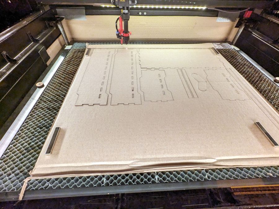
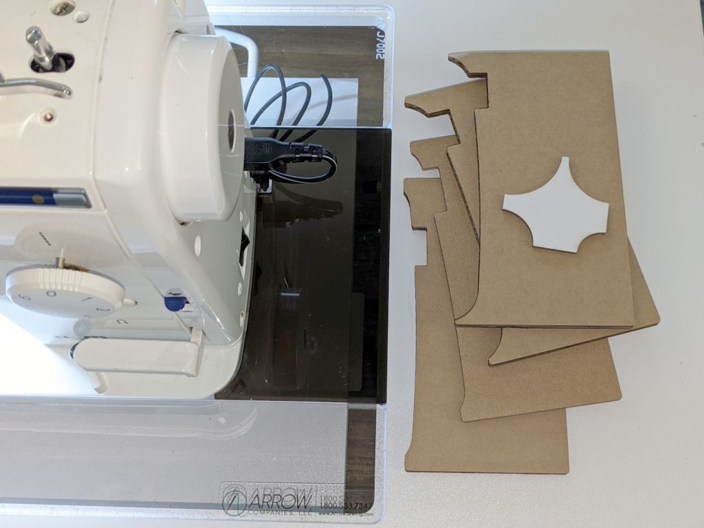
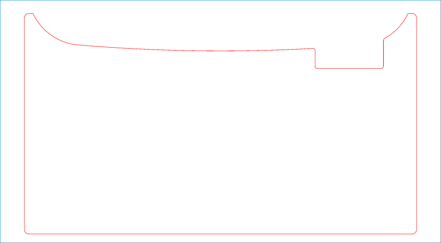
The cardboard is 3.8 mm thick and laid with the ribs parallel to the X axis to make all the parts stiff in the right direction. I rearranged the parts to fit the space available and work around the butterfly finger hole over on the right.
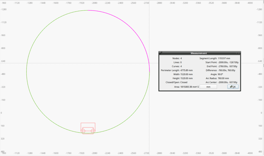
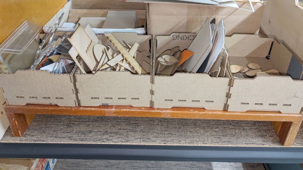
The box pattern comes from the infinite supply at boxes.py (you’re welcome to the jawbreaker URL with my parameters) and assembles to become a sturdy little box:

Rather than gluing all those fingers into their holes, I ran a hot melt glue bead around the bottom perimeter and up the four corners, which seems to do the trick. The fingers parallel to the X axis tend to be fragile, as only one or two corrugated ribs run along their length, but the overall box is surprisingly rigid after gluing.
They’re nominally stackable and the pattern includes stiffeners glued across the leg openings so they don’t slide off the box below, but it’s obvious these boxes will always have too much stuff to allow stacking.
I made a longer box for plywood scraps and may need a couple more for other stuff yet to be unpacked, but you get the general idea.
The WordPress AI Assistant reminds me to remind you of the safety measures appropriate for using hot melt glue: consider yourself warned.