Ed Nisley's Blog: Shop notes, electronics, firmware, machinery, 3D printing, laser cuttery, and curiosities. Contents: 100% human thinking, 0% AI slop.
Category: Software
General-purpose computers doing something specific
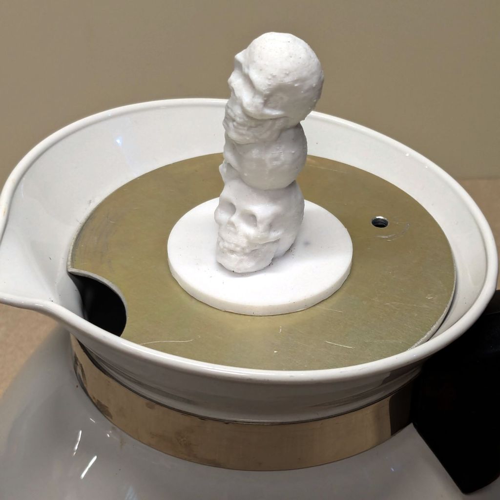
Long years ago, the Bakelite (or some such) lid on our rarely used teapot disintegrated, whereupon I replaced it with an aluminum sheet and metal knob. Admittedly, a metal knob was not the brightest idea I ever had, but it sufficed for a few uses over the intervening decades.
Mary hosted this month’s quilting bee and, after having someone else bring a larger teapot for the occasion, suggested I Make. A. Better. Knob. After a bit of searching, this statue seemed appropriate for the season:
Skull teapot knob
It’s printed with PETG filament that should easily withstand the no-more-than-boiling-water temperatures found atop a teapot.
I imported the original model into PrusaSlicer, shrank it to 50 mm tall and simplified the mesh, exported it as an OBJ file, imported it into OpenSCAD, mashed it together with a 1/4-20 threaded_nut from BOSL2, added the finger protector, and got a suitable model:
Teapot Knob – solid model bottom view
The as-printed threads were a bit snug with $slop=0, but running the screw in with a dot of silicone grease to ease the way worked fine.
I should rebuild the whole lid in PETG-CF sometime.
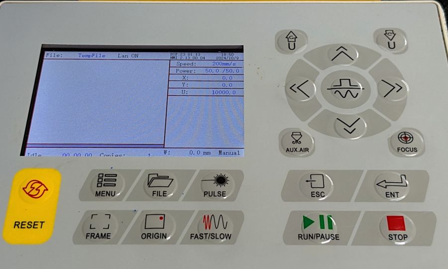
The Ruida KT332N controller on my OMTech laser cutter has two settings affecting the final position of the U axis (which controls the platform’s position) after pushing the Focus button on the machine console:
KT332N Laser Controller display
After turning the machine on or pressing the Reset button, the U axis does not automatically home and reports its position as 1000 mm. This allows manual control in either direction with the U↑ and U↓ buttons.
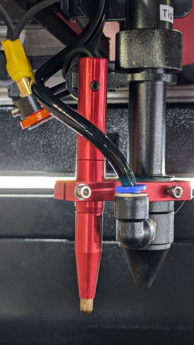
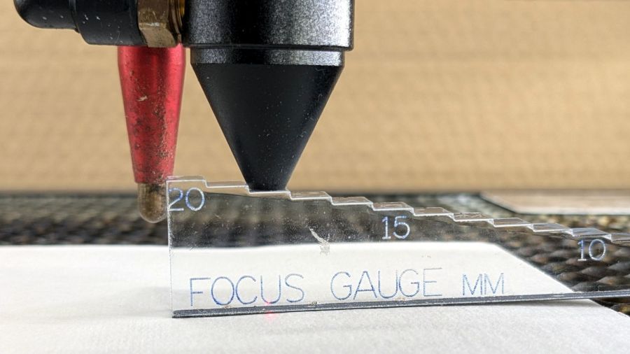
Pushing the Focus button (then confirming the action by pressing the Ent⏎ button) causes the controller to raise the platform until the focus “pen” (which is really a switch) trips, presumably on the material you intend to cut / engrave. This picture shows the pen and its attachment to the laser nozzle:
OMTech laser focus pen-switch
The pen’s position in its clamp has no relation to the laser beam focal point below the nozzle: loosening either of the clamp screws lets you move the pen vertically. You must tell the controller how much to move the platform after the switch trips to properly set the focus, which means you must measure that distance. More on that later.
The vertical position of the platform when the “pen” switch trips is its Home position. The controller then lowers the platform by the distance in the Home Offset setting and defines that position as U = 0.0 mm.
The Home Offset can be zero:
KT332N Home Offset Setting
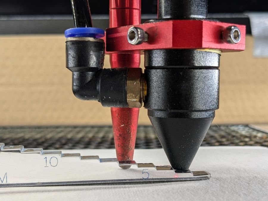
In which case the platform does not move after the switch trips:
Focus step gauge – 3 mm
The step gauge shows the nozzle is 3.0 mm above the material (the first step is 2 mm, because a 1 mm acrylic tab is crazy talk) when the switch trips. Although you can’t quite see the switch plunger through the gauge, it has about 5 mm of travel before tripping, which means it’s firmly pressed against the material and you must not move the nozzle in X or Y to avoid scraping the plunger across the material.
Setting Home Offset to 15.0 mm lowers the platform by 15 mm after the switch trips, putting the nozzle 18 mm above the material:
Focus step gauge – 18 mm
You can (and I have) set the Home Offset so the platform lowers by exactly enough to put the focused beam at the top of the material: push the Focus button and the machine automatically focuses on the material and sets U=0.0 mm at that level.
Unfortunately, the controller will subsequently not move the platform above that position, corresponding to U axis coordinates below zero. That means you (well, I) cannot move the platform upward to put the focus point into the material, as is sometimes required for a good cut through thicker material.
The Focus Distance setting defines an additional distance from wherever the Home Offset leaves the platform:
KT332N Focus Distance Setting
It’s not 15 mm, because I was fiddling with the focus.
That value will position the platform 16 mm below the switch trip point. Because Home Offset = 0.0 sets the U axis coordinate to zero at the trip point, the U axis will be at 16 mm when the platform stops moving.
The key difference is that the controller will now allow the platform to move upward, with decreasing U axis coordinates, until it reaches the switch trip position at U=0. The last 5 mm of travel will occur with the switch actuator pressing against the material, so it’s pretty much useless for actual cutting or engraving.
So I think the way to go involves setting:
Home Offset to the 5-ish mm required for full switch release
Focus Distance to the remaining 10-ish mm with the focal point on the material surface
I hadn’t done that before, because I hadn’t thought this through.
The Home Offset depends only on the switch travel before it actuates and won’t change when (not if) the pen position changes with respect to the nozzle.
The Focus Distance defines the additional travel for proper focus at the material surface, so that’s where all the variations due to pen position will go. Unfortunately, that distance cannot be directly measured, because it corresponds to the difference between two positions.
Being an Old Guy, I lift dumbbell weights after bike rides for load-bearing upper-body exercise, but need a few more dumbbell nuts (a.k.a. “collars”) to simplify adjusting the weights for each set. Such things are commercially available, but the reviews suggest abysmally bad thread QC and a high return rate.
Given that I treat my toys carefully, this should suffice:
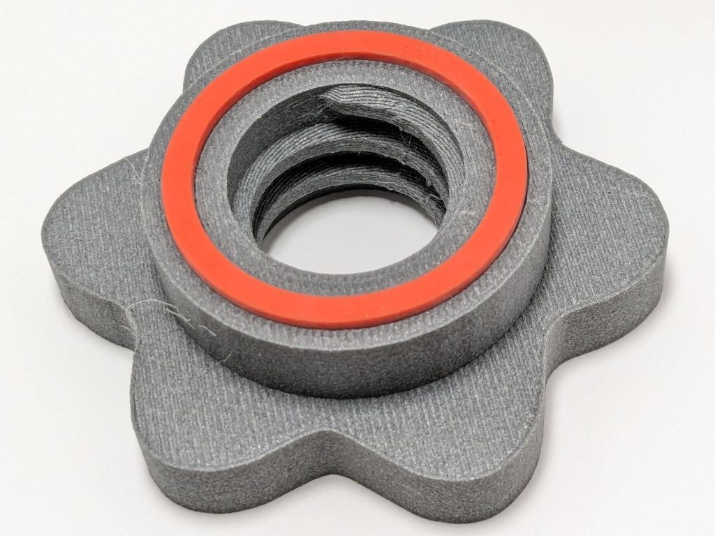
Dumbbell Nut – finished
Start with a scan of a steel nut in GIMP:
Dumbbell Nut – scan
Blow out the contrast, trace it, smooth out some irregularities, get a mask:
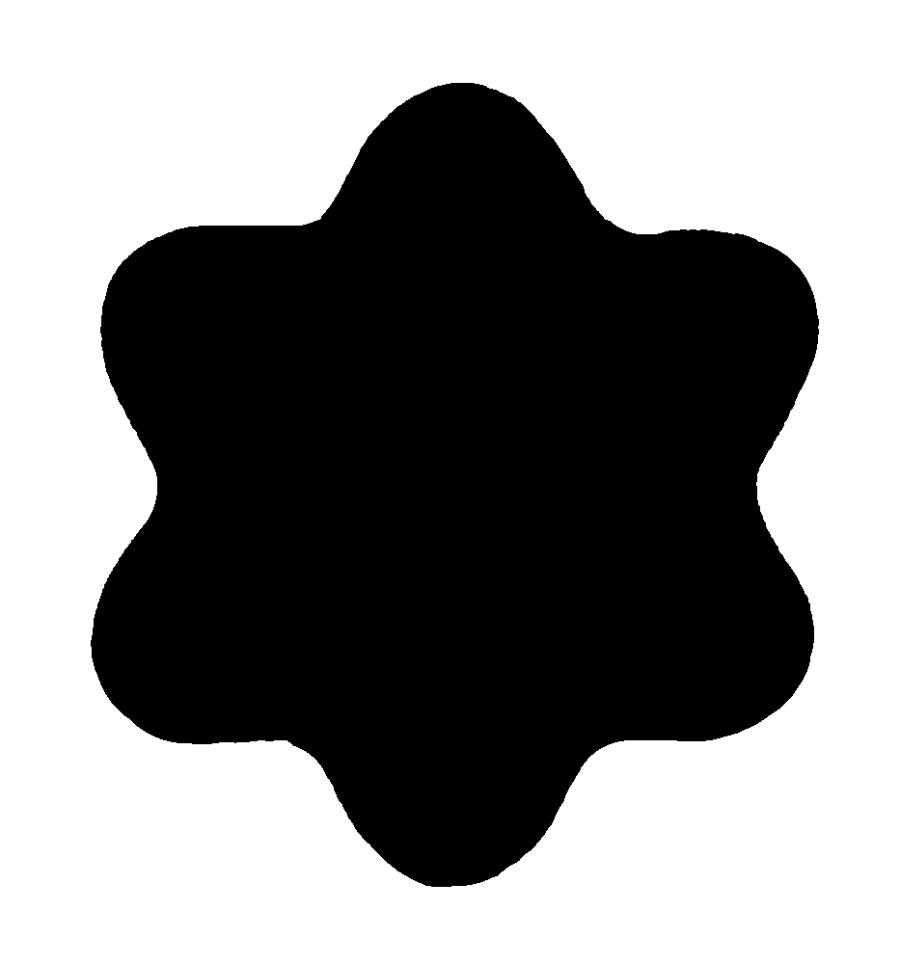
Dumbbell Nut – mask
Select by color, convert the selection to a path, save as SVG, import into OpenSCAD, add a nut with threads from the incomparably useful BOSL2 library, extrude a few features, and this pops out:
Dumbbell Nut – solid model
Run it through PrusaSlicer, print on the MK4, and iterate a few times to get everything right:
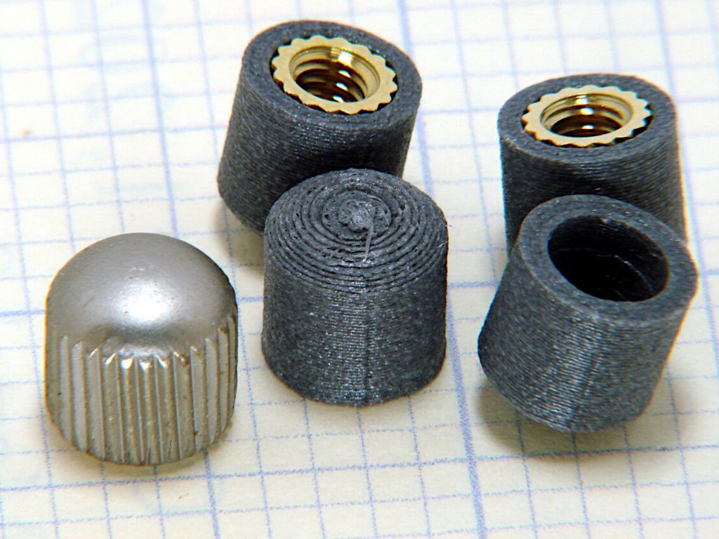
Dumbbell Nut – test pieces
I naively thought the threads were something standard like Acme, but they’re full-frontal custom trapezoidal. I knew the first pass would be wrong, so the small hex nut on the left started the whole process. Upper left is a revised Acme thread with all the other features, lower middle is the custom trapezoidal thread, and the nut on the upper right worked. Make three more, just like the first one, enjoying the magic of 3D printing.
Draw the bumper washer in LightBurn based on the dimensions in the OpenSCAD code, cut a set from stamp-pad rubber & adhesive sheet, then assemble:
Dumbbell Nut – assembly
As the saying goes, we got nuts:
Dumbbell Nut – installed
The gray PETG-CF looks black against a white background and gray against black iron.
With a set of precisely fitting nuts in hand, I discovered one of the four bars in my weight sets is slightly larger than the others, so the code now produces an embiggened root diameter and I have two spares.
The garden hose leading from the standpipe / hose bibs outside Mary’s garden to her drip irrigation plumbing has an octagonal fitting requiring more torque than her hand can easily produce. I offered to make a larger grip for the fitting, which amounts to a disk with a grippy rim sized to her hand and an interior opening suitable for gluing to the fitting.
A couple of laser-cut MDF sizing prototypes accompanied me to the garden:
Hose Fitting Grip – MDF prototype
The springy fingers around the fitting soak up the inevitable distortions found in a battered hose and will eventually be filled with adhesive to lock the grip in place.
MDF being obviously the wrong material for a permanent installation, the final grip will be 3D printed, with the LightBurn layout modified to produce the internal structure:
Hose Fitting Grip – LightBurn layers
From left to right:
The stacked pieces in order of printing
Main grip with springy fingers
Spacer keeping the fingers away from the narrower opening
Support layer
Narrow opening to align the grip with the end of the fitting
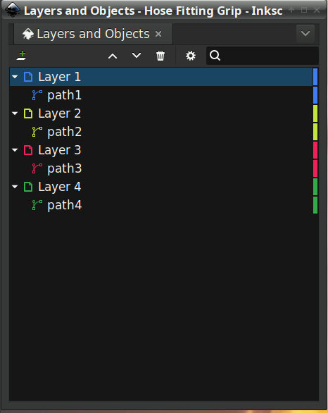
Exporting the SVG images and making a bank shot off Inkscape to create layer names:
Hose Fitting Grip – Inkscape layers
The ascending layer name + numbers allow a simple OpenSCAD program to extract the SVG shapes by name, extrude them to the proper thickness, put them at the proper height, then combine the result:
The hideous mess generating the Level vector happens because OpenSCAD does not have mutable variables and I hate retyping numbers. One can use a recursive function to add the values, but copypasta makes more sense in this case.
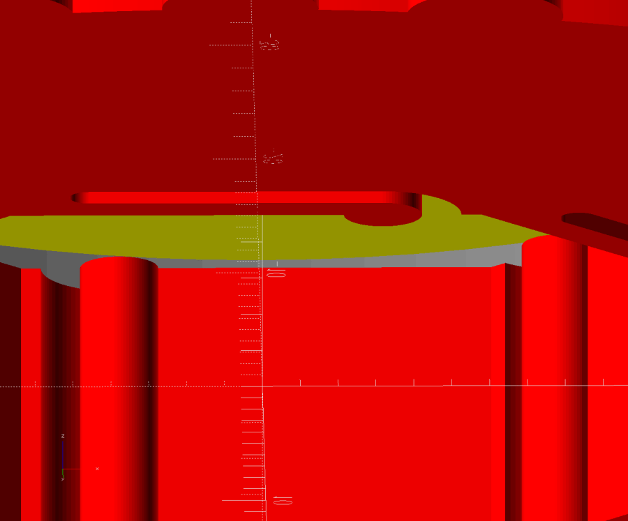
Which produces this solid model, with garish colors for pedagogic purposes:
Hose Fitting Grip – top – solid model
The thin yellow band will be one thread thick to provide support for the green layer with a smaller ID than the springs below it. The gray layer below the yellow is the air gap above the springs.
Peering inside the bottom shows the (gray) layer providing clearance between the springs and the (yellow) support layer:
Hose Fitting Grip – bottom interior – solid model
Exporting the model as a 3mf file, importing it into PrusaSlicer, and slicing it with suitable parameters (Extrusion Multipler = 0.8) does what you’d expect. This top view shows the internal structure just below the support bridge across the middle:
Hose Fitting Grip – spring detail – PrusaSlicer
Printing it in gray PETG-CF was uneventful, with the bridging layer coming out surprisingly well:
Hose Fitting Grip – as printed
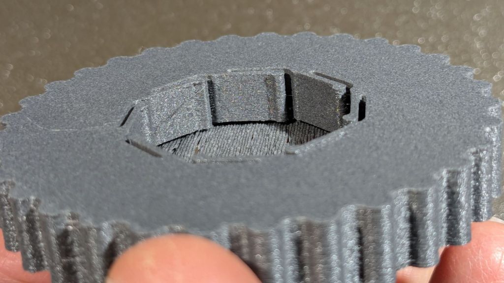
The springs definitely have an air gap in there:
Hose Fitting Grip – printed interior
And the support layer cuts out neatly with an Xacto knife:
Hose Fitting Grip – support removed
We’ve had enough rain over the last few days (something to do with a continental-scale storm) to keep me and my adhesives out of the garden, but it hasn’t needed any watering, either.
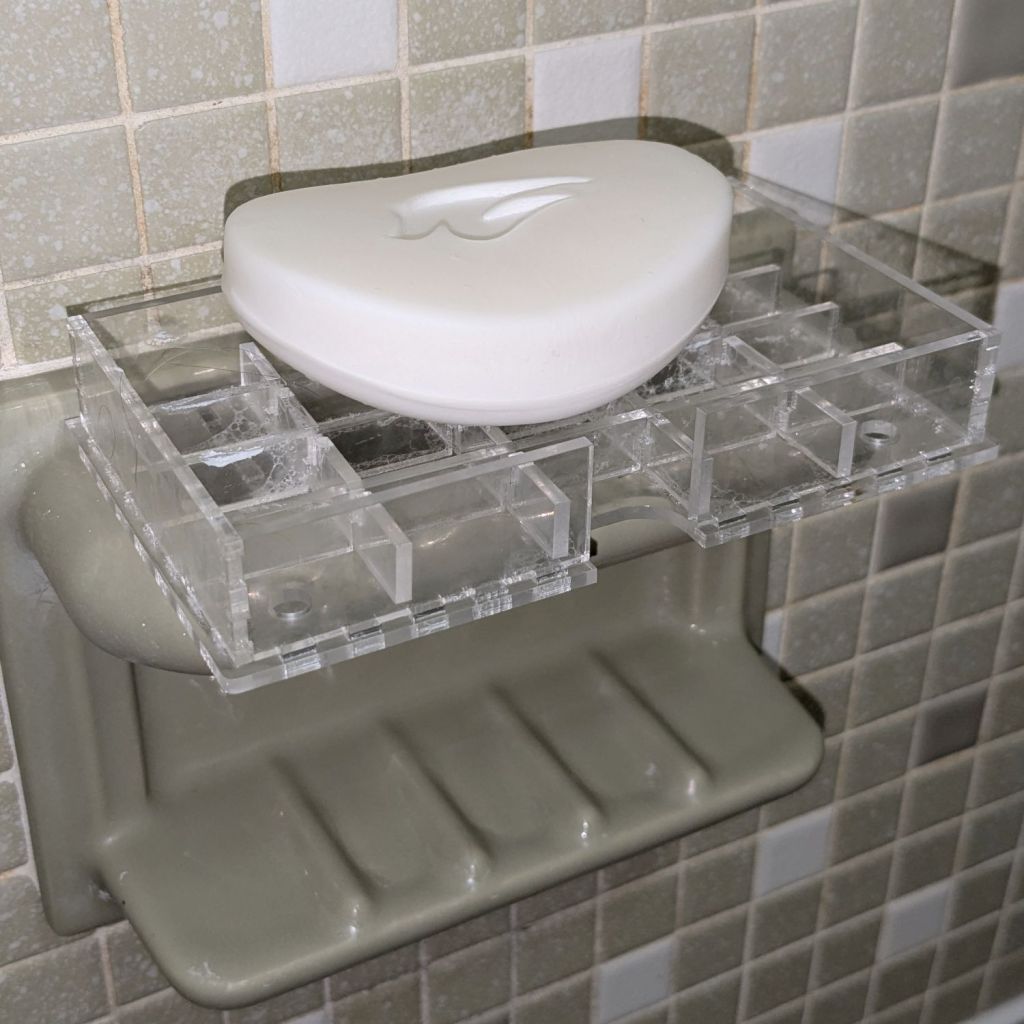
As expected, the adhesive foam strips I used on the bathtub soap tray didn’t survive continued exposure to hot soapy water, so Version 2 includes hooks securing it to the ceramic soap tray and a few other tweaks:
Bathtub Soap Tray – V2 – LightBurn layout
The view from the top:
Soap Tray V2 – top
The hooks are more visible from the bottom, as is the 10 AWG copper wire preventing the whole affair from rotating around the ceramic handle from the weight of the soap bar:
Soap Tray V2 – bottom
Ignore the usual crud you’ll find on your ceramic soap tray, too.
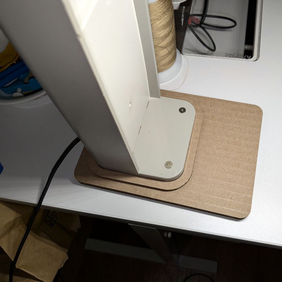
It’s not particularly elegant, what with being cardboard, but it’s a proof of concept that will determine the final size.
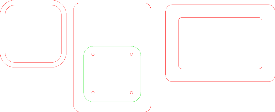
The top layer is a ring around the lamp pedestal for a bit of stabilization protecting the four M3 screws holding the base to the lamp. Those screws sit on a 60 mm square, offset 1 mm to the front of the lamp:
NisLite Baseplate – LightBurn layout
Which explains why I typically make the first few versions of anything out of cardboard.
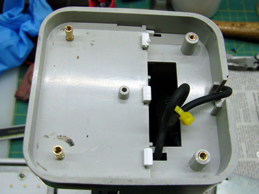
For the record, those inserts look like this:
Converted Ottlite – brass inserts
A pair of very flat-head M3 screws hold the front inserts in place through holes match-drilled in the remains of the bosses I’d long ago epoxied in place. I pressed the rear inserts in place by misusing the drill press, as the lamp is much too tall for the heat setter.
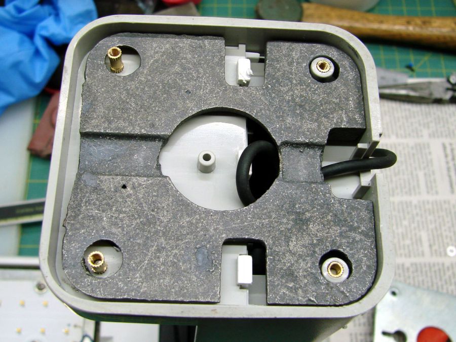
Then comes the iron base weight:
Converted Ottlite – iron weight
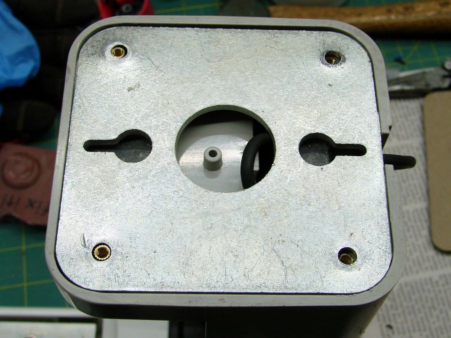
And then the steel outer plate:
Converted Ottlite – steel cover plate
The new base plate gets a ring around its perimeter for clearance under the four pan head M3 screws into the inserts.
If the cardboard base is stable enough, we’ll do an acrylic version in cheerful primary colors.
The LightBurn layout in SVG format as a GitHub Gist:
While cleaning dead bugs out of the ceiling lamps, we discovered the kitchen light was missing one of the three nuts holding its cover in place. While spare nuts might be available, this seemed like a quicker & easier solution:
Ceiling Lamp Nut – bottom view – solid model
The stepped interior fits a brass insert with 8-32 threads (not metric, to my utter astonishment) rammed in place with a heat-set tool:
Ceiling Lamp Nut – insert staking
Using the nominal diameters seems to work fine, although I’m sure some finesse will be needed with smaller inserts.
Printed four just to be sure, rammed three inserts, and they’re ready:
Ceiling Lamp Nuts – as-built
The curved cap matches the original nut through the use of the Chord Equation to get the cap radius as a function of its height (sagitta) & base diameter. Admittedly, it looks kinda grotty with only a dozen layers, but it’s the thought that counts.
The original nuts are heavy knurled steel and the new ones are cheap plastic, but nobody will ever know:
Ceiling Lamp Nut – installed
Bonus: now I have two spare steel nuts for the next time …


