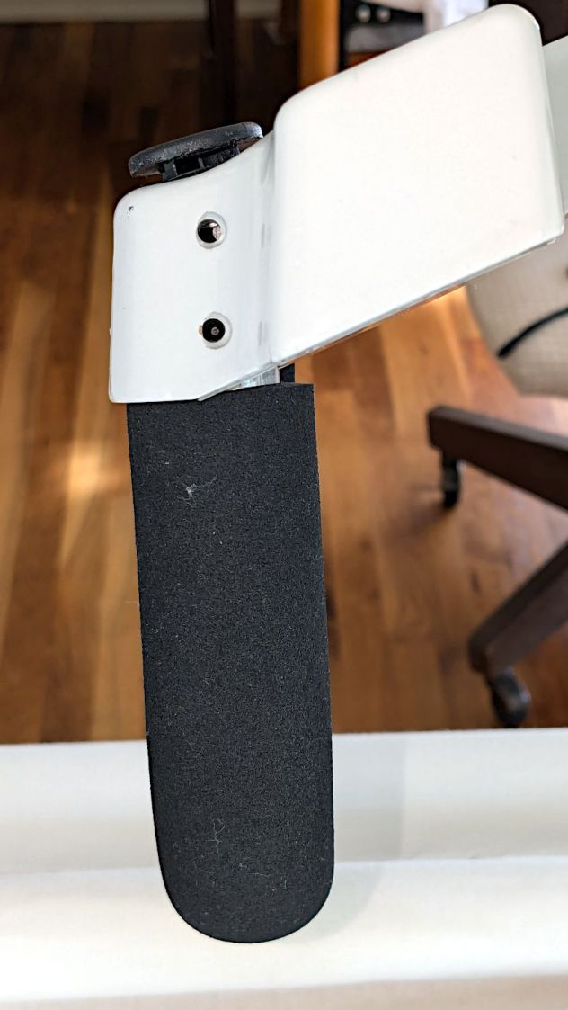
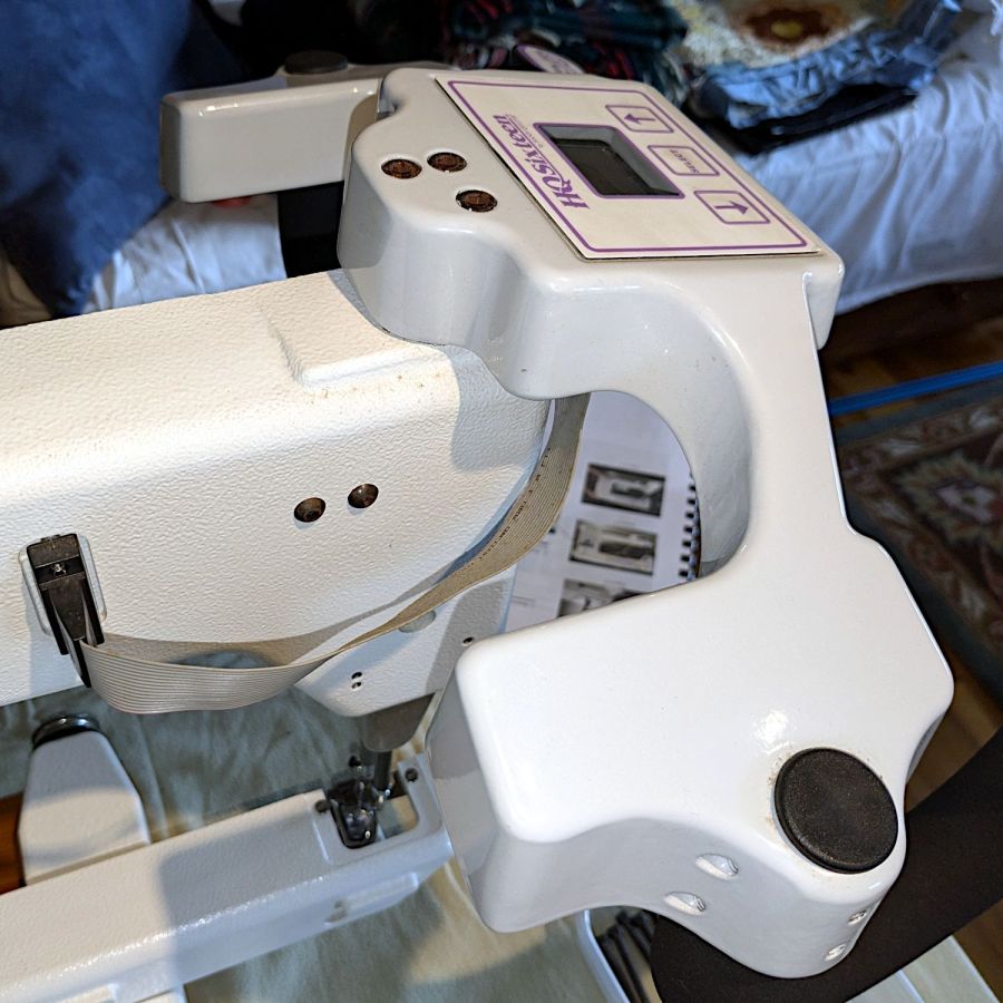
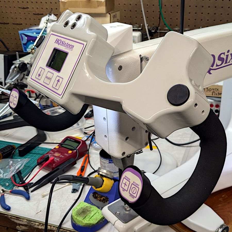
With the handlebar assembly angled to let Mary see the LCD panel, the grips no longer meet her hands at the proper angle:
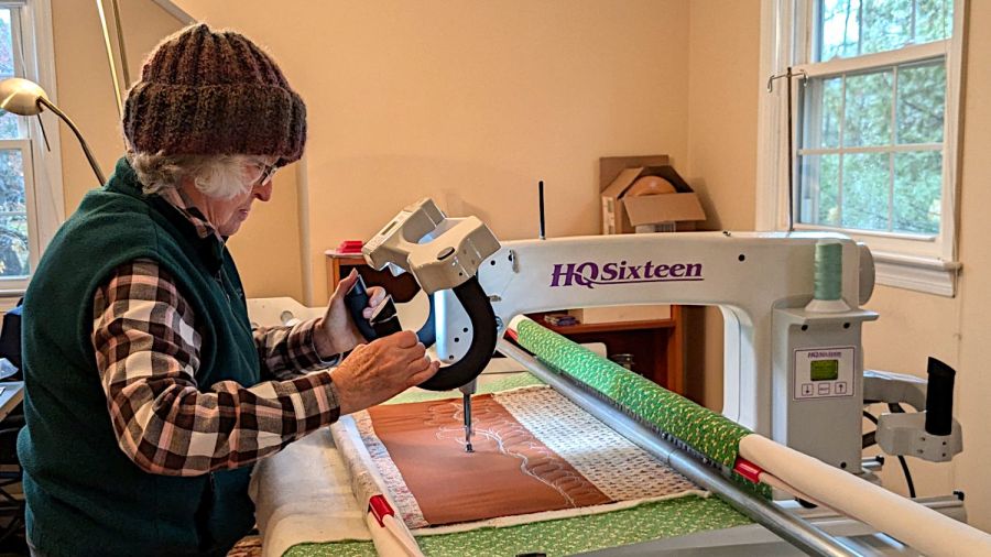
Each grip has two buttons intended for thumb operation, but at that angle her thumbs lack oomph.
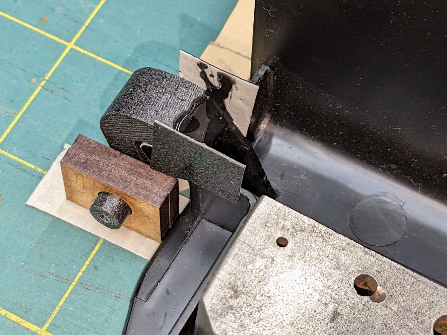
So I added a compensating angle just under the handlebar control assembly:

Restoring the front part to vertical means she can walk up to the machine, grab the grips at a neutral wrist angle, and start sewing.
Which required several iterations:
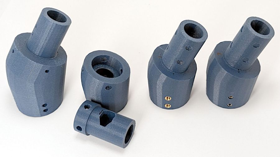
The pictures show various setups as we installed, tried, tweaked, and replaced nearly everything along that progression from left to right. They’re similar, but the details made all the difference.
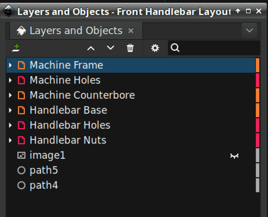
This is an overview of the adapter, with details to follow over the next few days.
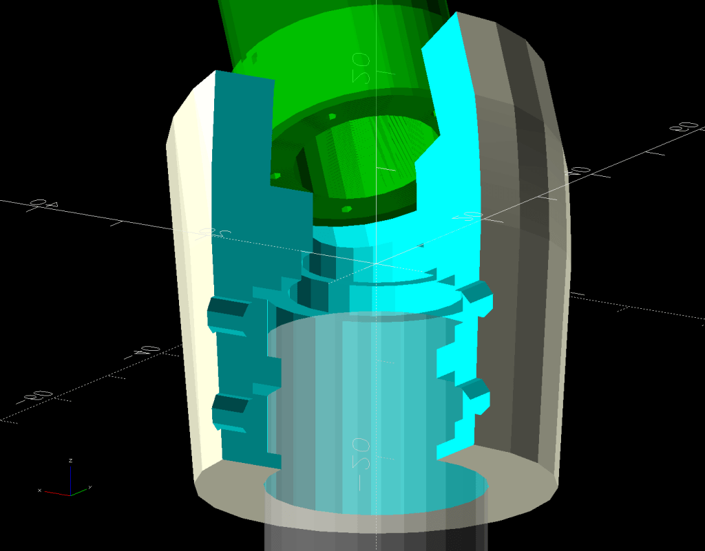
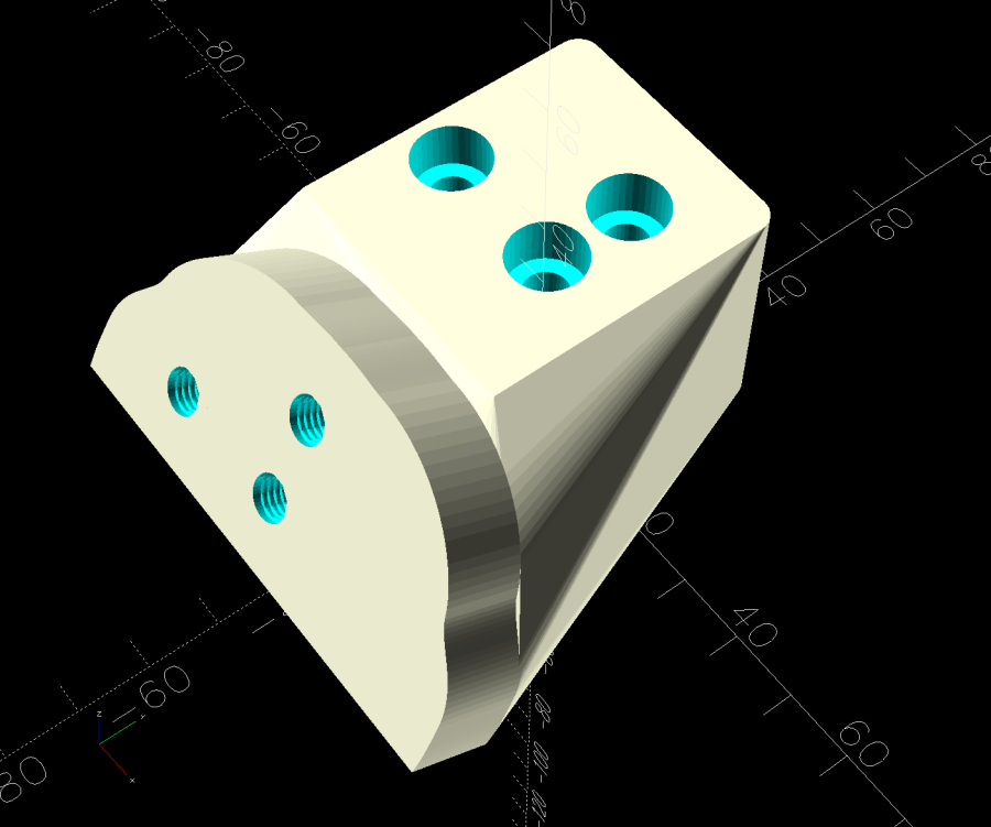
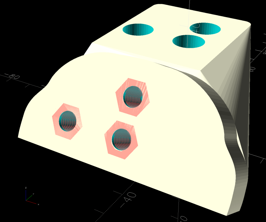
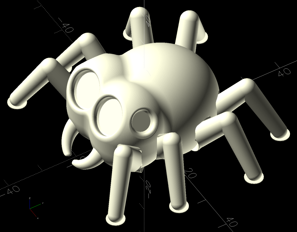
The solid model shows how the pieces go together:
The white chip on top fills the space between the surface of the base and the top of the plug, with some lettering just for pretty.
The greenish plug (not its real color!) sticks into the handlebar control base, where its dimples capture four setscrews. The original grips extended only halfway into the base, leaving the top pair of tapped setscrew holes empty:
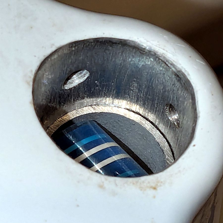
The ribbon cable carries signals from the pushbuttons into the base assembly:
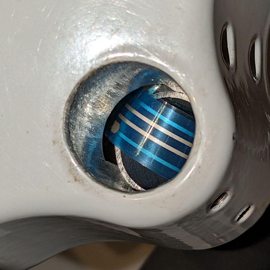
Looks like a guillotine to me, too, but the foam rubber cover prevents the grips from sliding any further into the base:
Despite the metric socket head cap screws used elsewhere on the machine, those are 10-32 setscrews. Took me a while to figure that out, as 10-32 setscrews are visually indistinguishable from M5 setscrews, but neither screw will thread into the other’s nuts even though their wrenches are equally sloppy fits in the other screw.
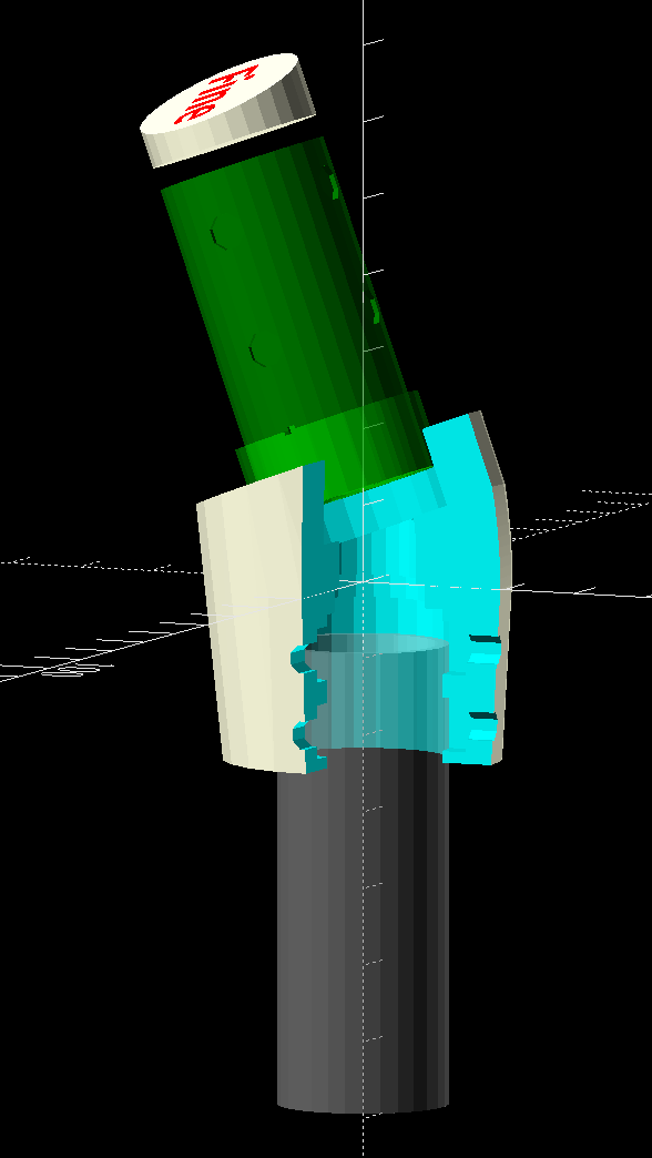
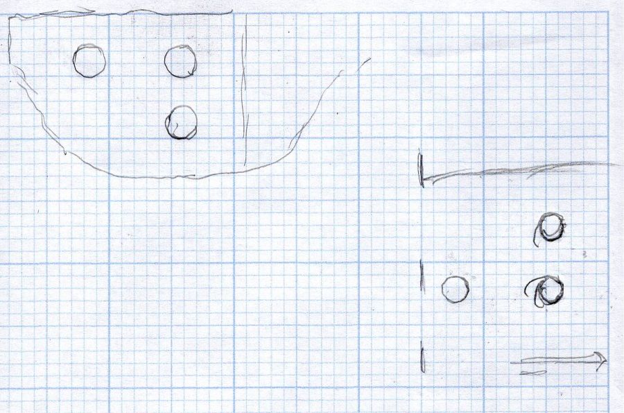
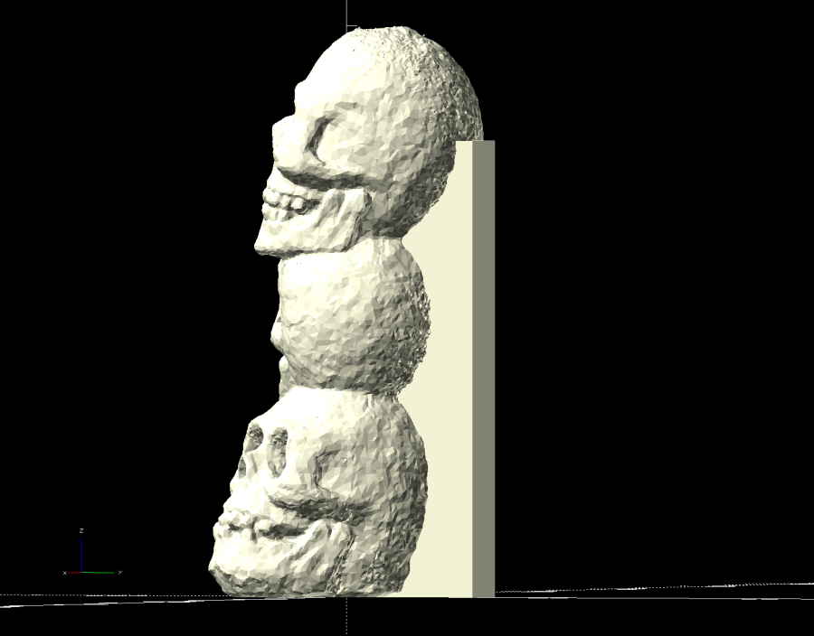
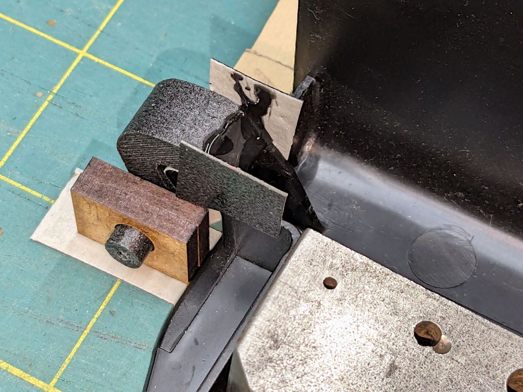
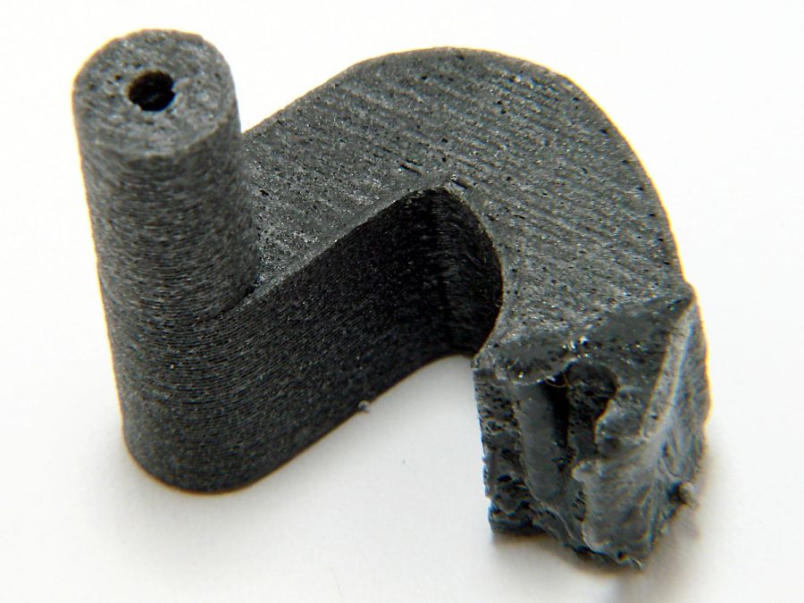
The angle adapter block has an intricate geometry:

Because I don’t know the proper angle, the OpenSCAD model includes enough trig to adjust from 10° to 30°, with the default at 20° to set the front of the grips vertical. The lower part of the block can extend to lower the grips if that turns out to be necessary, but we’ll start with zero millimeters.
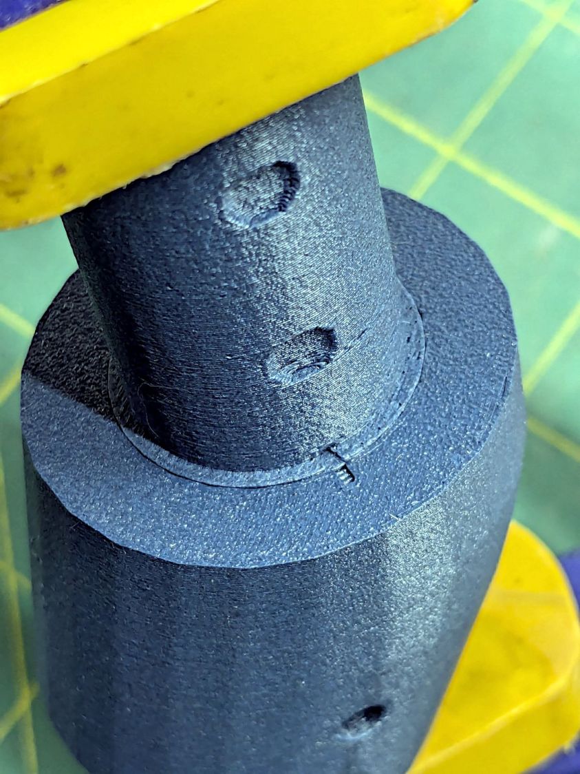
The grips slide into the bottom of the angle block where they’re captured by four M4 setscrews threaded through square nuts:

The big washer over on the right sits under the screw I used to pull the nuts into their recesses, where they sit firmly without adhesive.
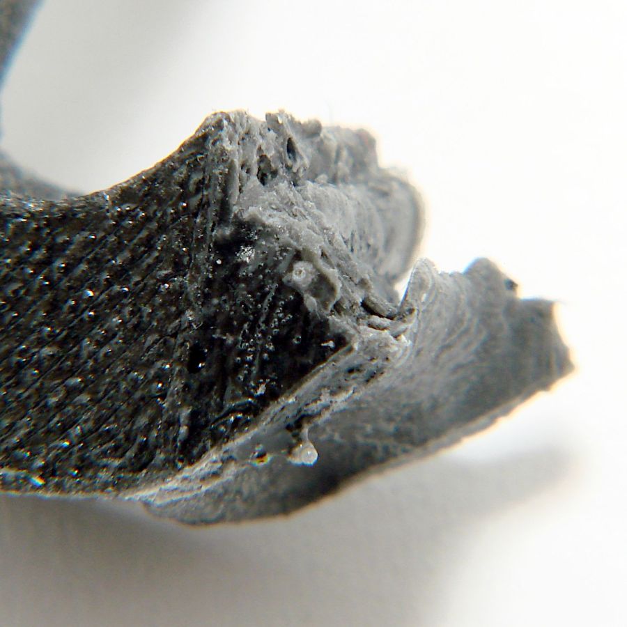
The first iterations used heat-staked brass inserts that didn’t provide enough griptivity against the torque generated by shoving the grips sideways. I probably applied more force than they’ll ever see in real life, but I’m no Hulk and I didn’t like the feel.
The upper plug gets glued into the lower angle with JB PlasticBonder urethane adhesive. Had they been finished, the first two iterations would have had screws through the angle block into brass inserts in the plug, but I realized adhesives would work much better. A pair of index marks aligns the two pieces:
It’s early days, but the machine fits her much better than it did before.
The OpenSCAD source code as a GitHub Gist:
| // Handiquilter HQ Sixteen front handlebar grip angle mount | |
| // Ed Nisley – KE4ZNU | |
| // 2024-11-29 | |
| include <BOSL2/std.scad> | |
| Layout = "Show"; // [Show,Build,Plug,Block,Covers,Cover] | |
| Material = "All"; // [All,Cover,Text] | |
| // Angle w.r.t. base | |
| GripAngle = 20; // [10:30] | |
| // Plug glued, not screwed | |
| PlugGlue = true; | |
| // Square nuts, not inserts | |
| SquareNuts = true; | |
| // Additional length of bottom | |
| AddLength = 0; // [0:20] | |
| // Separation in Show display | |
| Gap = 5; // [0:20] | |
| /* [Hidden] */ | |
| HoleWindage = 0.1; | |
| Protrusion = 0.1; | |
| NumSides = 2*3*4; | |
| ID = 0; | |
| OD = 1; | |
| LENGTH = 2; | |
| Grip = [19.7,22.4,20.0]; // (7/8)*INCH = 22.2 mm + roughness, LENGTH=OEM insertion depth | |
| GripRadius = Grip[OD]/2; // used everywhere | |
| Plug = [15.0,Grip[OD],45.0]; // inserts into handlebar base | |
| PlugRim = [Plug[ID],25.0,10.0]; // … sits against handlebar base | |
| BaseScrewPositions = [[11.0,12.0],[27.0,29.0]]; // setscrew offsets from rim top: side,rear | |
| BaseCutout = [Plug[OD]/2,Plug[ID],10]; // cable cutout into base | |
| BaseCutoutOffset = 18.0; // … centerline position w.r.t. rim | |
| WallThick = 7.0; // should at least fit insert length | |
| SupportSag = 0.4; // vertical sag over support structure | |
| MidLength = AddLength + 3.0; // total length allowing for grip tube stop | |
| TopOD = PlugRim[OD] + 2*WallThick; | |
| BotOD = Grip[OD] + 2*WallThick; | |
| BaseScrew = [4.0,4.8 + HoleWindage,1.0]; // HQ 10-32 screws, LENGTH=capture dent | |
| Insert = [5.4,6.0,6.0]; // M4 inserts in plug rim | |
| //Insert = [4.0,5.0,5.0]; // M4 inserts in plug rim | |
| Screw = [3.5,4.0,1]; // M4 screws through angle block to inserts | |
| ScrewHeadOD = 7.4 + 0.4; // M4 BHCS head + comfort | |
| SquareNut = [4.0,7.0,3.0 + 0.4]; // M4 square nut LENGTH + inset allowance | |
| NutInset = GripRadius – sqrt(pow(GripRadius,2) – pow(SquareNut[OD],2)/4); | |
| PinOD = 1.2; // plug reinforcing pins | |
| NumPins = 5; | |
| CoverThick = [3.5,9.5]; // low and high sides of grip covers | |
| CoverAngle = atan((CoverThick[1] – CoverThick[0])/Plug[OD]); | |
| LogoText = ["Sew","Fine"]; | |
| LogoFont = "Fira Sans Condensed:style=SemiBold"; | |
| LogoSize = 7.5; | |
| LogoColor = "Red"; | |
| LogoThick = 0.8; | |
| //———- | |
| // Simulator for aluminum plug replacing handlebar in base | |
| module BasePlug() { | |
| difference() { | |
| union() { | |
| tube(Plug[LENGTH],(Plug[OD] – HoleWindage)/2,Plug[ID]/2,anchor=DOWN); | |
| tube(PlugRim[LENGTH],PlugRim[OD]/2,PlugRim[ID]/2,anchor=DOWN); | |
| } | |
| up(BaseCutoutOffset + PlugRim[LENGTH]) | |
| left(Plug[OD]/4) | |
| resize(BaseCutout) | |
| yrot(90) zrot(180/8) | |
| cylinder(d=1,h=1,$fn=8,center=true); | |
| up(PlugRim[LENGTH]) | |
| right(PlugRim[OD]/2 – 1.0) | |
| cube([2.0,1.0,1.0],center=true); | |
| for (i = [0:NumPins – 1]) | |
| zrot(i*360/NumPins + 180/NumPins) | |
| down(Protrusion) | |
| right((Plug[OD] + Plug[ID])/4) | |
| zrot(180/6) | |
| cylinder(d=PinOD,h=2*PlugRim[LENGTH],$fn=6); | |
| for (k = [0:1]) // recesses in plug to capture base setscrews | |
| for (a = [0:1]) | |
| up(PlugRim[LENGTH] + BaseScrewPositions[k][a]) | |
| zrot(a*90) | |
| right(Plug[OD]/2) | |
| yrot(90) zrot(180/8) | |
| cylinder(d=BaseScrew[OD],h=2*BaseScrew[LENGTH],$fn=8,center=true); | |
| if (!PlugGlue) | |
| for (a = [0:1]) // inserts for angle block screws | |
| up(PlugRim[LENGTH]/2) | |
| zrot(a*90) | |
| yrot(90) zrot(180/8) | |
| cylinder(d=Insert[OD],h=2*PlugRim[OD],$fn=8,center=true); | |
| } | |
| } | |
| //———- | |
| // Block fitting against handlebar base with handlebar angle | |
| module AngleBlock() { | |
| difference() { | |
| hull() { | |
| up((TopOD/2)*sin(GripAngle)) | |
| xrot(GripAngle) | |
| cylinder(d=TopOD,h=PlugRim[LENGTH],$fn=NumSides); | |
| for (a = [1:2:GripAngle+1]) | |
| up((TopOD/2)*sin(a-1)) | |
| hull() { | |
| xrot(a) | |
| cylinder(d=TopOD,h=0.1,$fn=NumSides); | |
| xrot(a-1) | |
| cylinder(d=TopOD,h=0.1,$fn=NumSides); | |
| } | |
| down(Grip[LENGTH] + MidLength) | |
| cylinder(d=(Grip[OD] + 2*WallThick),h=0.1,$fn=NumSides); | |
| } | |
| up((TopOD/2)*sin(GripAngle)) | |
| xrot(GripAngle) | |
| down(SupportSag) | |
| cylinder(d=(PlugRim[OD] + HoleWindage), | |
| h=PlugRim[LENGTH] + SupportSag + Protrusion, | |
| $fn=NumSides); | |
| up((TopOD/2)*sin(GripAngle)) | |
| sphere(d=PlugRim[ID],$fn=NumSides); | |
| cylinder(d=PlugRim[ID],h=(TopOD/2)*sin(GripAngle),$fn=NumSides); | |
| down(MidLength + Protrusion) | |
| cylinder(d=(Grip[ID] – 2.0),h=(MidLength + 2*Protrusion),$fn=NumSides); | |
| down(Grip[LENGTH] + MidLength + Protrusion) | |
| cylinder(d=(Grip[OD] + HoleWindage),h=(Grip[LENGTH] + Protrusion),$fn=NumSides); | |
| up((TopOD/2)*sin(GripAngle)) | |
| xrot(GripAngle) | |
| up(PlugRim[LENGTH]) | |
| right(PlugRim[OD]/2 + 0.9) | |
| cube([2.0,1.0,1.0],center=true); | |
| if (!PlugGlue) { | |
| for (a = [0:1]) | |
| up((TopOD/2)*sin(GripAngle)) | |
| xrot(GripAngle) | |
| up(PlugRim[LENGTH]/2) | |
| zrot(a*90) | |
| yrot(90) zrot(180/8) | |
| cylinder(d=Screw[OD],h=3*PlugRim[OD],$fn=8,center=true); | |
| for (a = [0:3]) | |
| up((TopOD/2)*sin(GripAngle)) | |
| xrot(GripAngle) | |
| up(PlugRim[LENGTH]/2) | |
| zrot(a*90) | |
| right(TopOD/2 – 2.0) | |
| yrot(90) zrot(180/8) | |
| cylinder(d=ScrewHeadOD,h=TopOD,$fn=8,center=false); | |
| } | |
| if (SquareNuts) { | |
| for (a = [0:1]) | |
| for (k = [1,3]) | |
| down(k*Grip[LENGTH]/4 + MidLength) | |
| zrot(a*90) | |
| right(BotOD/2) | |
| yrot(90) zrot(180/8) | |
| cylinder(d=SquareNut[ID],h=BotOD,$fn=8,center=true); | |
| for (a = [0:1]) | |
| for (k = [1,3]) | |
| down(k*Grip[LENGTH]/4 + MidLength) | |
| zrot(a*90) | |
| right(GripRadius + SquareNut[LENGTH]/2 – NutInset/2) | |
| yrot(90) | |
| cube([SquareNut[OD],SquareNut[OD],SquareNut[LENGTH] + NutInset],center=true); | |
| } | |
| else { | |
| for (a = [0:1]) | |
| for (k = [1,3]) | |
| down(k*Grip[LENGTH]/4 + MidLength) | |
| zrot(a*90) | |
| right(BotOD/2) | |
| yrot(90) zrot(180/8) | |
| cylinder(d=Insert[OD],h=BotOD,$fn=8,center=true); | |
| } | |
| } | |
| } | |
| //———- | |
| // Chip fitting against handlebar base matching top angle | |
| // Text will be invisible until sliced | |
| module GripCover(loc=LEFT,matl="Cover") { | |
| if (matl == "Text" || matl == "All") | |
| color(LogoColor) | |
| down(matl == "All" ? 0.01 : 0.0) | |
| text3d(LogoText[loc == LEFT ? 0 : 1],LogoThick,LogoSize,LogoFont, | |
| orient=DOWN,anchor=TOP,atype="ycenter"); | |
| if (matl == "Cover" || matl == "All") | |
| difference() { | |
| intersection() { | |
| yrot(loc == RIGHT ? -CoverAngle : CoverAngle) | |
| cylinder(d=Plug[OD],h=(CoverThick[0] + CoverThick[1]),anchor=CENTER); | |
| cube(2*Plug[OD],anchor=BOTTOM); | |
| } | |
| text3d(LogoText[loc == LEFT ? 0 : 1],LogoThick,LogoSize,LogoFont, | |
| orient=DOWN,anchor=TOP,atype="ycenter"); | |
| } | |
| } | |
| //———- | |
| // Build things | |
| if (Layout == "Cover") { | |
| GripCover(LEFT,Material); | |
| } | |
| if (Layout == "Covers") { | |
| left(Plug[OD]) GripCover(LEFT,"Cover"); | |
| left(Plug[OD]) GripCover(LEFT,"Text"); | |
| right(Plug[OD]) GripCover(RIGHT,"Cover"); | |
| right(Plug[OD]) GripCover(RIGHT,"Text"); | |
| } | |
| if (Layout == "Plug") | |
| BasePlug(); | |
| if (Layout == "Block") | |
| AngleBlock(); | |
| if (Layout == "Show") { | |
| up((TopOD/2)*sin(GripAngle) + Protrusion) | |
| xrot(GripAngle) | |
| up(Plug[LENGTH] + CoverThick[1] + Gap) | |
| yrot(180 + CoverAngle) | |
| GripCover(RIGHT,"All"); | |
| up((TopOD/2)*sin(GripAngle) + Protrusion) | |
| xrot(GripAngle) | |
| up(Gap) | |
| color("Lime",0.75) | |
| BasePlug(); | |
| render() | |
| difference() { | |
| AngleBlock(); | |
| back(50) right(50) | |
| cube(100,center=true); | |
| } | |
| color("Silver",0.5) | |
| down(MidLength + Gap) | |
| tube(3*Grip[LENGTH],GripRadius,Grip[ID]/2,anchor=TOP); | |
| } | |
| if (Layout == "Build") { | |
| mirror_copy([1,0,0]) { | |
| right(BotOD) { | |
| up((TopOD/2)*sin(GripAngle) + PlugRim[LENGTH]*cos(GripAngle) + Protrusion) | |
| xrot(180 – GripAngle) | |
| AngleBlock(); | |
| back(1.5*max(TopOD,BotOD)) | |
| BasePlug(); | |
| } | |
| } | |
| fwd(60) { | |
| left(Plug[OD]) GripCover(LEFT,"Cover"); | |
| right(Plug[OD]) GripCover(RIGHT,"Cover"); | |
| } | |
| fwd(60) { | |
| left(Plug[OD]) GripCover(LEFT,"Text"); | |
| right(Plug[OD]) GripCover(RIGHT,"Text"); | |
| } | |
| } |


