Ed Nisley's Blog: Shop notes, electronics, firmware, machinery, 3D printing, laser cuttery, and curiosities. Contents: 100% human thinking, 0% AI slop.
Category: Software
General-purpose computers doing something specific
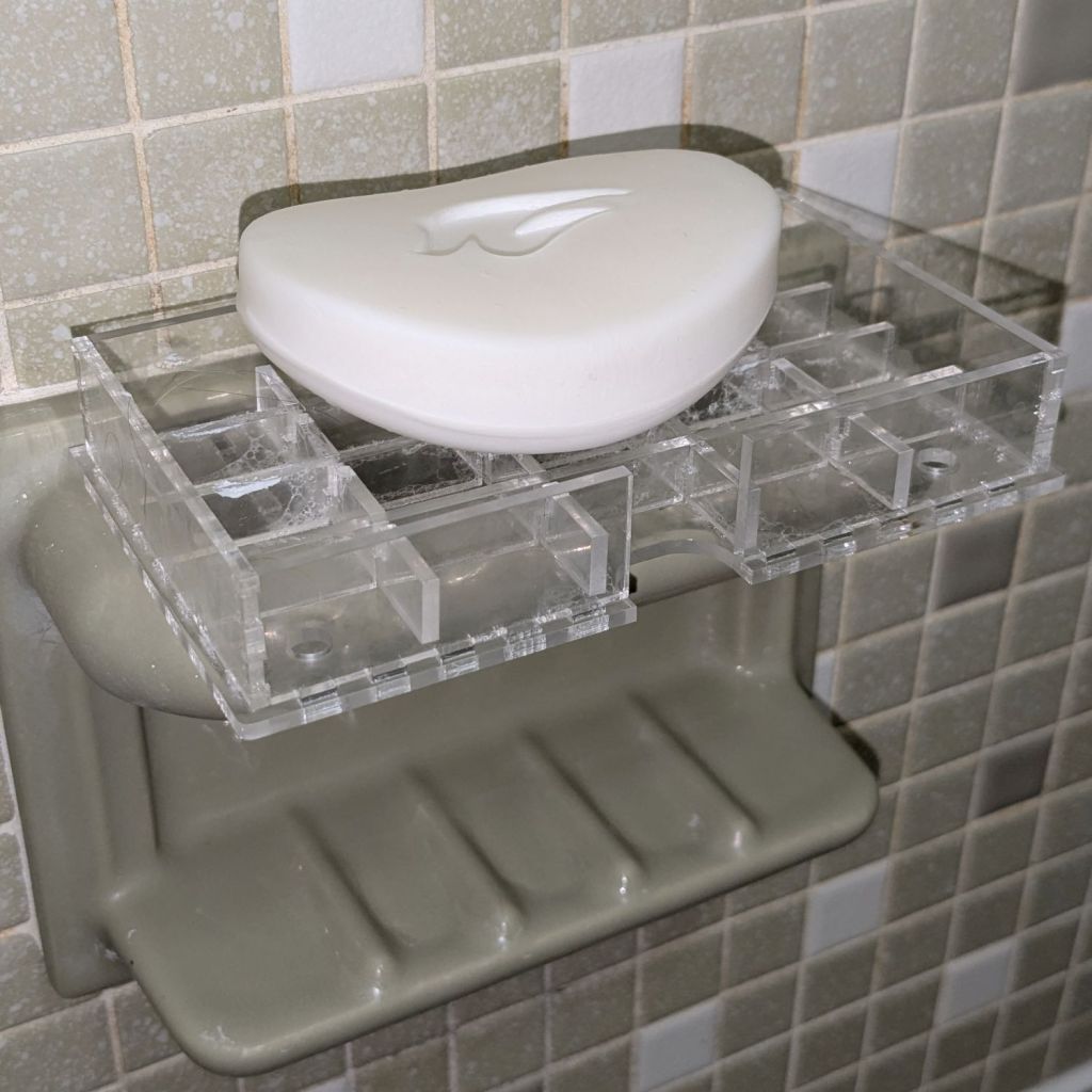
As expected, the adhesive foam strips I used on the bathtub soap tray didn’t survive continued exposure to hot soapy water, so Version 2 includes hooks securing it to the ceramic soap tray and a few other tweaks:
Bathtub Soap Tray – V2 – LightBurn layout
The view from the top:
Soap Tray V2 – top
The hooks are more visible from the bottom, as is the 10 AWG copper wire preventing the whole affair from rotating around the ceramic handle from the weight of the soap bar:
Soap Tray V2 – bottom
Ignore the usual crud you’ll find on your ceramic soap tray, too.
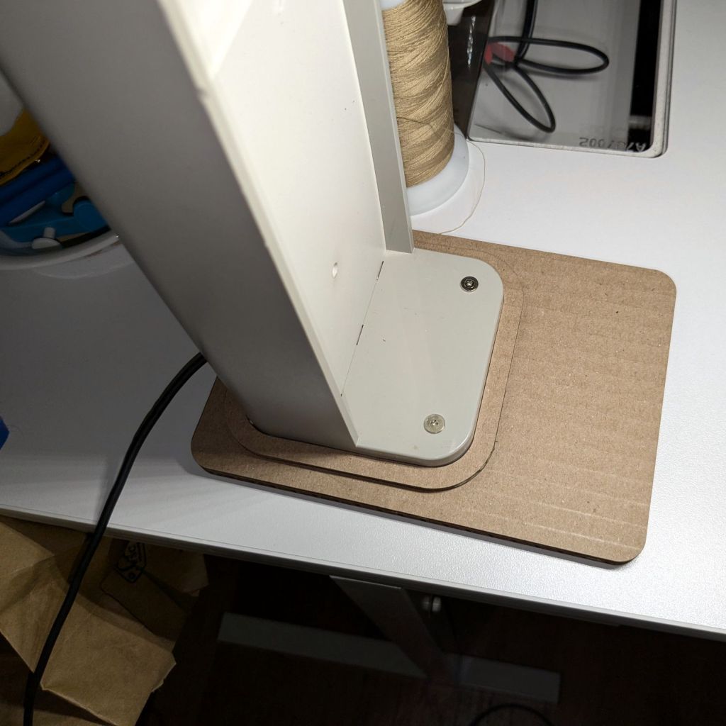
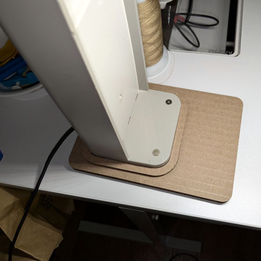
It’s not particularly elegant, what with being cardboard, but it’s a proof of concept that will determine the final size.
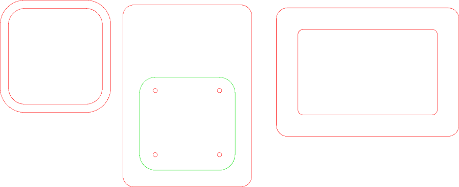
The top layer is a ring around the lamp pedestal for a bit of stabilization protecting the four M3 screws holding the base to the lamp. Those screws sit on a 60 mm square, offset 1 mm to the front of the lamp:
NisLite Baseplate – LightBurn layout
Which explains why I typically make the first few versions of anything out of cardboard.
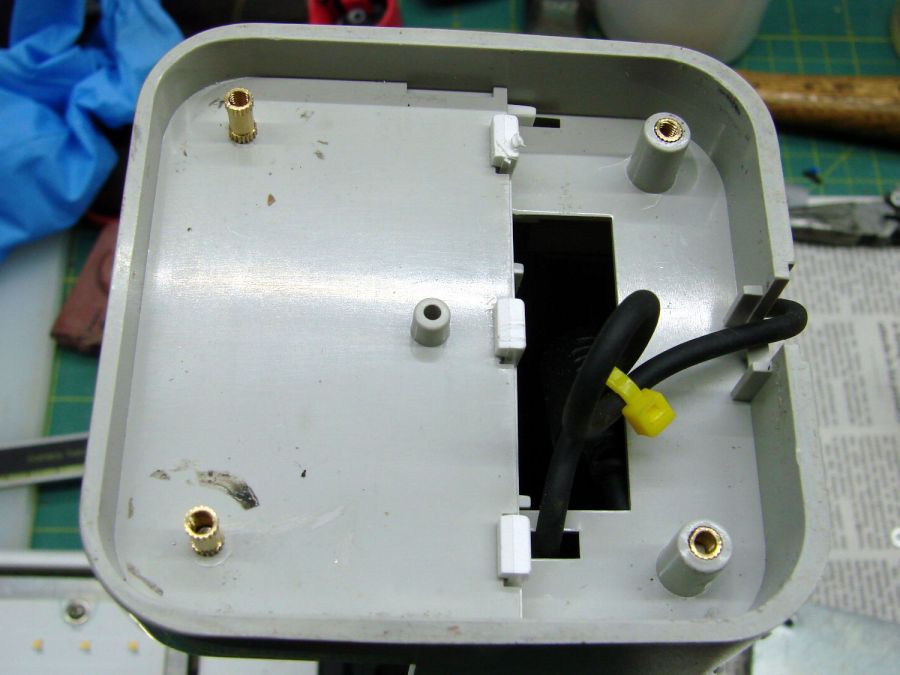
For the record, those inserts look like this:
Converted Ottlite – brass inserts
A pair of very flat-head M3 screws hold the front inserts in place through holes match-drilled in the remains of the bosses I’d long ago epoxied in place. I pressed the rear inserts in place by misusing the drill press, as the lamp is much too tall for the heat setter.
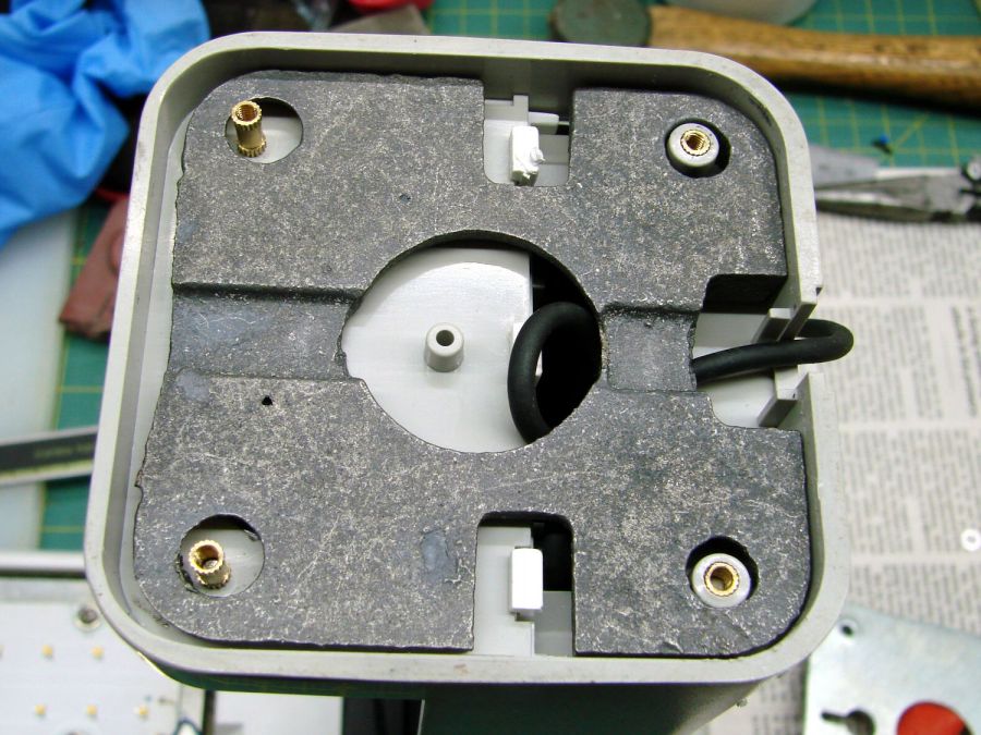
Then comes the iron base weight:
Converted Ottlite – iron weight
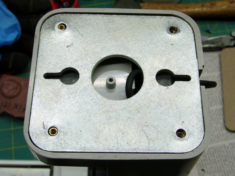
And then the steel outer plate:
Converted Ottlite – steel cover plate
The new base plate gets a ring around its perimeter for clearance under the four pan head M3 screws into the inserts.
If the cardboard base is stable enough, we’ll do an acrylic version in cheerful primary colors.
The LightBurn layout in SVG format as a GitHub Gist:
While cleaning dead bugs out of the ceiling lamps, we discovered the kitchen light was missing one of the three nuts holding its cover in place. While spare nuts might be available, this seemed like a quicker & easier solution:
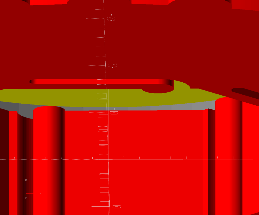
Ceiling Lamp Nut – bottom view – solid model
The stepped interior fits a brass insert with 8-32 threads (not metric, to my utter astonishment) rammed in place with a heat-set tool:
Ceiling Lamp Nut – insert staking
Using the nominal diameters seems to work fine, although I’m sure some finesse will be needed with smaller inserts.
Printed four just to be sure, rammed three inserts, and they’re ready:
Ceiling Lamp Nuts – as-built
The curved cap matches the original nut through the use of the Chord Equation to get the cap radius as a function of its height (sagitta) & base diameter. Admittedly, it looks kinda grotty with only a dozen layers, but it’s the thought that counts.
The original nuts are heavy knurled steel and the new ones are cheap plastic, but nobody will ever know:
Ceiling Lamp Nut – installed
Bonus: now I have two spare steel nuts for the next time …
A special request came in for cart coins with a handle:
Overstuffed cart key – 1.0EM
That’s in gray PETG-CF (carbon fiber) with Extrusion Multiplier = 1.0 based on the Pill Tube tests and and slightly lower temperatures based on the temperature tower. It definitely looks overstuffed and so does the Wipe Tower for that set of six coins:
Overstuffed cart key – wipe tower
The orange threads off to the right suggest something went terribly wrong with the top layer, which corresponds to the somewhat recessed cart image in the coin, but there were no other symptoms.
All six of the next set failed completely:
Failed cart key – 1.0EM
Apparently the nozzle hit the clotted gray filament in the Wipe Tower and stalled the X axis motor:
Failed cart key – wipe tower
That suggests the same thing happened to the first set during the last pass over the Wipe Tower, causing a less obvious failure.
Setting the Extrusion Multiplier = 0.65 produced a better result:
Cart key print – blue – 0.65EM
Albeit with a slightly understuffed top layer:
Cart key print – 0.65EM
But not by much:
Cart key print – black – 0.65EM
So the answer depends slightly on the PETG-CF filament color, but not by enough to justify defining three different filament types.
Cart coins are essentially solid plastic layers with no empty infill, so they have nowhere for excess filament to hide. The Wipe Tower should have plenty of room, but even at EM=0.65 the tower looks overstuffed on the side with the carbon fiber purge lines:
Cart key print 0.65EM – wipe towers
The default 110% line spacing in the tower seems too small for PETG-CF, so I’ll increase it to 150% to see if that reduces the clumping.
Judged by the surface finish, a 0.65 Extrusion Multiplier is too low, so I’ll try a set of coins at 0.80.
The test patterns will require power / speed tweakage to properly mark cardboard on other machines. The vector boxes are about 1.5 mm wide: these are small differences in small patterns.
The setup for both LightBurn 1.7 RC-13 and RDWorks 8.01.65:
The engraved patterns run at 500 mm/s & 20% power
The lines & letters run at 100 mm/s & 8% Min – 9% Max power
All on white cardboard, with image contrast blown out
Scanning offset = 0.2 mm = the usual setting for my machine
In LightBurn:
Scanning Offset 0.2 – LightBurn
In RDWorks:
Scanning Offset 0.2 – RDWorks
The slight shift to the left in the LightBurn results shows LB does not shift the uni-directional pattern to line up with the vector shape as RDWorks does, which is what started the forum thread.
Scanning offset = 1.0 mm to accentuate the difference, while shredding the bi-direction pattern as expected.
LightBurn’s uni-directional engraved pattern is still in the same slightly leftward-shifted position relative to the vectors, showing the offset value has not been applied:
Scanning Offset 1.0 – LightBurn
RDWorks definitely applies the offset in both modes:
Scanning Offset 1.0 – RDWorks
I do not know why RDWorks did not output the final “l” over there on the right, but it did so on some (not all) of the patterns while setting things up. The jank is strong with it.
So having LightBurn apply the same offset value for both uni- and bi-directional engravings would fix the (slight) offset in my machine. I think it will also fix the much larger misalignment in [the other] machine in that forum discussion.
The whole problem seems to arise from the response time of the HV power supply / laser tube: the position of the left & right edges of the scanned output line depend critically on the rising and falling edges of the current applied to the tube and its power output.
Being me, of course, makes me want a different offset value applied to the uni-directional case, just for fine tuning. Which would require a duplicate offset-per-speed table and that looks like a UX disaster comin’ on strong.
The last time around, I used Cart Coins to verify platform alignment (a.k.a. “leveling”) on the Makergear M2. The Prusa MK4 does mesh probing to ensure accurate alignment, so these new Cart Coins exercised the MMU3 and gave me some giveaways for a recent dinner:
TroCraft Eco is within 0.1 mm of the proper thickness
Laser-cut coins proceed with great speed
Normally you’d export the finished layout as an SVG, but OpenSCAD ignores “holes” within shapes, so I exported it as a PNG to serve as a binary height map:
Import the PNG into OpenSCAD using surface()
Resize it to 20 mm wide and 1.7 mm tall
Knock it out of a 24 mm OD × 1.6 mm tall cylinder (which is why the extra 0.1 mm)
Add the PNG again as a separate 1.6 mm object to refill the hole
Whereupon out pops a solid model:
Cart Coin – solid model
Export that as a 3mf file to keep the two objects aligned, import it into PrusaSlicer, then get multi-material on it:
Cart Coin – PrusaSlicer layout
There’s a fourth group with different colors in hiding. I printed 12 identical coins at a time, mostly so I could keep track of what was happening, and it ended well enough.
The black coins with the translucent retina-burn orange cart look surprisingly good.
But this is way faster:
They’re the size of a US quarter, because that’s what unlocks shopping carts around here. Feel free to tweak the parameters for your locale.
The kitchen counter has only two useful places for the cutting board and the spot Mary favors puts a distinct swale under one corner. A bit of measuring and solid modeling produced a simple shim to make the answer come out right:
Cutting Board shim – solid model
The basic shape is union() of a trio of hull() operations forming the three sides, with the text label as a separate object to verify I understood how to build a multi-material object.
Export it as a 3mf file, open it in PrusaSlicer, slice, print:
Cutting Board shim – label
Putting the label on the bottom surface takes advantage of the nubbly finish on the Textured Steel Sheet to make it look like it just grew in there.
The label is just barely visible from the top, despite extending only 1/4 of the way through the 1.6 mm bottom slab:
Cutting Board shim – top
So white PETG needs more than 1.2 mm of thickness to hid a black feature. Today I Learned, etc.
Multi-material printing produces a Wipe Tower to hold all the extruded junk during color changes:
Cutting Board shim – wipe tower
The curl under the nozzle comes from the final ramming used to shape the end of the filament into a point for reliable material / color changing.
Although a shim is something of a nuisance, it works perfectly:
Cutting Board shim – in use
Much easier than installing an L-shaped Corian slab with a sink cutout!
The faded engraving dates back to the early days of the laser …
This file contains hidden or bidirectional Unicode text that may be interpreted or compiled differently than what appears below. To review, open the file in an editor that reveals hidden Unicode characters.
Learn more about bidirectional Unicode characters