The Smell of Molten Projects in the Morning

Ed Nisley's Blog: Shop notes, electronics, firmware, machinery, 3D printing, laser cuttery, and curiosities. Contents: 100% human thinking, 0% AI slop.

Category: Software

General-purpose computers doing something specific

  • Renaming Files With Sequential Numbers, Plus Moviemaking Therefrom

    The avconv (formerly ffmpeg) image-to-video programs expect sequentially numbered files, with the numbers in a fixed-width part of the file name, thusly: dsc00001.jpg.

    Given a set of files (previously normalized to lowercase) like this:

    ll | head
    total 286576
    -rwxr-xr-x 1 ed ed 595708 Jan 23 19:14 dsc00940.jpg
    -rwxr-xr-x 1 ed ed 515561 Jan 23 19:14 dsc00941.jpg
    -rwxr-xr-x 1 ed ed 580190 Jan 23 19:14 dsc00942.jpg
    -rwxr-xr-x 1 ed ed 571387 Jan 23 19:14 dsc00943.jpg
    -rwxr-xr-x 1 ed ed 573207 Jan 23 19:14 dsc00944.jpg
    -rwxr-xr-x 1 ed ed 571086 Jan 23 19:14 dsc00945.jpg
    -rwxr-xr-x 1 ed ed 571600 Jan 23 19:14 dsc00946.jpg
    -rwxr-xr-x 1 ed ed 571547 Jan 23 19:14 dsc00947.jpg
    -rwxr-xr-x 1 ed ed 565706 Jan 23 19:15 dsc00948.jpg
    

    A Bash one-liner loop does the renumbering:

    sn=1 ; for f in *jpg ; do printf -v dn 'dsc%05d.jpg' "$(( sn++ ))" ; mv $f $dn ; done
    

    The results look pretty much like you’d expect:

    ll | head
    total 286556
    -rwxr-xr-x 1 ed ed 595708 Jan 23 19:14 dsc00001.jpg
    -rwxr-xr-x 1 ed ed 515561 Jan 23 19:14 dsc00002.jpg
    -rwxr-xr-x 1 ed ed 580190 Jan 23 19:14 dsc00003.jpg
    -rwxr-xr-x 1 ed ed 571387 Jan 23 19:14 dsc00004.jpg
    -rwxr-xr-x 1 ed ed 573207 Jan 23 19:14 dsc00005.jpg
    -rwxr-xr-x 1 ed ed 571086 Jan 23 19:14 dsc00006.jpg
    -rwxr-xr-x 1 ed ed 571600 Jan 23 19:14 dsc00007.jpg
    -rwxr-xr-x 1 ed ed 571547 Jan 23 19:14 dsc00008.jpg
    -rwxr-xr-x 1 ed ed 565706 Jan 23 19:15 dsc00009.jpg
    

    Because you’re renaming the files anyway, don’t bother to normalize ’em:

    sn=1 ; for f in *JPG ; do printf -v dn 'dsc%05d.jpg' "$(( sn++ ))" ; mv $f $dn ; done
    

    And, of course, you can fetch ’em from the camera while doing that:

    sn=1 ; for f in /mnt/part/DCIM/100MSDCF/*JPG ; do printf -v dn 'dsc%05d.jpg' "$(( sn++ ))" ; cp -a $f $dn ; done
    

    That leaves the DSC*JPG original files on the camera, where you can delete all of them in one operation when you’re happy with the results.

    If you don’t need the full resolution, reserialize and resize each picture on the fly:

    sn=1 ; for f in /mnt/part/DCIM/100MSDCF/*JPG ; do printf -v dn 'dsc%05d.jpg' "$(( sn++ ))" ; convert $f -resize 50% $dn ; done
    

    That’s based on combining several hints turned up by the usual Google search.

    To assemble a quick-and-simple movie from the images:

    avconv -r 30 -i dsc%05d.jpg -q 5 movie.mp4
    

    The image quality certainly isn’t up to what you (well, I) would expect from a 1920×1080 “HD” file, but the Sony HDR-AS30V Zeiss camera lens seems to be a fisheye pinhole (170° view angle, 2.5 mm f/2.8) backed with relentless image compression:

    Sony HDR-AS30V Action Camera
    Sony HDR-AS30V Action Camera

    Memo to Self: It’s not worth creating and remembering Yet Another Script.

  • Changing the Case of a FAT File Name

    While converting a stop-action series of images from the HDR-AS30V into a movie, I wanted change all the image files on a USB Flash drive from DSC00008.JPG to dsc00008.jpg, so as to simplify typing their names.

    Alas, because the camera’s exFAT filesystem cares not one whit about case, the obvious command doesn’t work:

    rename 's/JPG/jpg/' /mnt/part/*
    /mnt/part/DSC00008.JPG not renamed: /mnt/part/DSC00008.jpg already exists
    

    So you must do each piece in two steps:

    rename 's/JPG/jpgx/' /mnt/part/*
    rename 's/jpgx/jpg/' /mnt/part/*
    rename 's/DSC/dscx/' /mnt/part/*
    rename 's/dscx/dsc/' /mnt/part/*
    

    Obvious once you see it, I suppose…

    See the comments for a better way:

    rename 'y/A-Z/a-z/' *JPG
    
  • Sony NP-BX1 Battery Test Fixture

    The Sony HDR-AS30V “action camera” uses NP-BX1 lithium batteries (3.7 V @ 1.24 A·h = 4.6 W·h) that are, of course, a completely different size and shape than any other lithium battery on the planet.

    So.

    Tweaking a few dimensions in the Canon NB-6L source code, tinkering with the layout of the contact pins, and shazam Yet Another 3D Printed Battery Test Fixture:

    NP-BX1 Holder - show layout
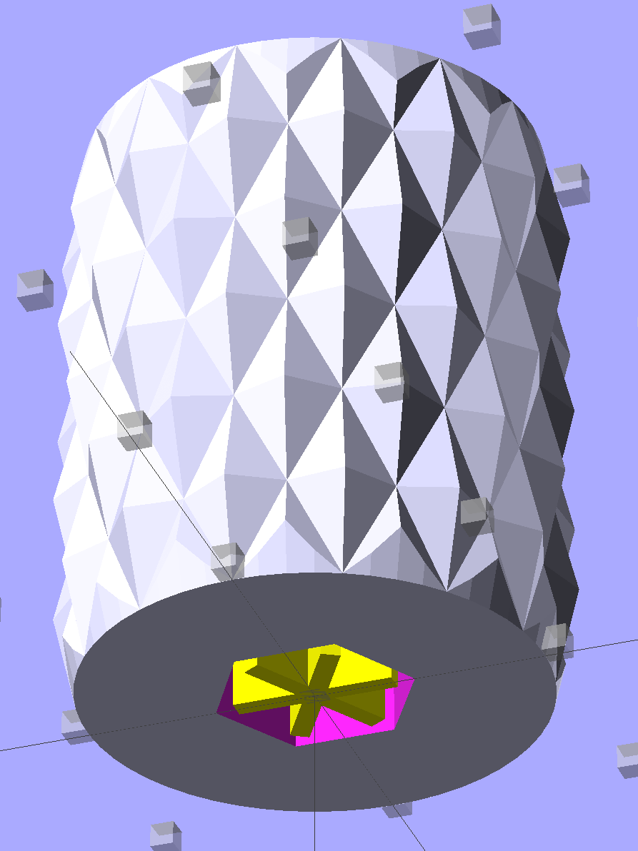
    NP-BX1 Holder – show layout

    It builds nicely, although the contact pin tunnels are a bit too close to the top of the case:

    Sony NP-BX1 Holder - on platform
    Sony NP-BX1 Holder – on platform

    After reaming out the contact pin holes to the proper diameters & depths, then gluing the plugs in place, it works just as you’d expect:

    Sony NP-BX1 battery holder
    Sony NP-BX1 battery holder

    It’s worth noting that the Wasabi charger accepts the batteries upside-down, with the conspicuous chevron against the charger body. It’s definitely not the way all the other chargers work. The keying recesses on the battery (corresponding to the blocks in the solid model) lie along the bottom edge of the contact surface, so flipping the battery over means they’ll hold it in place, but … oh, well.

    That grotty Powerpole connector last saw use in some random benchtop lashup. At some point I’ll be forced to start making more of those.

    The OpenSCAD source code:

    // Holder for Sony NP-BX1 Li-Ion battery
    // Ed Nisley KE4ZNU January 2013
    
    include <MCAD/boxes.scad>
    
    // Layout options
    
    Layout = "Show";					//  Show Build Fit Case Lid Pins Plugs AlignPins
    
    //- Extrusion parameters - must match reality!
    //  Print with +2 shells and 3 solid layers
    
    ThreadThick = 0.20;
    ThreadWidth = 0.40;
    
    HoleWindage = 0.2;
    
    function IntegerMultiple(Size,Unit) = Unit * ceil(Size / Unit);
    
    Protrusion = 0.1;			// make holes end cleanly
    
    inch = 25.4;
    
    BuildOffset = 3.0;			// clearance for build layout
    
    Gap = 8.0;					// separation for Fit parts
    
    //- Battery dimensions - rationalized from several samples
    //  Coordinate origin at battery corner by contact plates on bottom surface
    
    BatteryLength = 43.0;
    BatteryWidth = 30.0;
    BatteryThick =  9.5;
    
    ContactWidth = 2.90;
    ContactLength = 4.30;
    ContactRecess = 0.90;
    
    ContactOC = 10.0;			// center-to-center across contact face
    ContactOffset = 6.20;		// offset from battery edge
    ContactHeight = 6.30;		// offset from battery bottom plane
    
    AlignThick = 2.75;			// alignment recesses on contact face
    AlignDepth = 1.70;			// into face
    AlignWidth1 = 3.70;			// across face at contacts
    AlignWidth2 = 3.60;			//  ... other edge
    
    //- Pin dimensions
    
    PinTipDia = 1.6;
    PinTipLength = 10.0;
    
    PinTaperLength = 2.3;
    
    PinShaftDia = 2.4;
    PinShaftLength = 6.8;
    
    PinFerruleDia = 3.1;
    PinFerruleLength = 2.0;
    
    PinLength = PinTipLength + PinTaperLength + PinShaftLength + PinFerruleLength;
    
    ExtendRelax = 1.5 + ContactRecess;		// pin extension when no battery is present
    ExtendOvertravel = 1.0;					//  ... beyond engaged position
    
    //- Spring dimensions
    
    SpringDia = 3.1;						// coil OD
    SpringMax = 9.3;
    SpringLength = SpringMax - 0.5;			// slightly compressed
    SpringMin = 4.5;
    
    SpringPlugOD = IntegerMultiple(5.0,ThreadWidth);		// plug retaining the spring
    SpringPlugID = 2.0;
    SpringPlugLength = IntegerMultiple(4.0,ThreadWidth);
    SpringPlugSides = 3*4;
    
    SpringTravel = ExtendRelax + ExtendOvertravel;
    
    //- Holder dimensions
    
    GuideRadius = ThreadWidth;			// friction fit ridges
    GuideOffset = 7;					// from compartment corners
    WallThick = 4*ThreadWidth;			// holder sidewalls
    
    BaseThick = 6*ThreadThick;			// bottom of holder to bottom of battery
    TopThick = 6*ThreadThick;			// top of battery to top of holder
    
    ThumbRadius = 10.0;			// thumb opening at end of battery
    
    CornerRadius = 3*ThreadThick;			// nice corner rounding
    
    CaseLength = SpringPlugLength + SpringLength + PinLength - ExtendRelax
    			+ BatteryLength + GuideRadius + WallThick;
    CaseWidth = 2*WallThick + 2*GuideRadius + BatteryWidth;
    CaseThick = BaseThick + BatteryThick + TopThick;
    
    AlignPinOD = 1.75;			// lid alignment pins - filament snippets
    AlignPinLength = 5.0;
    AlignPinInset = 7.0;
    AlignPinOffset = -3.75;		//  from centerline - choose to miss contact pins
    
    //- XY origin at front left battery corner, Z on platform below that
    
    CaseLengthOffset = -(SpringPlugLength + SpringLength + PinLength - ExtendRelax);
    CaseWidthOffset = -(WallThick + GuideRadius);
    CaseThickOffset = BaseThick;
    
    LidLength = ExtendRelax - CaseLengthOffset;
    
    echo(str("Contact pin tip dia: ",PinTipDia));
    echo(str("Drill depth to taper end: ",
    		 (SpringPlugLength + SpringLength + PinFerruleLength + PinShaftLength + PinTaperLength),
    		 " -- Dia: ",PinShaftDia));
    echo(str("            to ferrule end: ",
    		  (SpringPlugLength + SpringLength + PinFerruleLength),
    		 " -- Dia: ",PinFerruleDia));
    echo(str("            to plug end: ",SpringPlugLength,
    		 " -- Dia: ",SpringPlugOD));
    
    //----------------------
    // Useful routines
    
    module PolyCyl(Dia,Height,ForceSides=0) {			// based on nophead's polyholes
    
      Sides = (ForceSides != 0) ? ForceSides : (ceil(Dia) + 2);
    
      FixDia = Dia / cos(180/Sides);
    
      cylinder(r=(FixDia + HoleWindage)/2,
               h=Height,
    	   $fn=Sides);
    }
    
    module ShowPegGrid(Space = 10.0,Size = 1.0) {
    
      Range = floor(50 / Space);
    
    	for (x=[-Range:Range])
    	  for (y=[-Range:Range])
    		translate([x*Space,y*Space,Size/2])
    		  %cube(Size,center=true);
    
    }
    
    //-------------------
    
    //-- Guides for tighter friction fit
    
    module Guides() {
      	  translate([GuideOffset,-GuideRadius,CaseThickOffset])
    		PolyCyl(2*GuideRadius,(BatteryThick - Protrusion),4);
    	  translate([GuideOffset,(BatteryWidth + GuideRadius),CaseThickOffset])
    		PolyCyl(2*GuideRadius,(BatteryThick - Protrusion),4);
    	  translate([(BatteryLength - GuideOffset),-GuideRadius,CaseThickOffset])
    		PolyCyl(2*GuideRadius,(BatteryThick - Protrusion),4);
    	  translate([(BatteryLength - GuideOffset),(BatteryWidth + GuideRadius),CaseThickOffset])
    		PolyCyl(2*GuideRadius,(BatteryThick - Protrusion),4);
    	  translate([(BatteryLength + GuideRadius),GuideOffset/2,CaseThickOffset])
    		PolyCyl(2*GuideRadius,(BatteryThick - Protrusion),4);
    	  translate([(BatteryLength + GuideRadius),(BatteryWidth - GuideOffset/2),CaseThickOffset])
    		PolyCyl(2*GuideRadius,(BatteryThick - Protrusion),4);
    
    }
    
    //-- Contact pins (holes therefore)
    
    module PinShape() {
    
      union() {
    	cylinder(r=(PinTipDia + HoleWindage)/2,h=(PinTipLength + Protrusion),$fn=6);
    
    	translate([0,0,PinTipLength])
    	  cylinder(r=(PinShaftDia + HoleWindage)/2,
    			   h=(PinTaperLength + PinShaftLength + Protrusion),$fn=6);
    
    	translate([0,0,(PinLength - PinFerruleLength)])
    	  cylinder(r=(PinFerruleDia + HoleWindage)/2,
    				h=(PinFerruleLength + Protrusion),$fn=6);
    
    	translate([0,0,(PinLength)])
    	  cylinder(r=(SpringDia + HoleWindage)/2,
    				h=(SpringLength + Protrusion),$fn=6);
    
    	translate([0,0,(PinLength + SpringLength - HoleWindage)])	// windage for hole length
    	  cylinder(r=(SpringPlugOD + HoleWindage)/2,h=3*SpringPlugLength,$fn=SpringPlugSides);
    
    //	  translate([0,0,(PinLength + SpringLength + SpringPlugLength)])
    //	  cylinder(r=(SpringPlugOD + HoleWindage)/2,h=2*SpringPlugLength,$fn=SpringPlugSides);	// extend hole
      }
    
    }
    
    module PinAssembly() {
    
      translate([ExtendRelax,ContactOffset,CaseThickOffset + ContactHeight]) {
    	rotate([0,270,0]) {
    	  PinShape();												// pins
    	  translate([0,(1*ContactOC),0])
    		PinShape();
    	}
      }
    
    }
    
    //-- Alignment pins
    
    module AlignPins() {
    
    	for (x=[-1,1])
    		translate([x*(LidLength - 2*AlignPinInset)/2,AlignPinOffset,0])
    			rotate(45)
    			PolyCyl(AlignPinOD,AlignPinLength);
    }
    
    //-- Case with origin at battery corner
    
    module Case() {
    
      difference() {
    
    	union() {
    
    	  difference() {
    		translate([(CaseLength/2 + CaseLengthOffset),
    				  (CaseWidth/2 + CaseWidthOffset),
    				  (CaseThick/2)])
    		  roundedBox([CaseLength,CaseWidth,CaseThick],CornerRadius); 	// basic case shape
    
    		translate([-ExtendOvertravel,-GuideRadius,CaseThickOffset])
    		  cube([(BatteryLength + GuideRadius + ExtendOvertravel),
    				(BatteryWidth + 2* GuideRadius),
    				(BatteryThick + Protrusion)]);						// battery space
    
    	  }
    
    	  Guides();
    
    	  translate([-ExtendOvertravel,-GuideRadius,BaseThick])
    		cube([(AlignDepth + ExtendOvertravel),
    			  (AlignWidth1 + GuideRadius),
    			  AlignThick]);											// alignment blocks
    	  translate([-ExtendOvertravel,
    				 (BatteryWidth - AlignWidth2),
    				 BaseThick])
    		cube([(AlignDepth + ExtendOvertravel),
    			  (AlignWidth2 + GuideRadius),
    			  AlignThick]);
    
    	}
    
    	translate([(-ExtendOvertravel),
    			   (CaseWidthOffset - Protrusion),
    			   (CaseThickOffset + BatteryThick)])
    	  cube([CaseLength,
    		    (CaseWidth + 2*Protrusion),
    		    (TopThick + Protrusion)]);								// battery access
    
    	translate([(CaseLengthOffset - Protrusion),
    			   (CaseWidthOffset - Protrusion),
    			   (CaseThickOffset + BatteryThick)])
    	  cube([(CaseLength + 2*Protrusion),
    		    (CaseWidth + 2*Protrusion),
    		    (TopThick + Protrusion)]);								// battery insertion allowance
    
    	translate([(BatteryLength - Protrusion),
    			    (CaseWidth/2 + CaseWidthOffset),
    			    (CaseThickOffset + ThumbRadius)])
    	  rotate([90,0,0])
    		rotate([0,90,0])
    		  cylinder(r=ThumbRadius,
    				   h=(WallThick + GuideRadius + 2*Protrusion),
    				   $fn=22);											// remove thumb notch
    
    	PinAssembly();
    
    	translate([-LidLength/2,BatteryWidth/2,CaseThick - TopThick - (AlignPinLength - TopThick/2)])
    		AlignPins();
      }
    
    }
    
    module Lid() {
    
      difference() {
    	translate([0,0,(CaseThick/2 - BaseThick - BatteryThick)])
    	  roundedBox([LidLength,
    				 CaseWidth,CaseThick],CornerRadius);
    
    	translate([0,0,-(CaseThick/2)])
    	  cube([(LidLength + 2*Protrusion),
    		    (CaseWidth + 2*Protrusion),
    		    (CaseThick)],center=true);
    
    	translate([-ExtendRelax,0,-(AlignPinLength - TopThick/2)])
    		AlignPins();
      }
    
    }
    
    module PlugShape() {
    
      difference() {
    	cylinder(r=SpringPlugOD/2,h=SpringPlugLength,$fn=SpringPlugSides);
    	translate([0,0,-Protrusion])
    	  PolyCyl(SpringPlugID,(SpringPlugLength + 2*Protrusion),SpringPlugSides);
      }
    }
    
    module Plugs() {
      translate([0,ContactOC,0])
    	PlugShape();
      translate([0,-ContactOC,0])
    	PlugShape();
    }
    
    //-------------------
    // Build it!
    
    ShowPegGrid();
    
    if (Layout == "Case")
      Case();
    
    if (Layout == "Lid")
      Lid();
    
    if (Layout == "Plugs")
    	for (i=[-1:1])
    		translate([i*1.5*SpringPlugOD,0,0])
    			Plugs();
    
    if (Layout == "Pins")
      PinShape();
    
    if (Layout == "AlignPins")
      AlignPins();
    
    if (Layout == "Show") {								// reveal pin assembly
      difference() {
    	Case();
    
    	translate([(CaseLengthOffset - Protrusion),
    			   (CaseWidthOffset - Protrusion + WallThick + ContactOffset + ContactOC),
    			   (BaseThick + ContactHeight)])
    	  cube([(-CaseLengthOffset + Protrusion),
    			 (CaseWidth + 2*Protrusion),
    			 CaseThick + BaseThick - ContactHeight + Protrusion]);
    
    	translate([(CaseLengthOffset - Protrusion),
    			   (CaseWidthOffset - Protrusion),
    			   -Protrusion])
    	  cube([(-CaseLengthOffset + Protrusion),
    			 (WallThick + GuideRadius + ContactOffset + Protrusion),
    			 CaseThick]);
      }
    
      translate([ExtendRelax,ContactOffset,(CaseThickOffset + ContactHeight)]) {	// pins
    	rotate([0,270,0]) {
    	  %PinShape();
    //	  translate([0,(2*ContactOC),0])
    //		%PinShape();
    	}
      }
    
      translate([CaseLengthOffset,ContactOffset,(CaseThickOffset + ContactHeight)])
    	rotate([0,90,0])
    	  PlugShape();
    }
    
    if (Layout == "Build") {
      translate([-(CaseLength/2 + CaseLengthOffset),-(CaseWidthOffset - BuildOffset),0])
    	Case();
      translate([CaseWidth/2,(CaseLengthOffset/2 - BuildOffset),0])
    	rotate([0,0,90])
    	  Lid();
      for (i=[-1:1])
    	translate([CaseLengthOffset/2 + i*1.5*SpringPlugOD,-CaseWidth/2,0])
    		Plugs();
    }
    
    if (Layout == "Fit") {
      Case();
      translate([(-LidLength/2 + ExtendRelax),
    			(CaseWidth/2 + CaseWidthOffset),
    			(BaseThick + BatteryThick + Gap)])
    	  Lid();
      translate([ExtendRelax,ContactOffset,CaseThickOffset + ContactHeight]) {	// pins
    	rotate([0,270,0]) {
    	  %PinShape();
    	  translate([0,(1*ContactOC),0])
    		%PinShape();
    	}
      }
    
      translate([CaseLengthOffset,
    			(ContactOffset + ContactOC),
    			(CaseThickOffset + ContactHeight)])
      rotate([0,90,0])
    	Plugs();
    
      translate([-LidLength/2,BatteryWidth/2,CaseThick])
    #	AlignPins();
    
    }
    
  • Modified Quilting Foot: Speed Wrench Knob

    The Nyloc nut atop that modified quilting foot requires more grip than fingers can provide:

    Modified Darning Foot - in action
    Modified Darning Foot – in action

    The “precision” wrench I adapted to that nut works for small adjustments, but for larger ones it’s easier to take the foot off and spin this knob:

    Quilting Foot Knob - knurling
    Quilting Foot Knob – knurling

    It has a hex opening in each end that fits the nut, with a through hole for the bolt. The top looks exactly like you’d expect:

    Quilting Foot Knob - top
    Quilting Foot Knob – top

    The bottom needs a bit of support:

    Quilting Foot Knob - bottom support
    Quilting Foot Knob – bottom support

    The solid model shows off the support in color:

    Quilting Foot Knob
    Quilting Foot Knob

    The OpenSCAD source code doesn’t have many surprises:

    // Quilting foot knob
    // Ed Nisley KE4ZNU January 2013
    
    use <knurledFinishLib_v2.scad>
    
    //- Extrusion parameters must match reality!
    //  Print with +1 shells and 3 solid layers
    
    ThreadThick = 0.20;
    ThreadWidth = 0.40;
    
    HoleWindage = 0.2;
    
    function IntegerMultiple(Size,Unit) = Unit * ceil(Size / Unit);
    
    Protrusion = 0.1;			// make holes end cleanly
    
    //----------------------
    // Dimensions
    
    KnobOD = 20.0;
    KnobLength = 25.0;
    KnobSides = 12;
    
    DiamondLength = KnobLength/3;
    DiamondWidth = DiamondLength/2;
    DiamondDepth = 1.0;
    
    NutOD = 7.0;				// across flats!
    NutLength = 6.0;
    ScrewOD = 4.0;
    
    DoSupport = true;
    
    //----------------------
    // Useful routines
    
    module PolyCyl(Dia,Height,ForceSides=0) {			// based on nophead's polyholes
    
      Sides = (ForceSides != 0) ? ForceSides : (ceil(Dia) + 2);
    
      FixDia = Dia / cos(180/Sides);
    
      cylinder(r=(FixDia + HoleWindage)/2,
               h=Height,
    	   $fn=Sides);
    }
    
    module ShowPegGrid(Space = 10.0,Size = 1.0) {
    
      RangeX = floor(100 / Space);
      RangeY = floor(125 / Space);
    
    	for (x=[-RangeX:RangeX])
    	  for (y=[-RangeY:RangeY])
    		translate([x*Space,y*Space,Size/2])
    		  %cube(Size,center=true);
    
    }
    
    module Knob() {
    	rotate(180/Sides) {
    		difference() {
    //			cylinder(r=KnobOD/2,h=KnobLength,$fn=KnobSides);
    			render(convexity=10)
    			knurl(k_cyl_hg=KnobLength,
    				  k_cyl_od=KnobOD,
    				  knurl_wd=DiamondWidth,
    				  knurl_hg=DiamondLength,
    				  knurl_dp=DiamondDepth,
    				  e_smooth=DiamondLength/2);
    			translate([0,0,-Protrusion])
    				PolyCyl(ScrewOD,(KnobLength + 2*Protrusion),6);
    			translate([0,0,(KnobLength - NutLength)])
    				PolyCyl(NutOD,(NutLength + Protrusion),6);
    			translate([0,0,-Protrusion])
    				PolyCyl(NutOD,(NutLength + Protrusion),6);
    		}
    	}
    }
    
    module Support() {
    	color("Yellow")
    		for (Seg=[0:5]) {
    			rotate(360*Seg/6)
    			translate([0,0,(NutLength - ThreadThick)/2])
    				cube([(NutOD - 1*ThreadWidth),
    						2*ThreadWidth,
    						(NutLength - ThreadThick)],
    						center=true);
    			}
    }
    
    //----------------------
    // Build them!
    
    ShowPegGrid();
    
    Knob();
    
    if (DoSupport)
    	Support();
    

    Mary likes it… and thinks I’m being silly. She’s right, of course.

  • Forcing Pulseaudio DisplayPort Volume Initialization

    It turns out that the audio-over-HDMI/DisplayPort channel which, for whatever reason, is the only way to get audio out of the Optiplex 980 with the big Dell U2711 monitor starts up AT MAXIMUM VOLUME! regardless of the GUI’s Pulseaudio mixer setting that’s diligently saved-and-restored across sessions. That makes a certain perverse sense, as the digital-to-analog converter & power amp live inside the monitor.

    Manually adjusting the GUI mixer by one click, either up or down, forces the new setting out over the digital link to the monitor, after which the audio output corresponds to the mixer; I never remember that until just after some dipshit auto-play video lights up with a fanfare.

    Setting the mixer to the same value doesn’t force an update, so the obvious solution (at least to me) of sending a fixed initial value doesn’t work; it’s optimized away. I think that’s why the initial update doesn’t happen: the stored volume is the same as the, ah, stored volume, so there’s no need to tell the monitor.

    The automatic solution involves putting two more commands in my ever-growing ~/.config/startup.sh:

    amixer -D pulse sset Master 26%
    amixer -D pulse sset Master 1%-
    

    That sets a rational level (which might be the same as the existing one from the previous session), then changing it by one tiny click to force the new value out to the monitor.

    And then It Just Works…

  • Rounded Rectangles in OpenSCAD: Mold Positives?

    A discussion on the OpenSCAD mailing list about making a rectangular solid with rounded edges having different radii eventually produced this delightful result:

    Basic Rounded Cube
    Basic Rounded Cube

    Those guys make me feel dumb, because they’re generally solving problems I can’t even imagine, but I know what to do with this solution. One could slice it in half horizontally, emboss a height map defining a logo / picture into the top surface, print it out on your favorite 3D printer, maybe smooth / seal the surface a bit, define it to be a positive mold pattern, cast / pour flexible silicone around it, and get a negative mold for a pourable precious material such as, oh, chocolate.

    You could make half a dozen of them, arrange them inside a suitable printed frame, pour the silicone, and get a multi-cavity mold for better manufacturing productivity.

    The overall block lacks draft, because the problem it solves presumes you need a block of specific outside dimensions: it overlays three full-size rectangular blocks that define the dimensions. OpenSCAD constructs spheres such that they may be slightly smaller than the defined radius at the poles and, depending on their alignment, a face at the equator may reduce the outer dimension of a surrounding hull.

    Given a sufficiently bendy silicone mold, you might not need any draft at all. If you do need draft and you don’t care about a very slightly undersized pattern, remove the internal blocks and increase the XY spacing of the lower four spheres by enough to make the draft come out right.

    The grayscale logo / image should have nice smooth transitions that produce suitable draft for the fine details; a bare black-and-white image might not work well. Shallow is good, but that conflicts with 3D printing’s crappy resolution: 1 mm = 10 layers, tops. That might not matter in practice.

    You’re supposed to temper the chocolate, but that’s probably more relevant for Fine Art molds.

    The (slightly modified) OpenSCAD source code:

    module rcube(size=[30, 20, 10], radius=[3, 2, 1], center=true)
    	hull() {
    		translate( center ? [0,0,0] : size/2 ) {
    			cube(size-2*radius+[2*radius[0],0,0],center=true);
    			cube(size-2*radius+[0,2*radius[1],0],center=true);
    			cube(size-2*radius+[0,0,2*radius[2]],center=true);
    
    			for(x = [-0.5,0.5], y = [-0.5,0.5], z = [-0.5,0.5])
    				translate([x * ( size[0] - 2*radius[0]),
    						   y * ( size[1] - 2*radius[1]),
    						   z * ( size[2] - 2*radius[2])])
    					scale([radius[0], radius[1], radius[2]])
    						sphere(1.0,$fn=4*4);
    		}
    	}
    
    rcube();
    

    When I get around to doing molds, maybe I can remember what I was thinking…

  • Thing-O-Matic 286 Conversion: Slic3r Configuration

    The Thing-O-Matic hardware isn’t up to the standards of, say, an M2, but, after all my tweakage, it’s Good Enough for most purposes. These Slic3r settings should provide a reasonable starting point to get it working the way it used to with its new controller.

    The key extrusion dimensions:

    • 0.4 mm nozzle → 0.5 mm minimum thread width
    • 0.25 mm layer thickness

    The speeds come from the old Skeinforge configuration, dialed back a bit for sanity:

    • 150 mm/s non-printing XY travel
    • 10 mm/s minimum printing speed
    • 20 mm/s first layer printing for better adhesion
    • 40 mm/s general printing
    • 60 mm/s infill

    Some of the finer settings are completely arbitrary and everything requires tweaking, along with Marlin’s acceleration & jerk settings, for best picture.

    The exported Slic3r configuration:

    # generated by Slic3r 1.0.0RC1 on Fri Jan 17 11:25:02 2014
    avoid_crossing_perimeters = 0
    bed_size = 105,120
    bed_temperature = 110
    bottom_solid_layers = 3
    bridge_acceleration = 0
    bridge_fan_speed = 100
    bridge_flow_ratio = 1
    bridge_speed = 40
    brim_width = 0
    complete_objects = 0
    cooling = 1
    default_acceleration = 0
    disable_fan_first_layers = 1000
    duplicate = 1
    duplicate_distance = 6
    duplicate_grid = 1,1
    end_gcode = ;---- end.gcode starts ----\n; TOM 286 - Al plates + Geared extruder\n; Ed Nisley - KE4ZNU - January 2014\n; Marlin with tweaks for Azteeg X3 with thermocouple\n;- inhale filament blob\nG91\nG1 E-5 F900\nG90\n;- turn off heaters\nM104 S0         ; extruder head\nM140 S0         ; HBP\n;- move to eject position\nG1 Z999 F1000   ; home Z to get nozzle away from object\nG92 Z115      ; reset Z\nG1 X0 F6000     ; center X axis\nG1 Y35          ; move Y stage forward\n;---- end.gcode ends ----
    external_perimeter_speed = 50%
    external_perimeters_first = 0
    extra_perimeters = 1
    extruder_clearance_height = 20
    extruder_clearance_radius = 20
    extruder_offset = 0x0
    extrusion_axis = E
    extrusion_multiplier = 1.00
    extrusion_width = 0.50
    fan_always_on = 0
    fan_below_layer_time = 1
    filament_diameter = 2.95
    fill_angle = 45
    fill_density = 0.15
    fill_pattern = honeycomb
    first_layer_acceleration = 0
    first_layer_bed_temperature = 110
    first_layer_extrusion_width = 0.50
    first_layer_height = 0.25
    first_layer_speed = 20
    first_layer_temperature = 200
    g0 = 0
    gap_fill_speed = 30
    gcode_arcs = 0
    gcode_comments = 0
    gcode_flavor = reprap
    infill_acceleration = 0
    infill_every_layers = 3
    infill_extruder = 1
    infill_extrusion_width = 0.50
    infill_first = 1
    infill_only_where_needed = 1
    infill_speed = 60
    layer_gcode =
    layer_height = 0.25
    max_fan_speed = 100
    min_fan_speed = 35
    min_print_speed = 10
    min_skirt_length = 5
    notes =
    nozzle_diameter = 0.4
    only_retract_when_crossing_perimeters = 1
    ooze_prevention = 0
    output_filename_format = [input_filename_base].gcode
    overhangs = 1
    perimeter_acceleration = 0
    perimeter_extruder = 1
    perimeter_extrusion_width = 0.50
    perimeter_speed = 40
    perimeters = 2
    post_process =
    print_center = 0,0
    raft_layers = 0
    randomize_start = 1
    resolution = 0.05
    retract_before_travel = 0.5
    retract_layer_change = 0
    retract_length = 2
    retract_length_toolchange = 10
    retract_lift = 0
    retract_restart_extra = 0
    retract_restart_extra_toolchange = 0
    retract_speed = 60
    rotate = 0
    scale = 1
    skirt_distance = 2
    skirt_height = 1
    skirts = 3
    slowdown_below_layer_time = 15
    small_perimeter_speed = 50%
    solid_fill_pattern = rectilinear
    solid_infill_below_area = 5
    solid_infill_every_layers = 0
    solid_infill_extrusion_width = 0.50
    solid_infill_speed = 150%
    spiral_vase = 0
    standby_temperature_delta = -5
    start_gcode = ;---- start.gcode begins ----\n; TOM 286 - Al plates + Geared extruder + Zmin platform sense\n; Ed Nisley - KE4ZNU - January 2014\n; Marlin with tweaks for Azteeg X3 with thermocouple\n;\n; Set initial conditions\nG21                 ; set units to mm\nG90                 ; set positioning to absolute\n;----------\n; Begin heating\nM104 S[first_layer_temperature]         ; extruder head\nM140 S[first_layer_bed_temperature]    ; start bed heating\n;----------\n; Home axes\nG28 X0 Y0 Z0\nG92 X-53.5 Y-58.5 Z115.0\n;----------\n; Initial nozzle wipe to clear snot for Z touchoff\nG1 X0 Y0 Z3.0 F1500     ; pause at center to build confidence\nG4 P1000\nG1 Z10                  ; ensure clearance\nG1 X39 Y-58.0 F10000    ; move to front, avoid wiper blade\nG1 X55                  ; to wipe station\nG1 Z6.0                 ; to wipe level\nM116                    ; wait for temperature settling\nG1 Y-45 F500            ; slowly wipe nozzle\n;-----------------------------------------------\n; Z platform height touchoff\n; Make sure the XY position is actually over the switch!\n; Home Z downward to platform switch\n; Compensate for 0.05 mm backlash in G92: make it 0.05 too low\nG1 X56.0 Y8.2 Z4.0 F6000     ; get over build platform switch\n;G1 Z0 F50                    ; home downward very slowly\n;G92 Z1.45                    ; set Z-min switch height\nG1 Z6.0 F1000                ; back off switch to wipe level\n;-----------------------------------------------\n; Prime extruder to stabilize initial pressure\nG1 X55 Y-45 F6000   ; set up for wipe from rear\nG1 Y-58.0 F500      ; wipe to front\nG91                 ; use incremental motion for extrusion\nG1 F2               ; set slow rate\nG1 E10              ; extrude enough to get good pressure\nG1 F4000            ; set for fast retract\nG1 E-2.0            ; retract\nG90                 ; back to absolute motion\nG1 Y-45 F1000       ; wipe nozzle to rear\n;----------\n; Set up for Skirt start in left rear corner\n; Compensate for Z backlash: move upward from zero point\nG1 X-50 Y55 Z0.0 F10000     ; left rear corner -- kiss platform\nG1 Z0.2 F1500       ; take up Z backlash to less than thread height\nG92 E1.0            ; preset to avoid huge un-Reversal blob\n;G1 X0 Y0\n;---- start.gcode ends ----
    start_perimeters_at_concave_points = 1
    start_perimeters_at_non_overhang = 1
    support_material = 0
    support_material_angle = 0
    support_material_enforce_layers = 0
    support_material_extruder = 1
    support_material_extrusion_width = 0.50
    support_material_interface_extruder = 1
    support_material_interface_layers = 3
    support_material_interface_spacing = 0
    support_material_pattern = honeycomb
    support_material_spacing = 2.5
    support_material_speed = 60
    support_material_threshold = 0
    temperature = 200
    thin_walls = 1
    threads = 2
    toolchange_gcode =
    top_infill_extrusion_width = 0.50
    top_solid_infill_speed = 50%
    top_solid_layers = 3
    travel_speed = 150
    use_firmware_retraction = 0
    use_relative_e_distances = 0
    vibration_limit = 0
    wipe = 0
    z_offset = 0