Ed Nisley's Blog: Shop notes, electronics, firmware, machinery, 3D printing, laser cuttery, and curiosities. Contents: 100% human thinking, 0% AI slop.
Category: Software
General-purpose computers doing something specific
Mary’s Sears Kenmore Model 158 sewing machine arm has a flat rear surface and a plastic plate on the front, so double-sided adhesive foam tape can hold a straight mount in place; we rejected putting strips under the arm to avoid snagging on the quilts as they pass by. So, with LEDs in hand, these are the mounts…
LED strip lights must have strain relief for their wires, as our Larval Engineer discovered the hard way on her longboard ground lighting project, and I wanted nice endcaps to avoid snagging on the fabric, so the general idea was a quarter-round rod with smooth endcaps and a hole to secure the wire. Some experiments showed that the acrylic (?) LED encapsulation directed the light downward, thus eliminating the need for a shade.
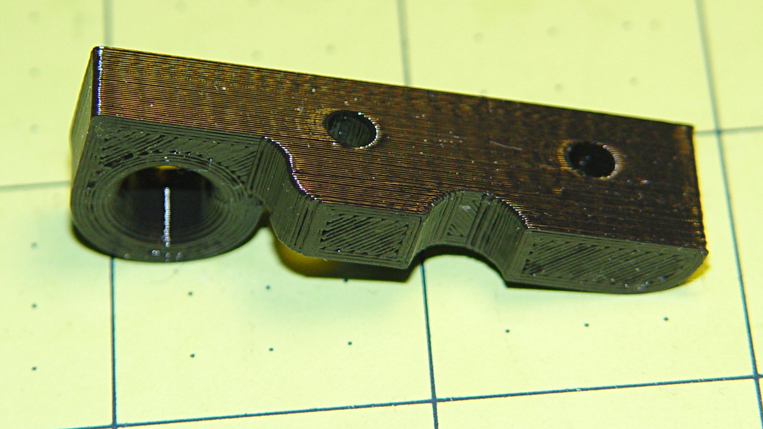
So, something like this will do for a first pass:
LED Strip Light Mount – bottom view
The overall dimensions for the LED mounts:
Length: N x 25 mm, plus endcap radii
Front-to-back width: 10 mm to allow for strip variation and 1 mm protection
Top-to-bottom height: 12 mm to fit double-sided foam sticky squares
Wire channels: 3 mm diameter or square cross-section
If there’s not enough light, I think a double-wide mount with two parallel LED strips would work.
After a bit of screwing around with additive endcaps that produced catastrophically non-manifold solid models, I figured out the proper subtractive way to build the mounts: the endcaps actually define the overall shape of the mount.
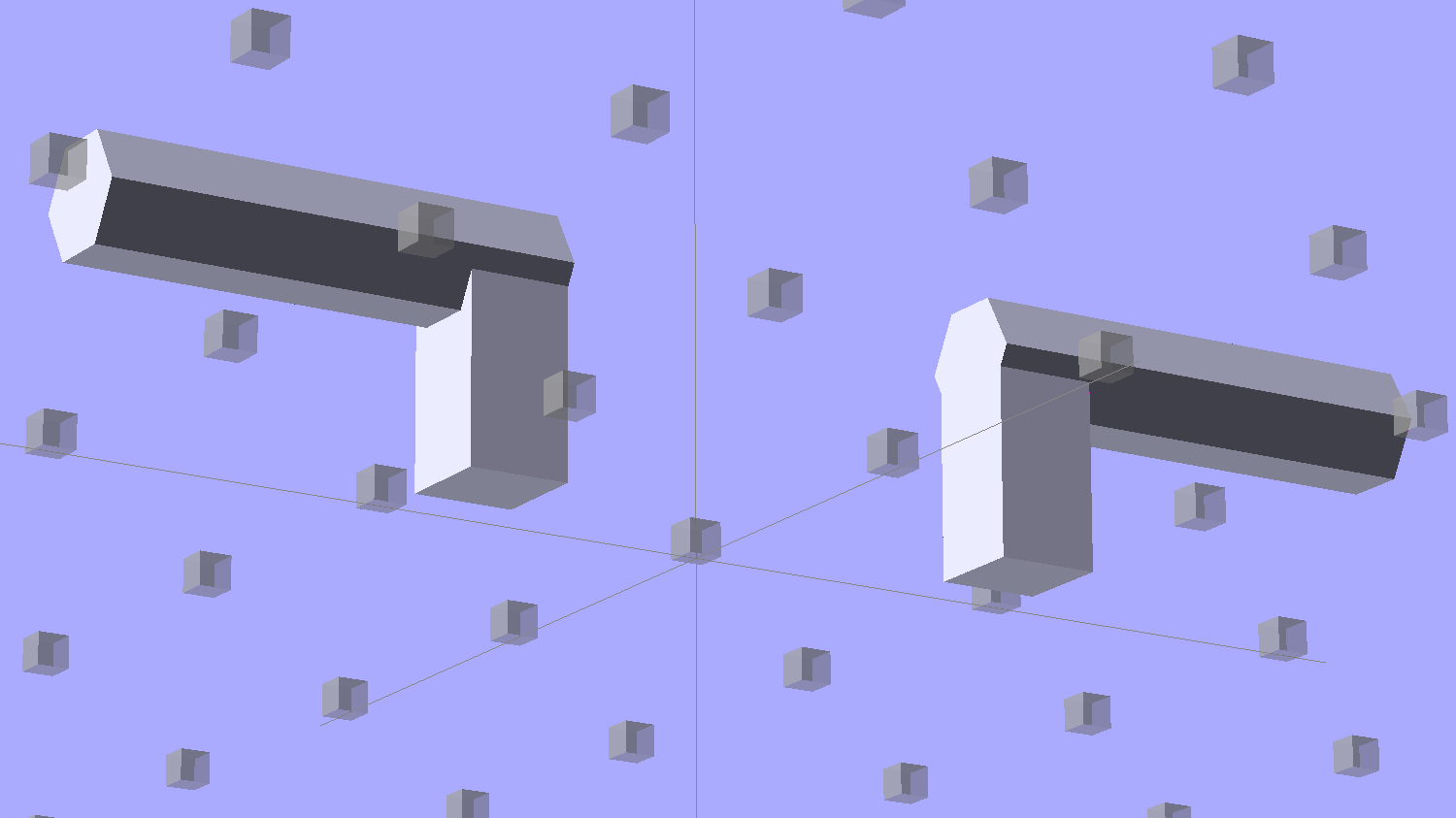
Start by placing a pair of spheroids, with radii matching the strip dimensions, so that their outer poles match the desired overall length:
Strip Light Mount – end cap spheroids – whole
The north/south poles must face outward, so that the equal-angle facets along the equators match up with what will become the mount body: rotate the spheroids 90° around the Y axis. The centers lie at the ends of the LED segments; the model shown here has a single 25 mm segment.
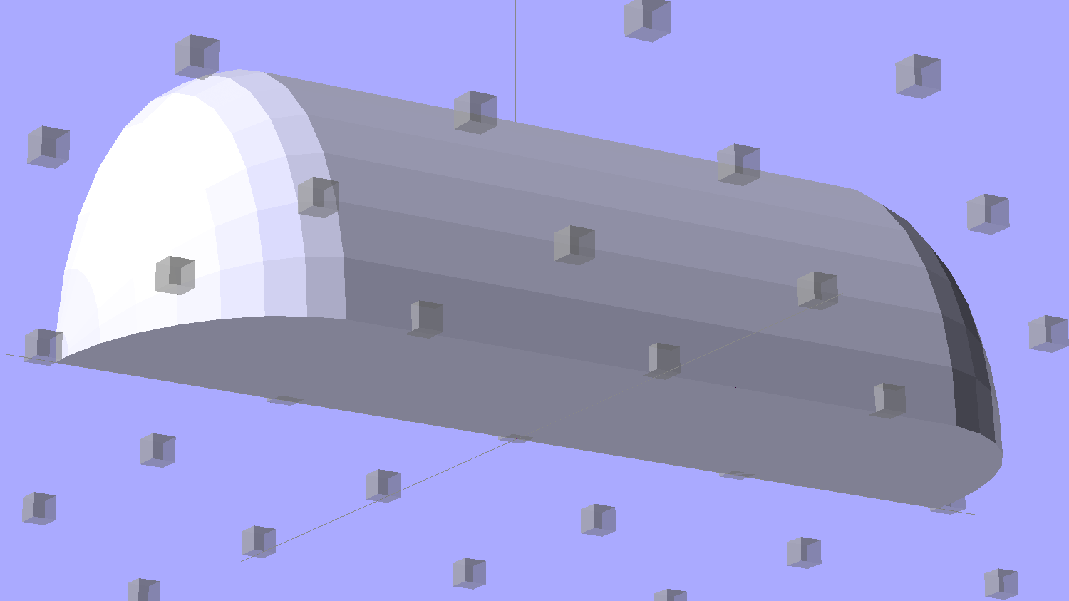
Then hack off three quadrants:
Strip Light Mount – end cap spheroids
That leaves two orange-segment shapes that define the endcaps:
Strip Light Mount – end caps – shaped
Here’s the key step that took me far too long to figure out. Shrinkwrapping the endcaps with the hull() function finesses the problem of matching the body facets to the endcap facets:
Strip Light Mount – end caps – hull
Model the wire channels as positive volumes that will be subtracted from the mount. The Channels layout shows both channels separated by a short distance:
Strip Light Mount – positive wire channels
The horizontal hexagons started as squares, but that looked hideous on the rounded endcaps.
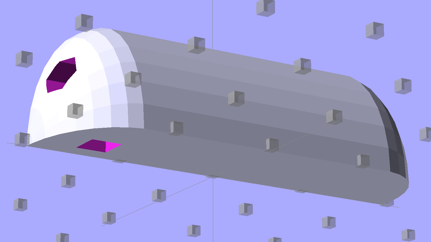
Seen from the bottom, the mount starts like this:
Strip Light Mount – no wiring channels
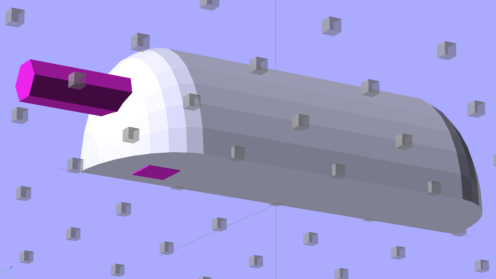
Position and subtract a wire channel:
Strip Light Mount – visible wire channel
Which leaves the final solid model as a single, manifold object:
Strip Light Mount – complete
The module generating the mount takes three parameters: the number of LED segments and two string variables that determine whether to punch a channel in each endcap. Instantiate the module three times with suitable parameters to get a trio of LED mounts, all laid out for 3D printing:
Strip Light Mount – build layout
They built just exactly like those models would suggest; the M2 produces dependable results.
The OpenSCAD source code:
// LED Strip Lighting Brackets for Kenmore Model 158 Sewing Machine
// Ed Nisley - KE4ZNU - February 2014

Layout = "Strip";			// Build Show Channels Strip

//- Extrusion parameters must match reality!
//  Print with 2 shells and 3 solid layers

ThreadThick = 0.20;
ThreadWidth = 0.40;

HoleWindage = 0.2;			// extra clearance

Protrusion = 0.1;			// make holes end cleanly

AlignPinOD = 1.70;			// assembly alignment pins: filament dia

inch = 25.4;

function IntegerMultiple(Size,Unit) = Unit * ceil(Size / Unit);

//----------------------
// Dimensions

Segment = [25.0,10.0,3.0];		//  size of each LED segment

WireChannel = 3.0;				// wire routing channel

StripHeight = 12.0;				// sticky tape width
StripSides = 8*4;

DefaultLayout = [1,"Wire","NoWire"];

EndCap = [(2*WireChannel + 1.0),Segment[1],StripHeight];	// radii of end cap spheroid
EndCapSides = StripSides;

CapSpace = 2.0;						// build spacing for endcaps
BuildSpace = 1.5*Segment[1];		// spacing between objects on platform

//----------------------
// Useful routines

module PolyCyl(Dia,Height,ForceSides=0) {			// based on nophead's polyholes

  Sides = (ForceSides != 0) ? ForceSides : (ceil(Dia) + 2);

  FixDia = Dia / cos(180/Sides);

  cylinder(r=(FixDia + HoleWindage)/2,
           h=Height,
           $fn=Sides);
}

module ShowPegGrid(Space = 10.0,Size = 1.0) {

  RangeX = floor(100 / Space);
  RangeY = floor(125 / Space);

	for (x=[-RangeX:RangeX])
	  for (y=[-RangeY:RangeY])
		translate([x*Space,y*Space,Size/2])
		  %cube(Size,center=true);

}

//-- The negative space used to thread wires into the endcap

module MakeWireChannel(Which = "Left") {

	HalfSpace = EndCap[0] * ((Which == "Left") ? 1 : -1);

	render(convexity=2)
	translate([0,EndCap[1]/3,0])
		intersection() {
			union() {
				cube([2*WireChannel,WireChannel,EndCap[2]],center=true);
				translate([-2*EndCap[0],0,EndCap[2]/2])
					rotate([0,90,0]) rotate(180/6)
						PolyCyl(WireChannel,4*EndCap[0],6);
			}
			translate([HalfSpace,0,(EndCap[2] - Protrusion)]) {
				cube(2*EndCap,center=true);
			}
		}
}

//-- The whole strip, minus wiring channels

module MakeStrip(Layout = DefaultLayout) {

	BarLength = Layout[0] * Segment[0];				// central bar length

	hull()
		difference() {
			for (x = [-1,1])						// endcaps as spheroids
				translate([x*BarLength/2,0,0])
					resize(2*EndCap) rotate([0,90,0]) sphere(1.0,$fn=EndCapSides);
			translate([0,0,-EndCap[2]])
				cube([2*BarLength,3*EndCap[1],2*EndCap[2]],center=true);
			translate([0,-EndCap[1],0])
				cube([2*BarLength,2*EndCap[1],3*EndCap[2]],center=true);
		}

}

//-- Cut wiring channels out of strip

module MakeMount(Layout = DefaultLayout) {

	BarLength = Layout[0] * Segment[0];

	difference() {
		MakeStrip(Layout);
		if (Layout[1] == "Wire")
			translate([BarLength/2,0,0])
				MakeWireChannel("Left");
		if (Layout[2] == "Wire")
			translate([-BarLength/2,0,0])
				MakeWireChannel("Right");
	}
}

//- Build it

ShowPegGrid();

if (Layout == "Channels") {
	translate([ EndCap[0],0,0]) MakeWireChannel("Left");
	translate([-EndCap[0],0,0]) MakeWireChannel("Right");
}

if (Layout == "Strip") {
	MakeStrip(DefaultLayout);
}

if (Layout == "Show") {
	MakeMount(DefaultLayout);
}

if (Layout == "Build") {

	translate([0,BuildSpace,0]) MakeMount([1,"Wire","Wire"]);		// rear left side, vertical
	translate([0,0,0]) MakeMount([5,"Wire","NoWire"]);				// rear top, across arm
	translate([0,-BuildSpace,0]) MakeMount([6,"NoWire","Wire"]);	// front top, across arm
}
The original design doodles, which bear a vague resemblance to the final mounts:
LED Strip Light Mounts – Original Design Sketches
The little snood coming out of the top would hide a wire going through a hole drilled in the capital-S of “Sears” on the front panel, but I came to my senses long before implementing that idea…
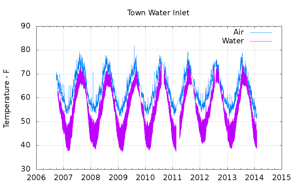
Back in 2006, I clamped a Hobo temperature sensor onto the pipe that delivers town water from the main, under 150 feet of front yard, and into our basement:
Town Water Inlet – temperature sensor mounting
Wrapping a chunk of closed-cell foam insulation around it made me feel better, but probably doesn’t affect the results very much at all:
Town Water Inlet – temperature sensor insulation
I assume the temperature of the pipe at that location will match the water temperature pretty closely, at least while some water flows into the house, and the water temperature will match the ground temperature four feet under the front yard.
Under those assumptions, the bottom trace shows the pipe temperature and the top trace shows the air temperature on the shelf a few feet above the pipe:
Town Water Inlet
The gap in early 2011 documents an embarrassing bit of forgetfulness. All in all, you’re looking at about 750,000 logged records; if you observe something long enough, it turns into science.
Cleaning up the date and time columns in the data files required a few hours of heads-down sed experimentation:
Convert quoted headers to comments → s/^\"/#&/
Convert non-data records to comments → s/^.*Logged/#&/
Convert two-digit years to four-digit years and enforce trailing blank → s_/\([01][0-9]\)[ ,]_/20\1 _
Enforce blank after four-digit years → s_/\(20[0-9]\{2\}\),_/\1 _
Remove blank after time-of-day value → s_\(:[0-9]\{2\}\) _\1_
Being reminded that sed will accept (nearly) any delimiter character came in handy!
The temperature spikes happen when I bring the Hobo datalogger upstairs to read it out. The plotting routine discards the junk readings caused by unplugging the remote sensor; anything below 30 °F or above 100 °F counts as spurious. The gnuplot idiom uses the ternary operator with the Not-a-Number value:
plot "filename" using 2:((\$3 > 30) && (\$3 < 100) ? \$3 : NaN) with ...</code>
The backslashes escape gnuplot’s variable markers, which would otherwise get eaten by Bash.
The Bash / gnuplot script that produces the plot:
#!/bin/sh
#-- overhead
export GDFONTPATH="/usr/share/fonts/truetype/"
base="${1%.*}"
echo Base name: ${base}
tfile1=$(tempfile)
ofile=${base}.png
echo Input file: $1
echo Temporary files: ${tfile1}
echo Output file: ${ofile}
#-- prepare csv Hobo logger file
sed 's/^\"/#&/ ; s/^.*Logged/#&/ ; s_/\([01][0-9]\)[ ,]_/20\1 _ ; s_/\(20[0-9]\{2\}\),_/\1 _ ; s_\(:[0-9]\{2\}\) _\1_' "$1" > ${tfile1}
#-- do it
gnuplot << EOF
set term png font "arialbd.ttf" 18 size 950,600
set output "${ofile}"
set title "${base}"
set key noautotitles
unset mouse
set grid xtics ytics
set timefmt "%m/%d/%Y %H:%M:%S"
set xdata time
#set xlabel "Week of Year"
set format x "%Y"
set ylabel "Temperature - F"
set yrange [30:90]
set datafile separator ","
plot	\
    "${tfile1}" using 2:((\$3 > 30) && (\$3 < 100) ? \$3 : NaN) with lines lt 3 title "Air", \
    "${tfile1}" using 2:((\$5 > 30) && (\$5 < 100) ? \$5 : NaN) with lines lt 4 title "Water"
EOF
Come to find out that Makerbot changed the spacing between the Y-axis rod and the idler bolt, so it doesn’t fit the TOM286. I could fire up the Token Windows Box, install Sketchup, modify the model, rebuild and clean up the STL, and try again, but it’s easier to just give up. The TOM286 has worked fine so far, so maybe this isn’t really needed.
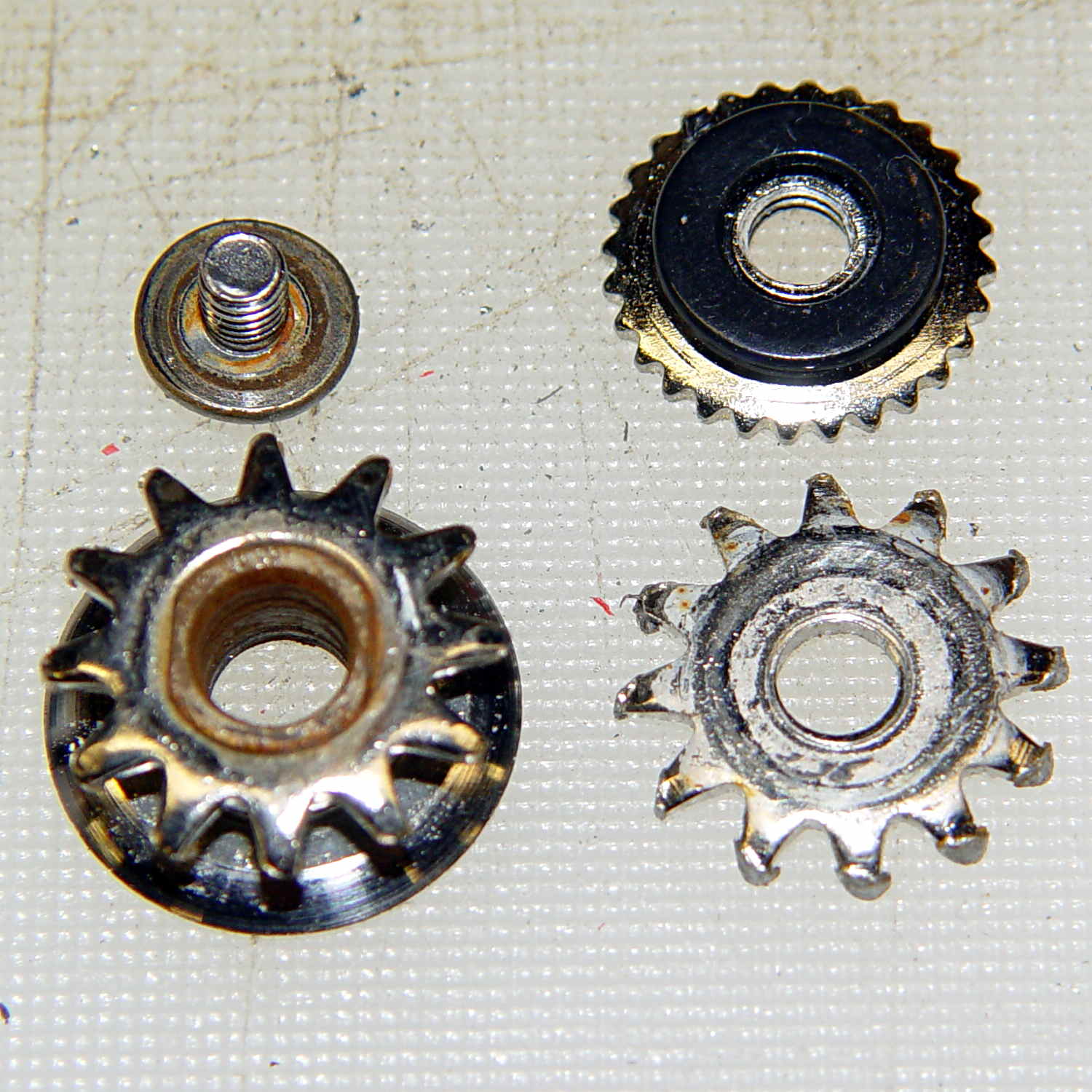
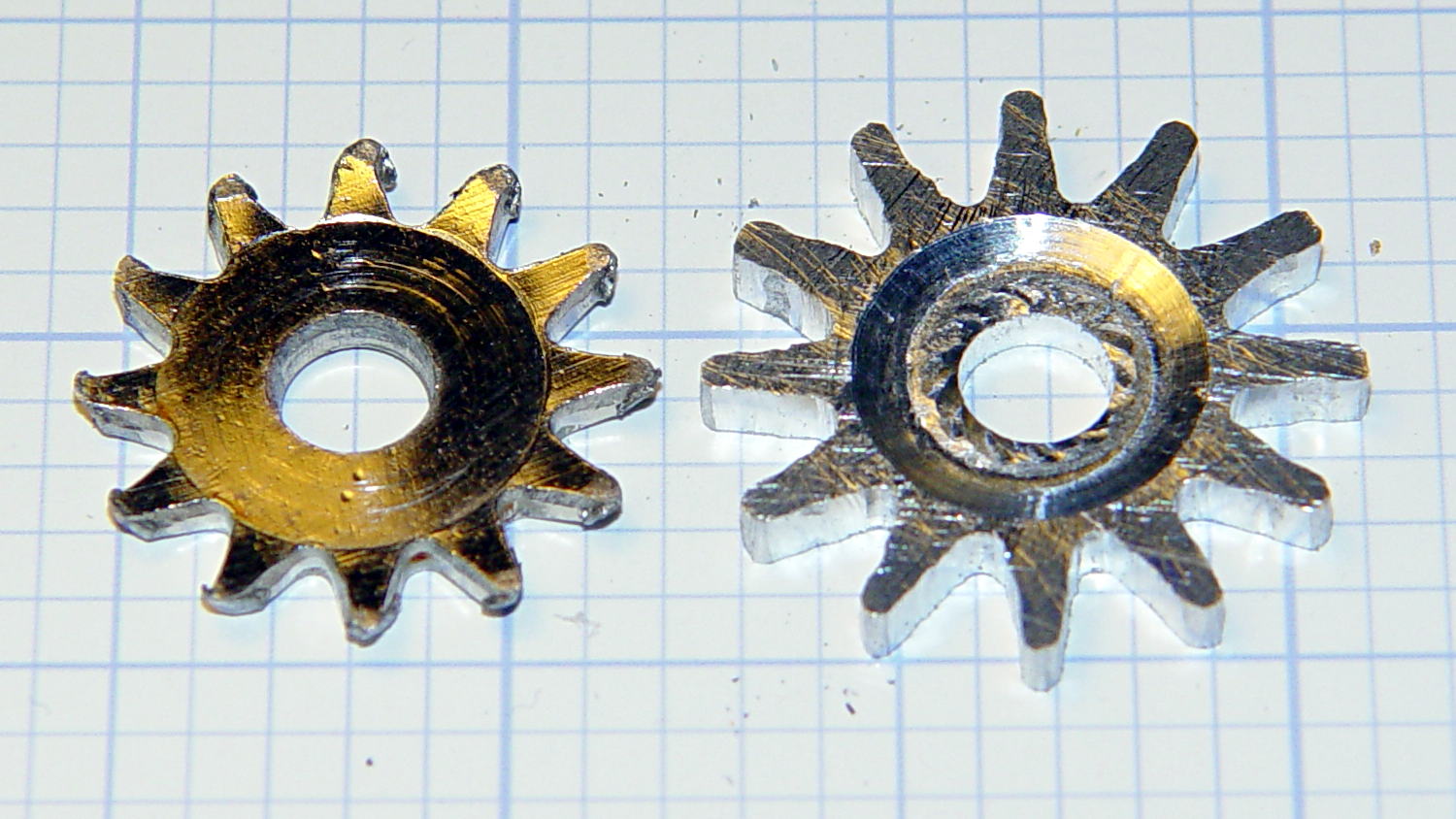
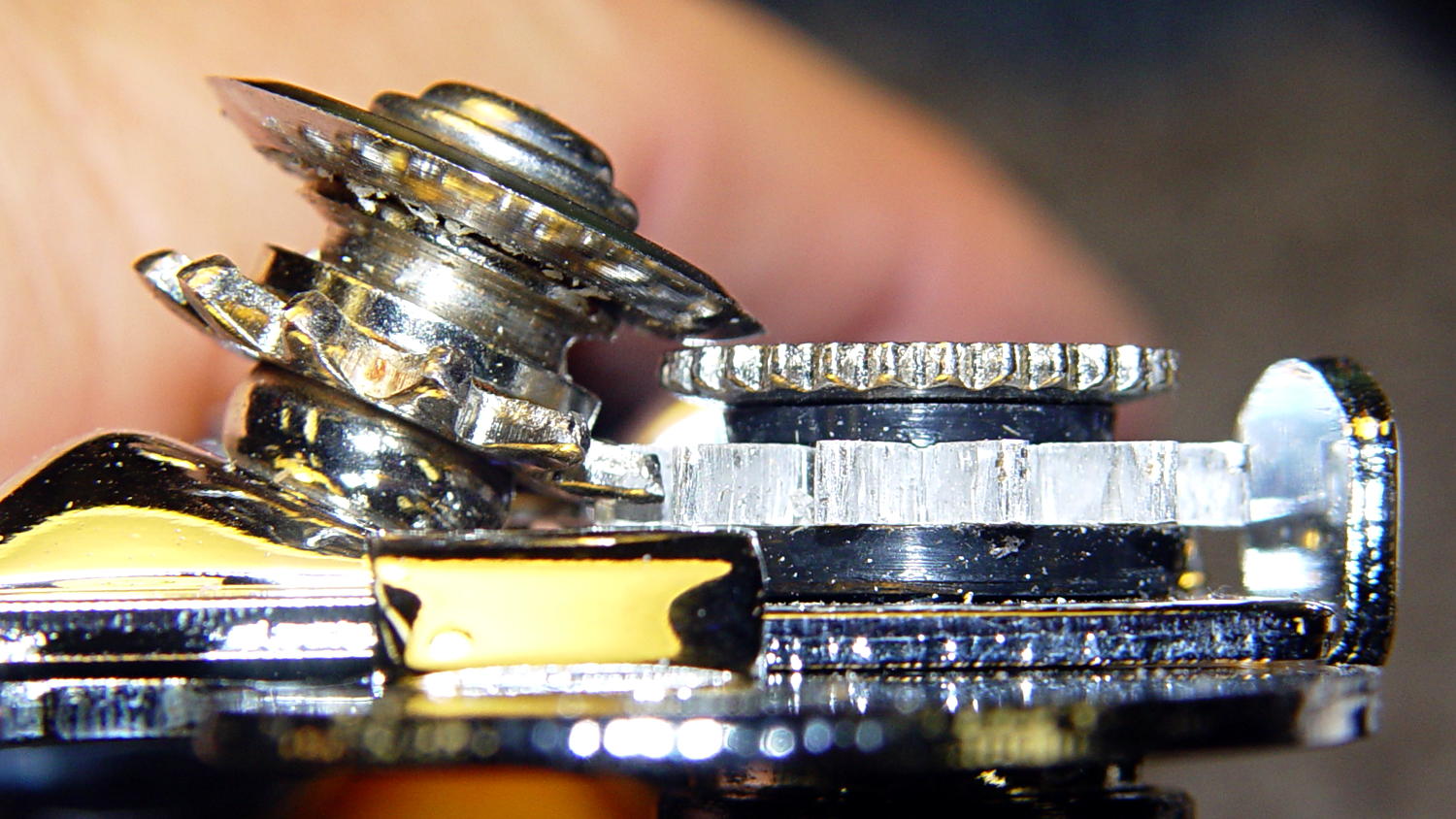
Cleaning up the wrecked gears on the can opener made it painfully obvious that I had to conjure at least one gear to get the poor thing working again:
Can opener – gears and cutters
Fortunately, those are more in the line of cogs, rather than real gears, so I decided a crude hack would suffice: drill a pattern of holes to define the openings between the teeth, file / grind the teeth reasonably smooth, and then tweak the shape to suit.
Fitting some small number-size drills between the remains of the teeth showed:
A #52 = 52.0 mil = 1.32 mm drill matched the root curvature
A #28 = 140.5 mil = 3.57 mm drill was tangent to the small drill and the tooth walls
Neither of those count as precision measurements, particularly given the ruined teeth, but they’re close enough for a first pass.
The OEM drive gear (on the right) has the teeth bent upward to mate with the cutter gear (on the left), but under normal gripping force, the teeth don’t mesh securely and tend to slide over / under / past each other. However, if I were to cut the drive gear from a metal sheet that’s thick enough to engage both the root and the crest of the cutter gear, that should prevent all the slipping & sliding. Some eyeballometric guesstimation suggested 2.5 mm would be about right and the Basement Laboratory Stockpile produced a small slab of 100 mil = 2.54 mm aluminum sheet.
However, the center part of the gear must have the same thickness as the OEM gear to keep the drive wheel at the same position relative to the cutter blade, which means a bit of pocket milling. I have some small ball burrs that seemed like they might come in handy.
A recent thread on the LinuxCNC mailing list announced Bertho Stultien’s gcmc, the G-Code Meta Compiler, and this looked like a golden opportunity to try it out. Basically, gcmc lets you write G-Code programs in a C-like language that eliminates nearly all the horrendous syntactic noise of raw G-Code. I like it a lot and you’ll be seeing more of it around here…
The gcmc source code, down below, include a function that handles automatic tool height probing, using that simple white-goods switch. The literal() function emits whatever you hand it as text for the G-Code file, which is how you mechanize esoteric commands that gcmc doesn’t include in its repertoire. It’s basically the same as my bare G-Code probe routine, but now maintains a state variable that eliminates the need for separate first-probe and subsequent-probe entry points.
One point that tripped me up, even though I should know better: because gcmc is a compiler, it can’t read G-Code parameters that exist only when LinuxCNC (or whatever) is interpreting the G-Code. You can write parameters with values computed at compile time, but you can’t read and process them in the gcmc program.
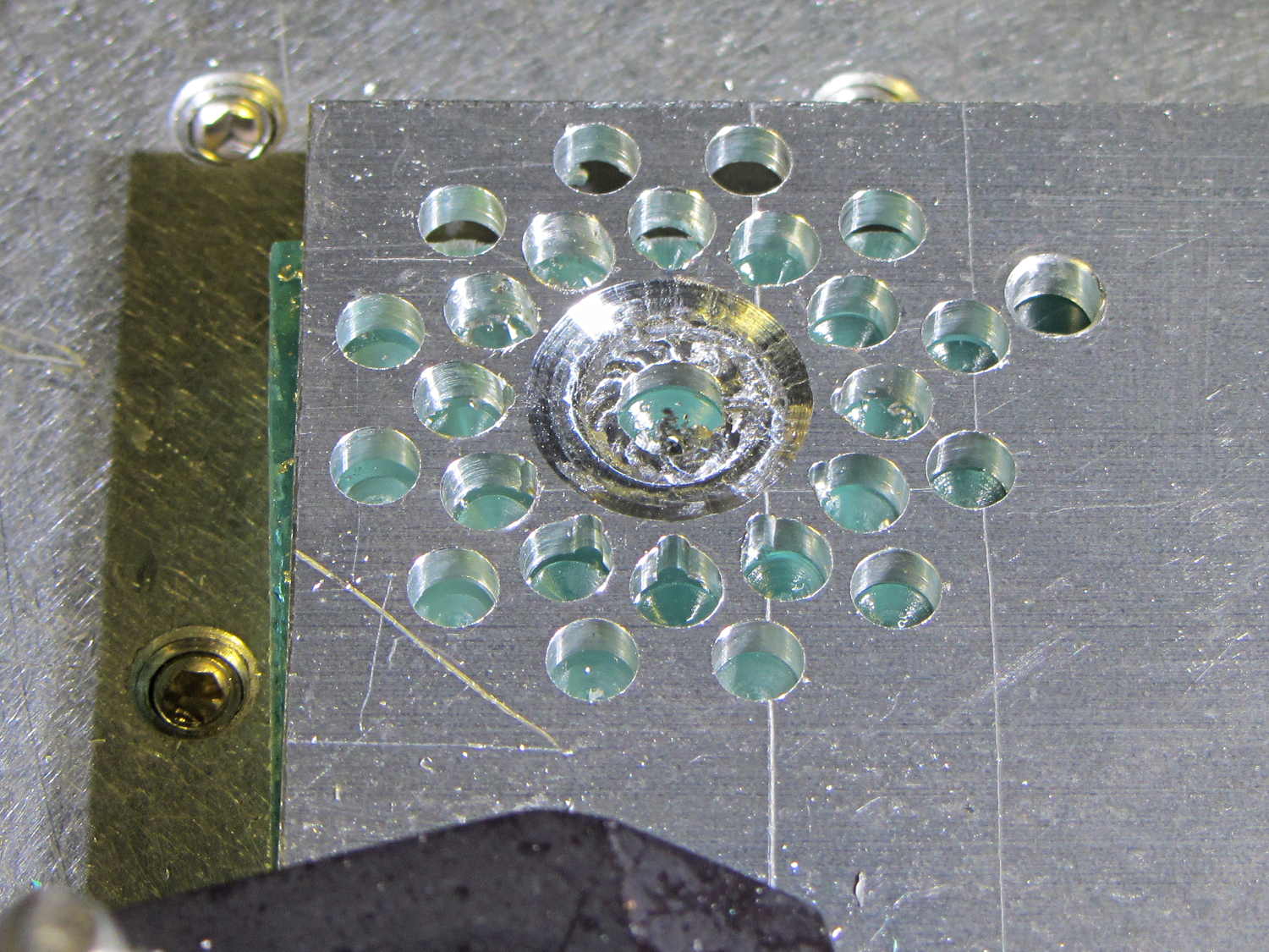
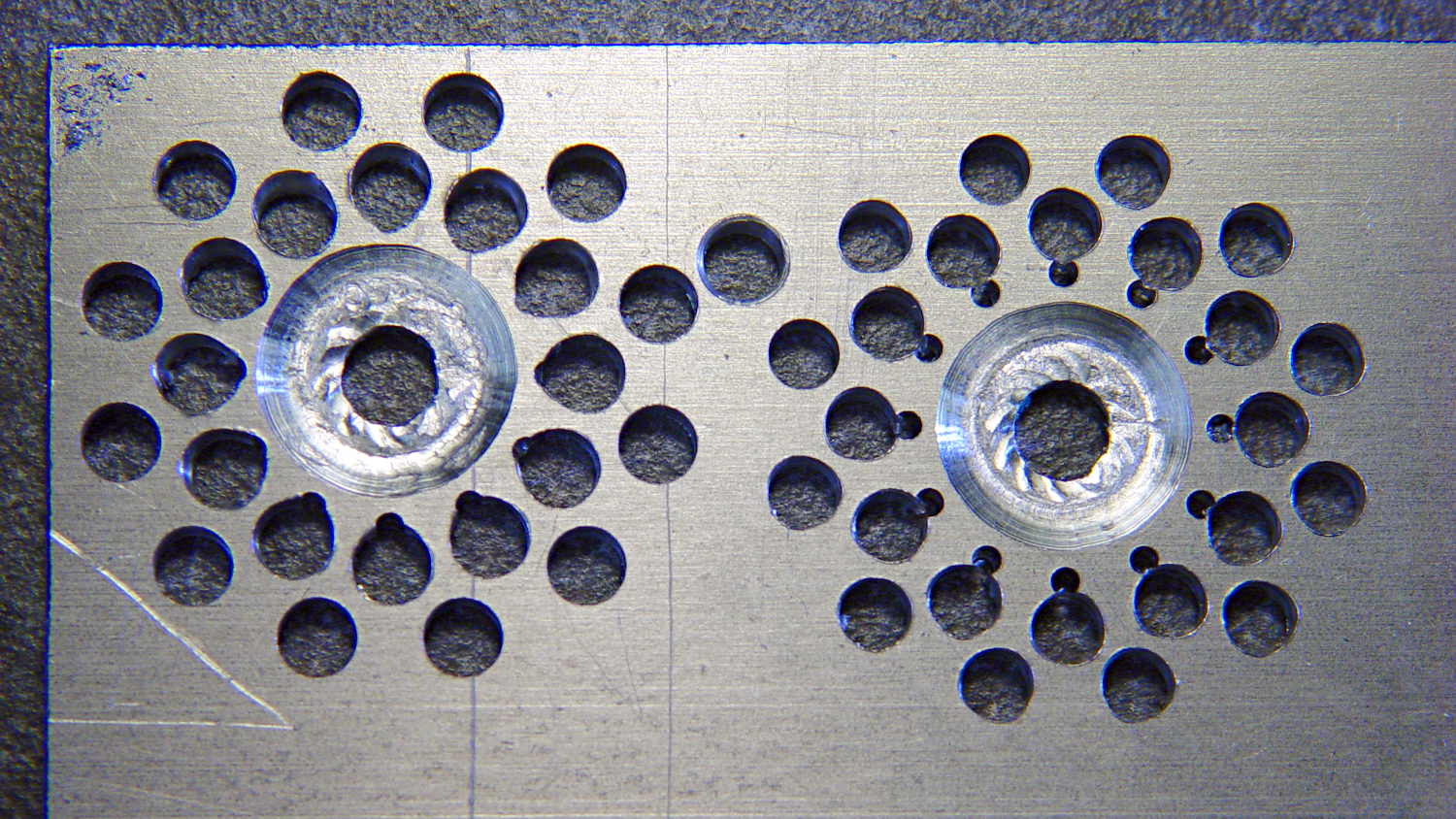
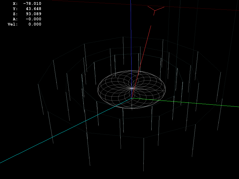
Anyhow, the first pass produced an array of holes that, as I fully expected, weren’t quite right:
Can opener gear – first hole pattern
The second pass got the root and middle holes tangent to each other:
Can opener gear – second hole pattern
It also ran a center drill pass for those tiny little holes to prevent their drill from wandering about. The other drills are about the same size as the center drill, so they’re on their own.
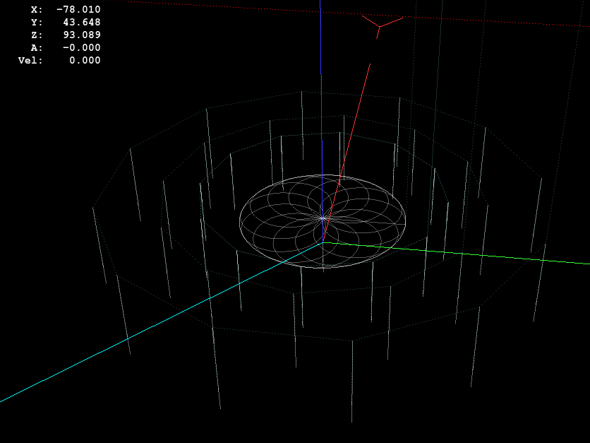
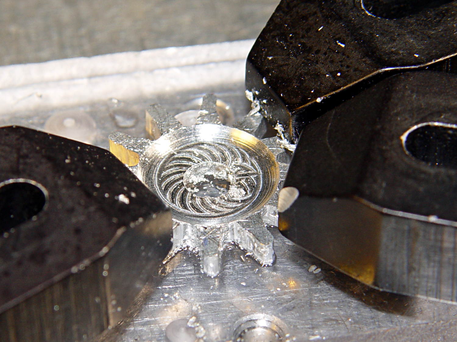
The rosette around the central hole comes from sweeping the burr in a dozen overlapping circles tangent to the outer diameter, then making a cleanup pass around the OD:
Can opener gear – 12 leaf rosette
Incidentally, that stray hole between the two patterns came from the aluminum sheet’s previous life, whatever it may have been. There are three other holes, two of which had flat washers taped to them, so your guess is as good as mine. That’s my story and I’m sticking with it.
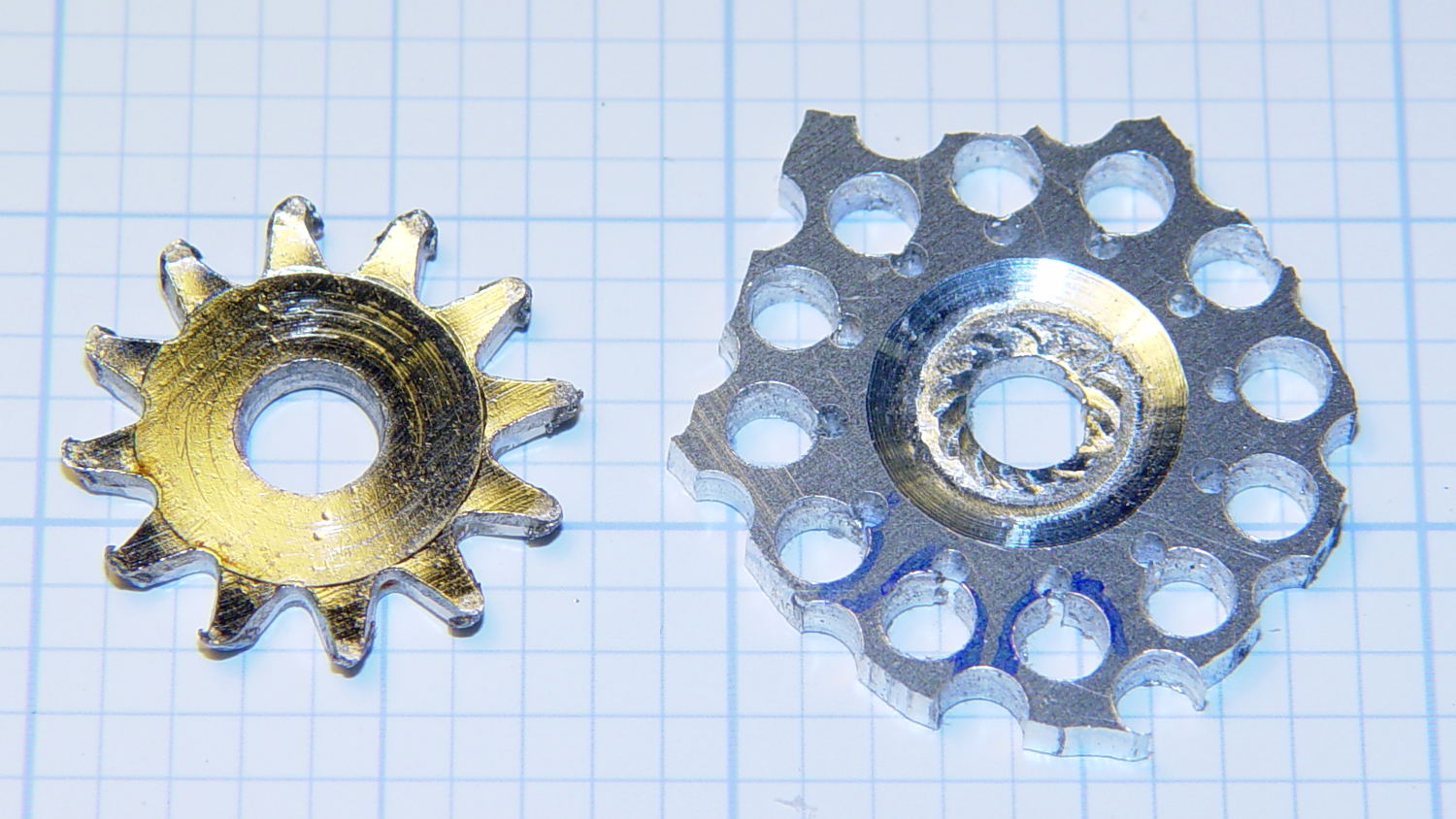
Introducing the sheet to Mr Bandsaw and cutting through the outer ring produced a bizarre snowflake:
Can opener gear – cut out
Cutting off the outer ring of holes turned the incipient gear body into a ragged shuriken:
Can opener gear – isolated
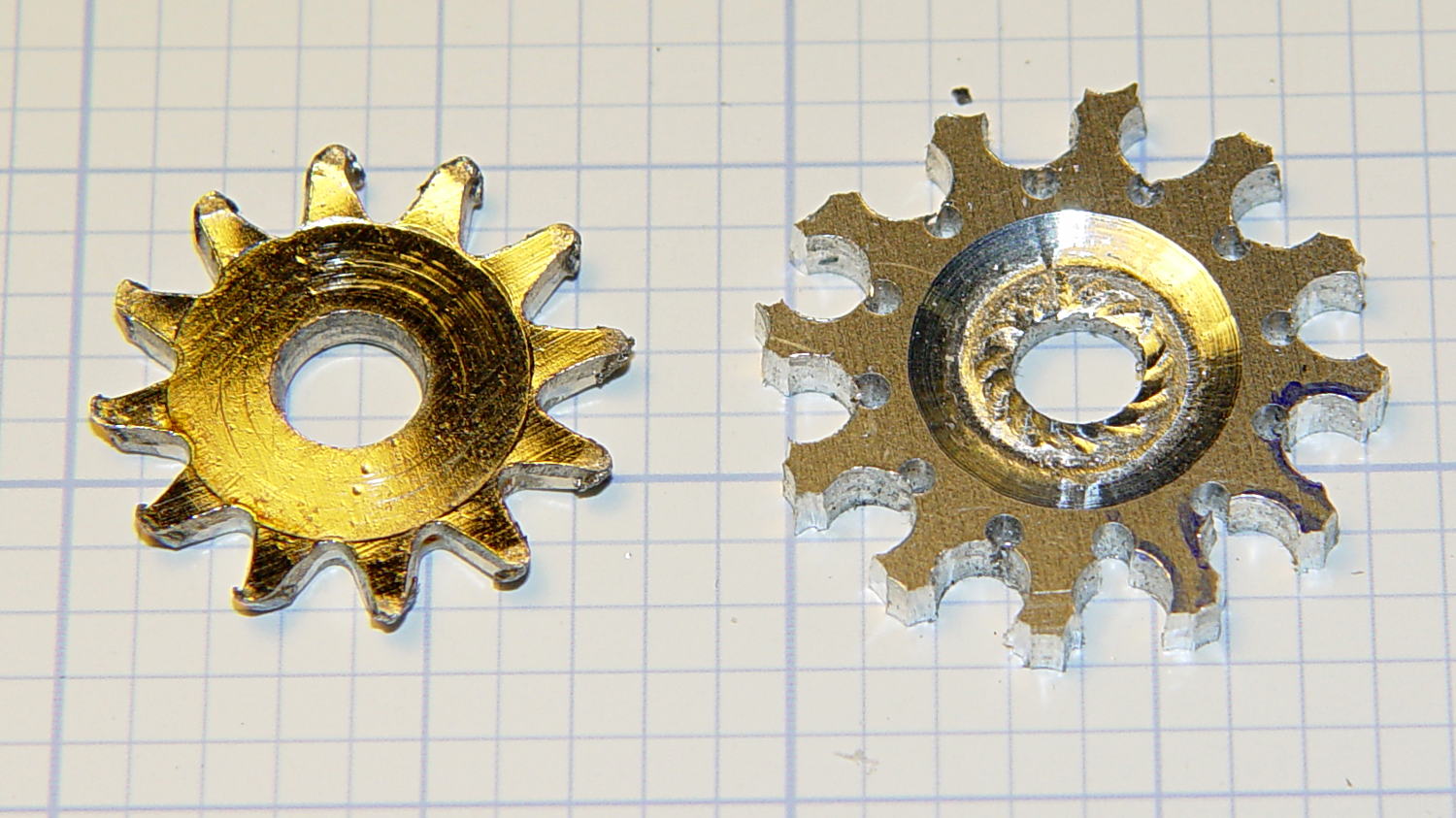
A few minutes of increasingly deft Dremel cutoff wheel work, poised on the bench vise over the shopvac nozzle to capture the dust, produced a credible gear shape:
Can opener gear – first pass
Iterating through some trial fits, re-grinds, and general fiddling showed that the center pocket was too shallow. The cutter wheel should slightly clear the drive wheel, but it’s an interference fit:
Can opener gear – trial fit
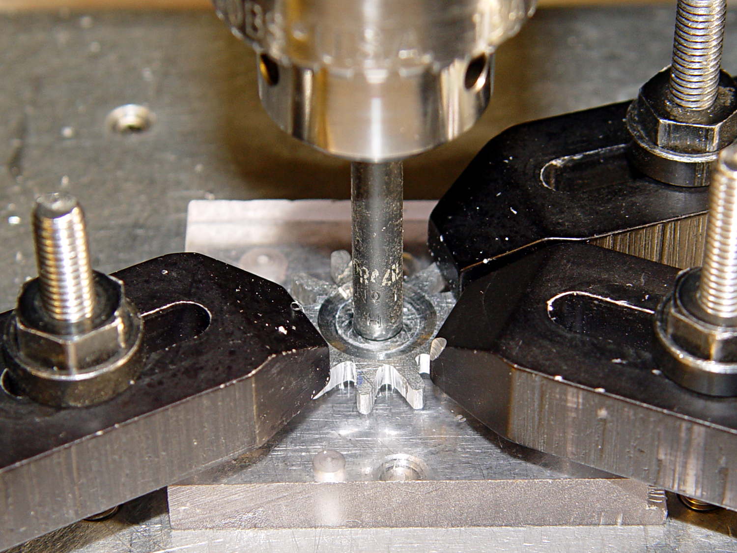
Which, of course, meant that I had to clamp the [mumble] thing back in the Sherline and re-mill the pocket. The trick is to impale it on the wrong end of a suitable drill, clamp it down, and touch off that spot as the origin:
Can opener gear – re-centering
I took the opportunity to switch to a smaller ball and make 16 little circles to clear the pocket:
Can Opener Gear – 16 leaf rosette
Now that’s better:
Can opener gear – deeper pocket
Another trial fit showed that everything ended up in the right place:
Can opener gear – final fit
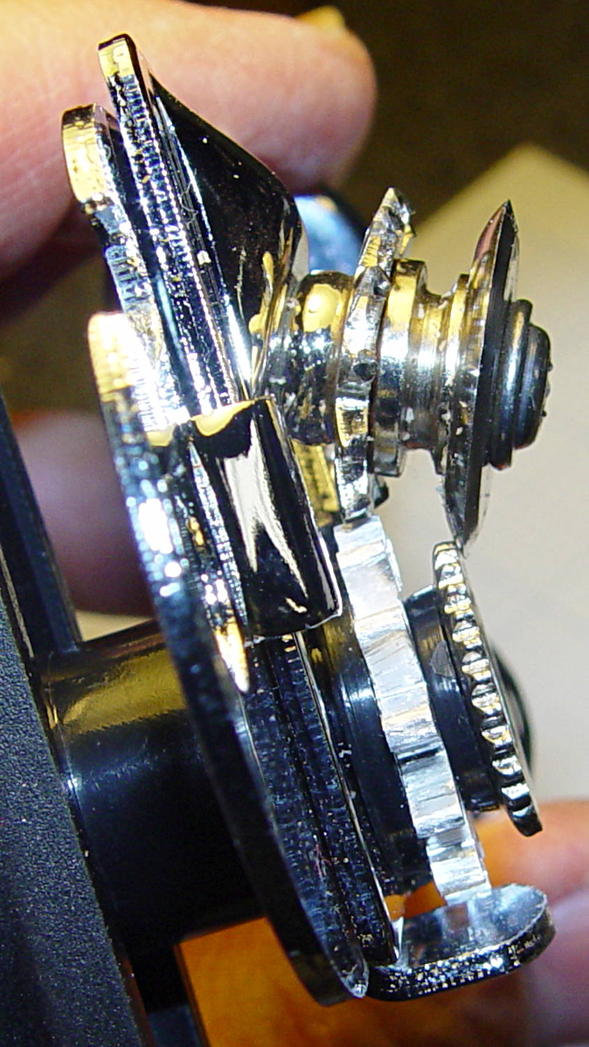
I gave it a few cranks, touched up any cogs that clashed with the (still misshapen) cutter gear, applied it to a randomly chosen can, and it worked perfectly:
Squeeze the levers to easily punch through the lid
Crankety crank on the handle, while experiencing none of the previous drama
The severed lid falls into the can
Which is exactly how it’s supposed to work. What’s so hard about that?
What you can’t see in that picture is the crest of the lowest cutter gear tooth fitting just above the bottom of the drive gear root. Similarly, the crest of the highest drive gear tooth remains slightly above the cutter root. That means the cutter gear teeth always engage the drive gear, there’s no slipping & sliding, and it’s all good.
Aluminum isn’t the right material for a gear-like object meshed with a steel counterpart, but it’s easy to machine on a Sherline. I’ll run off a few more for show-n-tell and, if when this one fails, I’ll have backup.
The gcmc source code:
// Can opener drive gears
//	Ed Nisley KE4ZNU - February 2014
//	Sherline CNC mill with tool height probe
//	XYZ touchoff origin at center on fixture surface

DO_DRILLCENTER	= 1;
DO_MILLCENTER	= 1;
DO_DRILLINNER	= 1;
DO_DRILLOUTER	= 1;
DO_DRILLTIPS	= 1;

//----------
// Overall dimensions

GearThick = 2.54;			// overall gear thickness
GearCenterThick = 1.75;		// thickness of gear center

GearTeeth = 12;				// number of teeth!
ToothAngle = 360deg/GearTeeth;
GearOD = 22.0;				// tooth tip
GearID = 13.25;				// tooth root

SafeZ = 20.0;				// guaranteed to clear clamps
TravelZ = GearThick + 1.0;	// guaranteed to clear plate

//----------
// Tool height probe
//	Sets G43.1 tool offset in G-Code, so our Z=0 coordinate always indicates the touchoff position

ProbeInit = 0;					// 0 = not initialized, 1 = initialized
ProbeSpeed = 400.0mm;
ProbeRetract = 1.0mm;

PROBE_STAY = 0;					// remain at probe station
PROBE_RESTORE = 1;				// return to previous location after probe

function ProbeTool(RestorePos) {

local WhereWasI;

	WhereWasI = position();

	if (ProbeInit == 0) {		// probe with existing tool to set Z=0 as touched off
		ProbeInit++;
		literal("#<_Probe_Speed> = ",to_none(ProbeSpeed),"\n");
		literal("#<_Probe_Retract> = ",to_none(ProbeRetract),"\n");
		literal("#<_ToolRefZ> = 0.0 \t; prepare for first probe\n");
		ProbeTool(PROBE_STAY);
		literal("#<_ToolRefZ> = #5063 \t; save touchoff probe point\n");
		literal("G43.1 Z0.0 \t; set zero offset = initial touchoff\n");
	}
	elif (ProbeInit == 1) {		// probe with new tool, adjust offset accordingly
		literal("G49 \t; clear tool length comp\n");
		literal("G30 \t; move over probe switch\n");
		literal("G59.3 \t; use coord system 9\n");
		literal("G38.2 Z0 F#<_Probe_Speed> \t; trip switch on the way down\n");
		literal("G0 Z[#5063 + #<_Probe_Retract>] \t; back off the switch\n");
		literal("G38.2 Z0 F[#<_Probe_Speed> / 10] \t; trip switch slowly\n");
		literal("#<_ToolZ> = #5063 \t; save new tool length\n");
		literal("G43.1 Z[#<_ToolZ> - #<_ToolRefZ>] \t; set new length\n");
		literal("G54 \t; return to coord system 0\n");
		literal("G30 \t; return to safe level\n");
	}
	else {
		error("*** ProbeTool sees invalid ProbeInit: ",ProbeInit);
		comment("debug,*** ProbeTool sees invalid ProbeInit: ",ProbeInit);
		ProbeInit = 0;
	}

	if (RestorePos == PROBE_RESTORE) {
		goto(WhereWasI);
	}

}

//----------
// Utility functions

function WaitForContinue(MsgStr) {
	comment(MsgStr);
	pause();
}

function CueToolChange(MsgStr) {
	literal("G0 Z" + SafeZ + "\n");
	literal("G30\n");
	WaitForContinue(MsgStr);
}

function ToolChange(Info,Name) {
	CueToolChange("msg,Insert " + to_mm(Info[TOOL_DIA]) + " = " + to_in(Info[TOOL_DIA]) + " " + Name);
	ProbeTool(PROBE_STAY);

	WaitForContinue("msg,Set spindle to " + Info[TOOL_SPEED] + " rpm");
	feedrate(Info[TOOL_FEED]);
}

function GetAir() {
	goto([-,-,SafeZ]);
}

//-- compute drill speeds & feeds based on diameter
//		rule of thumb is 100 x diameter at 3000 rpm for real milling machines
//		my little Sherline's Z axis can't produce enough thrust for that!

MaxZFeed = 600.0mm;				// fastest possible Z feed

TOOL_DIA = 0;					// Indexes into DrillParam() result
TOOL_SPEED = 1;					//  spindle RPM
TOOL_FEED = 2;					//	linear feed
TOOL_TIP = 3;					//	length of 118 degreee drill tip

function DrillParam(Dia) {
local RPM,Feed,Tip,Data,Derating;

	Derating = 0.25;			// derate from (100 x diameter) max feed

	RPM = 3000.0;				// default 3 k rpm

	Feed = Derating * (100.0 * Dia);
	if (Feed > MaxZFeed) {
		RPM *= (MaxZFeed / Feed);	//  scale speed downward to fit
		Feed = MaxZFeed;
	}

	Tip = (Dia/2) * tan(90deg - 118deg/2);
	Data = [Dia,RPM,Feed,Tip];

	message("DrillParam: ",Data);
	return Data;
}

//-- peck drilling cycle

function PeckDrill(Endpt,Retract,Peck) {
	literal("G83 X",to_none(Endpt[0])," Y",to_none(Endpt[1])," Z",to_none(Endpt[2]),
			" R",to_none(Retract)," Q",to_none(Peck),"\n");
}

//----------
// Make it happen

literal("G99\t;  retract to R level, not previous Z\n");

WaitForContinue("msg,Verify: G30 position in G54 above tool change switch?");

WaitForContinue("msg,Verify: fixture origin XY touched off at center of gear?");

WaitForContinue("msg,Verify: Z touched off on top surface at " + GearThick + "?");
ProbeTool(PROBE_STAY);

//-- Drill center hole

if (DO_DRILLCENTER) {

	DrillData = DrillParam(5.0mm);
	ToolChange(DrillData,"drill");

	goto([0,0,-]);
	goto([-,-,TravelZ]);

	drill([0,0,-1.5*DrillData[TOOL_TIP]],TravelZ,DrillData[TOOL_DIA]);
	GetAir();

}

//-- Drill inner ring

if (DO_DRILLINNER) {

	DrillData = DrillParam(1.32mm);

	RingRadius = GearID/2.0 + DrillData[TOOL_DIA]/2.0;		// center of inner ring holes
	HolePosition = [RingRadius,0mm,-1.5*DrillData[TOOL_TIP]];

//	but first, center-drill to prevent drifting

	CDData = DrillParam(1.00mm);			// pretend it's a little drill
	CDData[TOOL_FEED] = 100mm;				//  ... use faster feed

	CDPosition = HolePosition;				// use center drill coordinates
	CDPosition[2] = GearThick - 0.25mm;		//  ... just below surface

	ToolChange(CDData,"center drill");

	goto([0,0,-]);
	goto([-,-,TravelZ]);

	for (Tooth = 0 ; Tooth < GearTeeth ; Tooth++) {
		drill(CDPosition,TravelZ,2*TravelZ);		// large increment ensures one stroke
		CDPosition = rotate_xy(CDPosition,ToothAngle);
	}

//	now drill the holes

	ToolChange(DrillData,"drill");

	goto([0,0,-]);
	goto([-,-,TravelZ]);

	for (Tooth = 0 ; Tooth < GearTeeth ; Tooth++) {
		PeckDrill(HolePosition,TravelZ,DrillData[TOOL_DIA]);
		HolePosition = rotate_xy(HolePosition,ToothAngle);
	}

	GetAir();

}

//-- Mill center recess

if (DO_MILLCENTER) {

	MillData = [4.50mm,3000,250.0mm,0.0mm];			// spherical ball burr

	Delta = GearThick - GearCenterThick;							// depth to be milled away
	Inset = sqrt(2.0*Delta*(MillData[TOOL_DIA]/2) - pow(Delta,2));	// toll axis to milled edge

	ToolChange(MillData,"ball burr");

	goto([0,0,-]);							// above central hole
	goto([0,0,GearThick]);					// vertically down to flush with surface
	move([0,0,GearCenterThick]);			// into gear blank

	for (Angle = 0.0deg; Angle < 360.0deg; Angle+=360.0deg/16) {	// clear interior
		circle_cw((GearID/2 - Inset)/2,Angle);
	}

	move_r([(GearID/2 - Inset),0.0,0.0]);							// clean rim
	circle_ccw([0.0,0.0,GearCenterThick],2);

	GetAir();

}

//-- Drill outer ring

if (DO_DRILLOUTER) {

	RingRadius += DrillData[TOOL_DIA]/2;		// at OD of inner ring holes

	DrillData = DrillParam(3.18mm);
	RingRadius += DrillData[TOOL_DIA]/2.0;		// center of outer ring holes
	HolePosition = [RingRadius,0mm,-1.5*DrillData[TOOL_TIP]];

	ToolChange(DrillData,"drill");

	for (Tooth = 0 ; Tooth < GearTeeth ; Tooth++) {
		PeckDrill(HolePosition,TravelZ,DrillData[TOOL_DIA]);
		HolePosition = rotate_xy(HolePosition,ToothAngle);
	}

	GetAir();

}

//-- Drill to locate gear tooth tip end

if (DO_DRILLTIPS) {

	DrillData = DrillParam(4.22mm);

	RingRadius = GearOD/2.0 + DrillData[TOOL_DIA]/2.0;		// tangent to gear tooth tip
	HolePosition = [RingRadius,0mm,-1.5*DrillData[TOOL_TIP]];
	HolePosition = rotate_xy(HolePosition,ToothAngle/2);	// align to tooth

	ToolChange(DrillData,"drill");

	for (Tooth = 0 ; Tooth < GearTeeth ; Tooth++) {
		PeckDrill(HolePosition,TravelZ,DrillData[TOOL_DIA]);
		HolePosition = rotate_xy(HolePosition,ToothAngle);
	}

	GetAir();

}

literal("G30\n");
comment("msg,Done!");
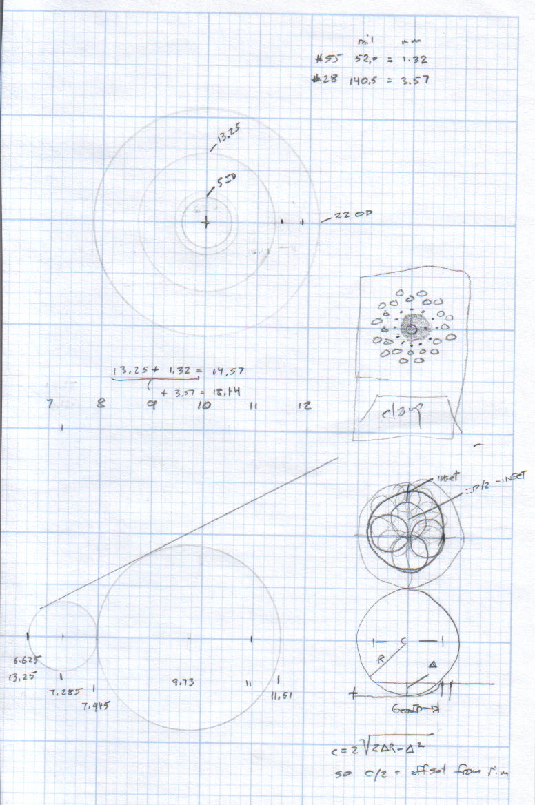
The original doodle that suggested the possibility:
Can Opener Gears – Doodle 1
The chord equation at the bottom shows how to calculate the offset for the ball burr, although it turns out there’s no good way to measure the cutting diameter of the burr and it’s not really spherical anyway.
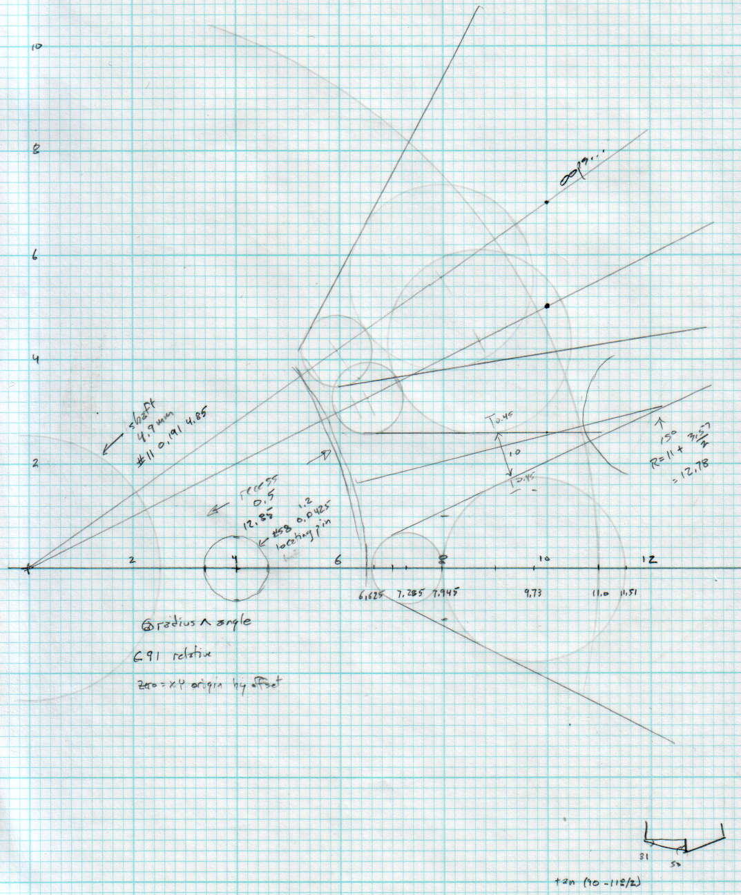
A more detailed doodle with the key line at a totally bogus angle:
Can Opener Gears – Doodle 2
The diagram in the lower right corner shows how you figure the length of the tip on a 118° drill point, which you add to the thickness of the plate in order to get a clean hole.
The first convert normalizes the grayscale file and produces a PNG file in a standard format.
The next two convert operations translate that PNG file into uncompressed PGM files with the data as ASCII text required by OpenSCAD’s surface() function. It’s not in the proper format, however, so a few lines of Bash-fu rearrange the data into DAT files; the extension is arbitrary.
Then OpenSCAD eats those files along with a bunch of configuration settings and spits out a solid model of the positive mold in STL format.
The MakePositive.scad OpenSCAD source code:
// Mold positive pattern from grayscale height map using Minkowski sum
// Ed Nisley KE4ZNU - February 2014 - adapted from cookie press, added alignment pins

//-----------------
// Mold files

fnMap = "SqWr_map.dat";					// override with -D 'fnMap="whatever.dat"'
fnPlate = "SqWr_plate.dat";				// override with -D 'fnPlate="whatever.dat"'

DotsPerMM = 3.0;						// overrride with -D DotsPerMM=number

MapHeight = 5.0;						// overrride with -D MapHeight=number

ImageX = 100;							// overrride with -D ImageX=whatever
ImageY = 100;

MapScaleXYZ = [1/DotsPerMM,1/DotsPerMM,MapHeight/255];
PlateScaleXYZ = [1/DotsPerMM,1/DotsPerMM,1.0];

echo("Press File: ",fnMap);
echo("Plate File: ",fnPlate);

echo(str("ImageX:",ImageX," ImageY: ", ImageY));
echo(str("Map Height: ",MapHeight));
echo(str("Dots/mm: ",DotsPerMM));
echo(str("Scale Map: ",MapScaleXYZ,"  Plate: ",PlateScaleXYZ));

//- Extrusion parameters - must match reality!

ThreadThick = 0.25;
ThreadWidth = 2.0 * ThreadThick;

//- Buid parameters

PlateThick = IntegerMultiple(1.0,ThreadThick);		// solid plate under press relief

PinOD = 1.75;				// locating pin diameter
PinDepth = PlateThick;		//  ... depth into bottom surface = total length/2
PinOC = 20.0;				// spacing within mold item

echo(str("Pin depth: ",PinDepth," spacing: ",PinOC));

//- Useful info

function IntegerMultiple(Size,Unit) = Unit * ceil(Size / Unit);

HoleWindage = 0.2;

Protrusion = 0.1;						// make holes & unions work correctly

MaxConvexity = 5;						// used for F5 previews in OpenSCAD GUI

ZFuzz = 0.2;							// numeric chaff just above height map Z=0 plane

//-----------------
// Import plate height map, slice off a slab to define outline

module Slab(Thick=1.0) {
	intersection() {
		translate([0,0,Thick/2])
			cube([2*ImageX,2*ImageY,Thick],center=true);
		scale(PlateScaleXYZ)
			difference() {
				translate([0,0,-ZFuzz])
					surface(fnPlate,center=true,convexity=MaxConvexity);
				translate([0,0,-1])
					cube([2*ImageX,2*ImageY,2],center=true);
			}
	}
}

//- Put peg grid on build surface

module ShowPegGrid(Space = 10.0,Size = 1.0) {

	Range = floor(50 / Space);

	for (x=[-Range:Range])
	  for (y=[-Range:Range])
		translate([x*Space,y*Space,Size/2])
			%cube(Size,center=true);
}

//-- convert cylinder to low-count polygon

module PolyCyl(Dia,Height,ForceSides=0) {			// based on nophead's polyholes

  Sides = (ForceSides != 0) ? ForceSides : (ceil(Dia) + 2);

  FixDia = Dia / cos(180/Sides);

  cylinder(r=(FixDia + HoleWindage)/2,
           h=Height,
	   $fn=Sides);
}

//-- Locating pin hole with glue recess
//  Default length is two pin diameters on each side of the split

module LocatingPin(Dia=PinOD,Len=0.0) {

	PinLen = (Len != 0.0) ? Len : (4*Dia);

	translate([0,0,-ThreadThick])
		PolyCyl((Dia + 2*ThreadWidth),2*ThreadThick,4);

	translate([0,0,-2*ThreadThick])
		PolyCyl((Dia + 1*ThreadWidth),4*ThreadThick,4);

	translate([0,0,-(Len/2 + ThreadThick)])
		PolyCyl(Dia,(Len + 2*ThreadThick),4);

}

//- Build it

//ShowPegGrid();

echo("Building mold");
union() {
	difference() {
		Slab(PlateThick + Protrusion);
		for (i=[-1,1])
			translate([0,i*PinOC/2,0])
				rotate(180/4) LocatingPin(Len=2*PinDepth);
	}
	translate([0,0,PlateThick])							// cookie press height map
		scale(MapScaleXYZ)
		difference() {
			translate([0,0,-ZFuzz])
				surface(fnMap,center=true,convexity=MaxConvexity);
			translate([0,0,-1])
				cube([2*ImageX,2*ImageY,2],center=true);
		}
}
The plate holds the molds in place, perhaps with tapeless sticky, while you’re slathering silicone goop to make the negative mold:
Tux Positive Mold Framework – 2×3 array
As you might expect, the OpenSCAD file that generates the plate-with-holes can also embed the positive molds atop the plate, so you could get a solid (well, infilled at 20%) chunk of plastic without attaching the molds. I’d rather do the plate separately from the molds, so you can recycle the plate for many different molds. Your mileage may vary.
The Positive Mold Framework.scad OpenSCAD source code:
// Positive mold framework for chocolate slabs
// Ed Nisley - KE4ZNU - January 2014

Layout = "FramePins";		// FramePins FrameMolds Pin

//- Extrusion parameters must match reality!
//  Print with 2 shells and 3 solid layers

ThreadThick = 0.20;
ThreadWidth = 0.40;

Protrusion = 0.1;			// make holes end cleanly

HoleWindage = 0.2;

//----------------------
// Dimensions

FileName = "Tux-positive.stl";	// overrride with -D

Molds = [2,3];					// count of molds within framework

MoldOC = [40.0,45.0];			// on-center spacing of molds
MoldSlab = 1.0;					// thickness of slab under molds

BaseThick = 5.0;

BaseSize = [(Molds[0]*MoldOC[0] + 0),(Molds[1]*MoldOC[1] + 0),BaseThick];
echo(str("Overall base: ",BaseSize));

PinOD = 1.75;					// locating pin diameter
PinLength = 2.0;				//  ... total length
PinOC = 20.0;				// spacing within mold item

//----------------------
// Useful routines

//- Put peg grid on build surface

module ShowPegGrid(Space = 10.0,Size = 1.0) {

	RangeX = floor(100 / Space);
	RangeY = floor(125 / Space);

	for (x=[-RangeX:RangeX])
		for (y=[-RangeY:RangeY])
			translate([x*Space,y*Space,Size/2])
			%cube(Size,center=true);

}

module PolyCyl(Dia,Height,ForceSides=0) {			// based on nophead's polyholes

  Sides = (ForceSides != 0) ? ForceSides : (ceil(Dia) + 2);

  FixDia = Dia / cos(180/Sides);

  cylinder(r=(FixDia + HoleWindage)/2,
           h=Height,
	   $fn=Sides);
}

// Locating pin hole with glue recess
//  Default length is two pin diameters on each side of the split

module LocatingPin(Dia=PinOD,Len=0.0) {

	PinLen = (Len != 0.0) ? Len : (4*Dia);

	translate([0,0,-ThreadThick])
		PolyCyl((Dia + 2*ThreadWidth),2*ThreadThick,4);

	translate([0,0,-2*ThreadThick])
		PolyCyl((Dia + 1*ThreadWidth),4*ThreadThick,4);

	translate([0,0,-(Len/2 + ThreadThick)])
		PolyCyl(Dia,(Len + 2*ThreadThick),4);

}

module LocatingPins(Length) {
	for (i=[-1,1])
	translate([0,i*PinOC/2,0])
		rotate(180/4)
		LocatingPin(Len=Length);
}

//-- import a single mold item

module MoldItem() {
	import(FileName,convexity=10);
}

//-- Overall frame shape

module Frame() {

//	translate([0,0,BaseSize[2]/2])		// platform under molds
//		cube(BaseSize,center=true);

	difference() {
		hull()
			for (i=[-1,1], j=[-1,1])
				translate([i*BaseSize[0]/2,j*BaseSize[1]/2,0])
					sphere(r=BaseThick);
		translate([0,0,-BaseThick])
			cube(2*BaseSize,center=true);
	}

}

//- Build it

ShowPegGrid();

if (Layout == "Pin")
	LocatingPin(Len=PinLength);

if (Layout == "Frame")
	Frame();

if (Layout == "FramePins")
	difference() {
		Frame();

		translate([-MoldOC[0]*(Molds[0] - 1)/2,-MoldOC[1]*(Molds[1] - 1)/2,0])
			for (i=[0:Molds[0]-1],j=[0:Molds[1]-1])
				translate([i*MoldOC[0],j*MoldOC[1],BaseSize[2]])
					LocatingPins(BaseThick);
	}

if (Layout == "FrameMolds") {
	Frame();
	translate([-MoldOC[0]*(Molds[0] - 1)/2,-MoldOC[1]*(Molds[1] - 1)/2,0])
		for (i=[0:Molds[0]-1],j=[0:Molds[1]-1])
			translate([i*MoldOC[0],j*MoldOC[1],BaseThick - MoldSlab + Protrusion])
			MoldItem();
}
And then it’s time to pour some chocolate… which someone else knows how to do much better than I!
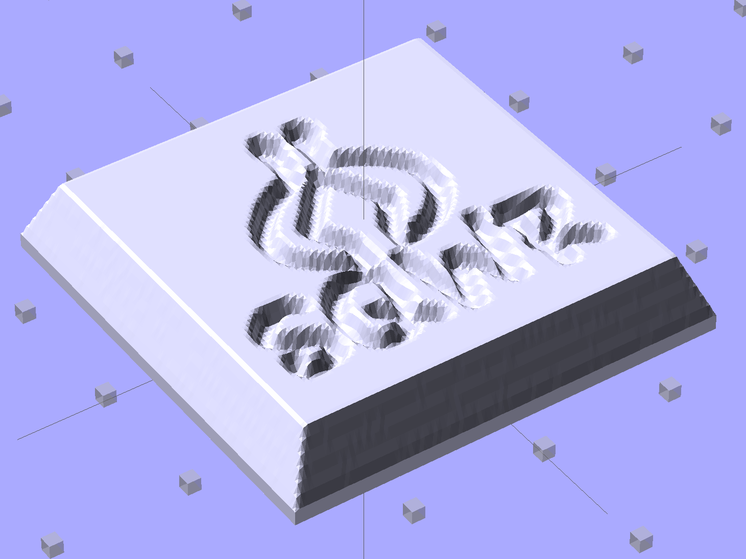
Given an STL file generated from a height map image, import it into OpenSCAD:
SqWr solid model – OpenSCAD – oblique view
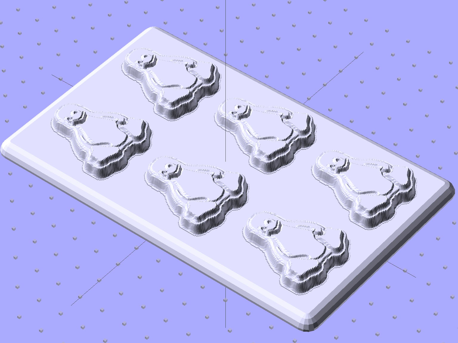
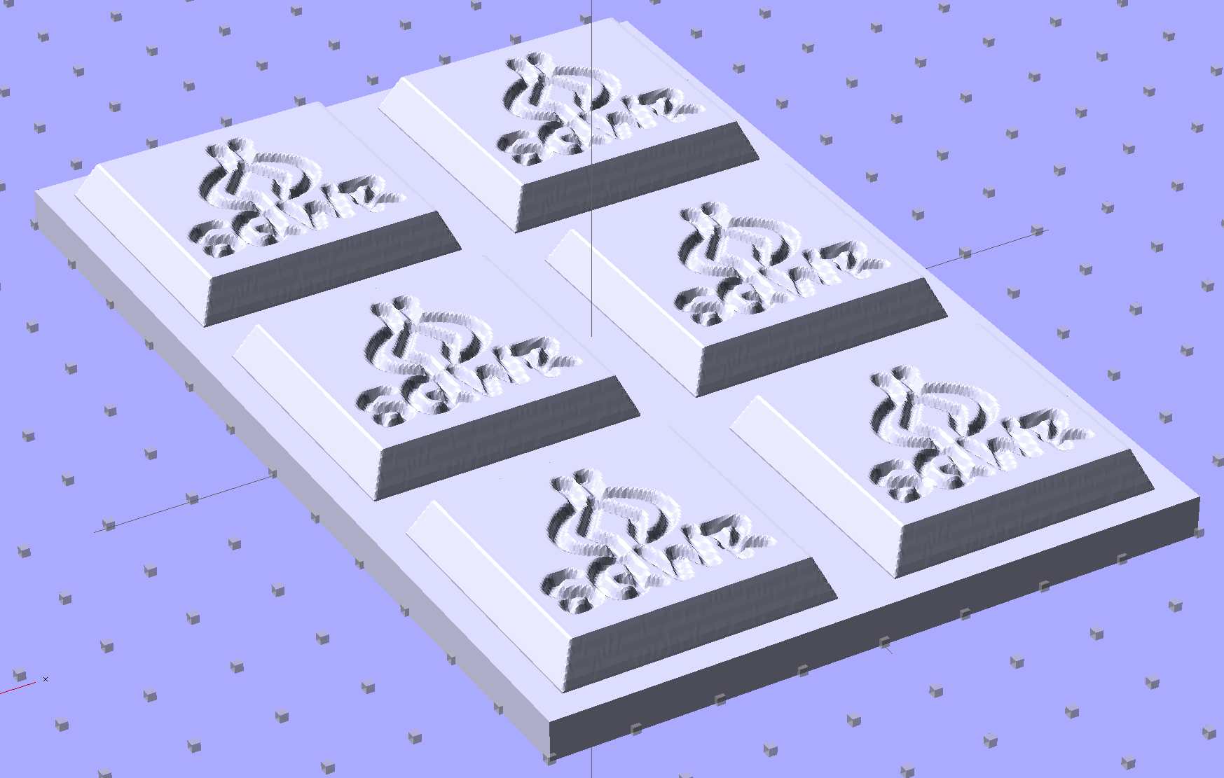
Then slide a plate under six copies to produce a positive model for a casting mold:
SqWr Positive Mold Framework – 2×3
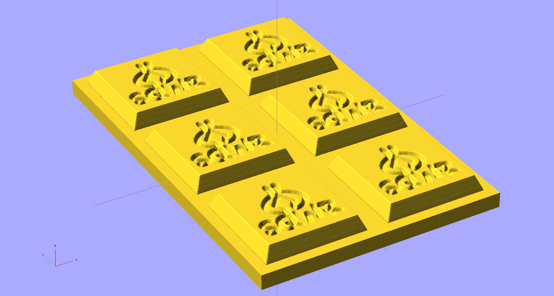
This is one of the few cases where the compiled-and-rendered version looks better, as though you’d shrink-wrapped it in gold foil:
SqWr Positive Mold Framework – 2×3 – gold
The height map STLs each have a bazillion tiny facets that take forever-and-a-day (well, the better part of half an hour for this set) to render, not to mention that the whole array would take two hours to print… and then be used once or twice to produce the flexy silicone negative mold.
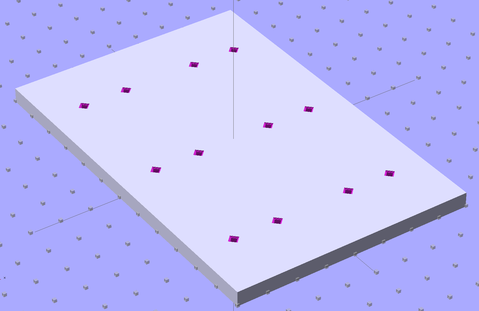
So it’s better to have a generic frame with alignment pin holes that you print once:
SqWr Positive Mold Framework – 2×3 pins
Better yet, just CNC-drill those holes in a nice, flat acrylic / polycarbonate slab.
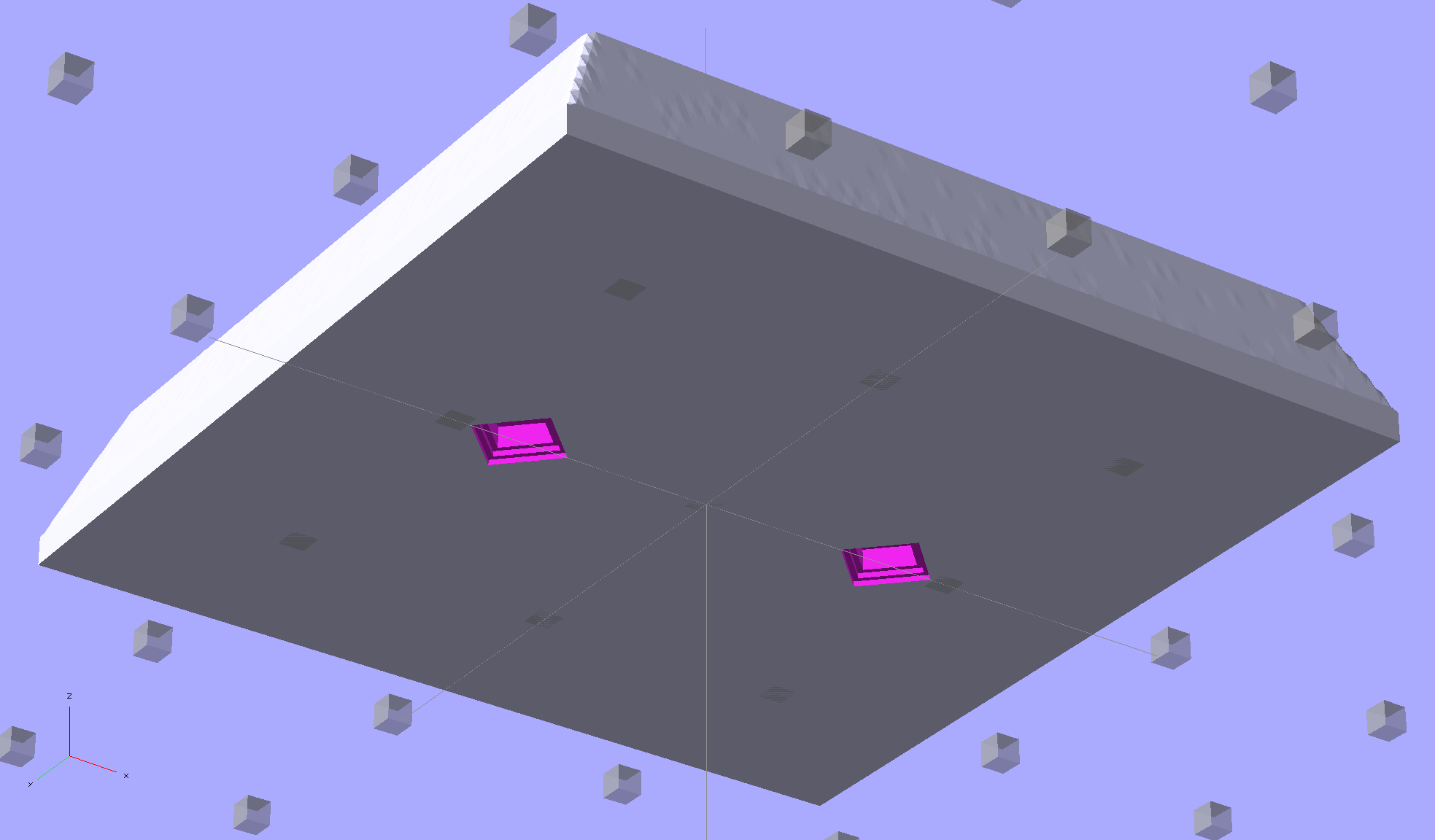
The OpenSCAD program can punch matching holes in the back of the small mold:
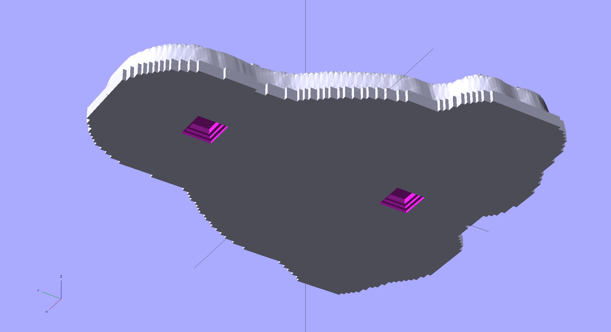
SqWr solid model – OpenSCAD – oblique bottom
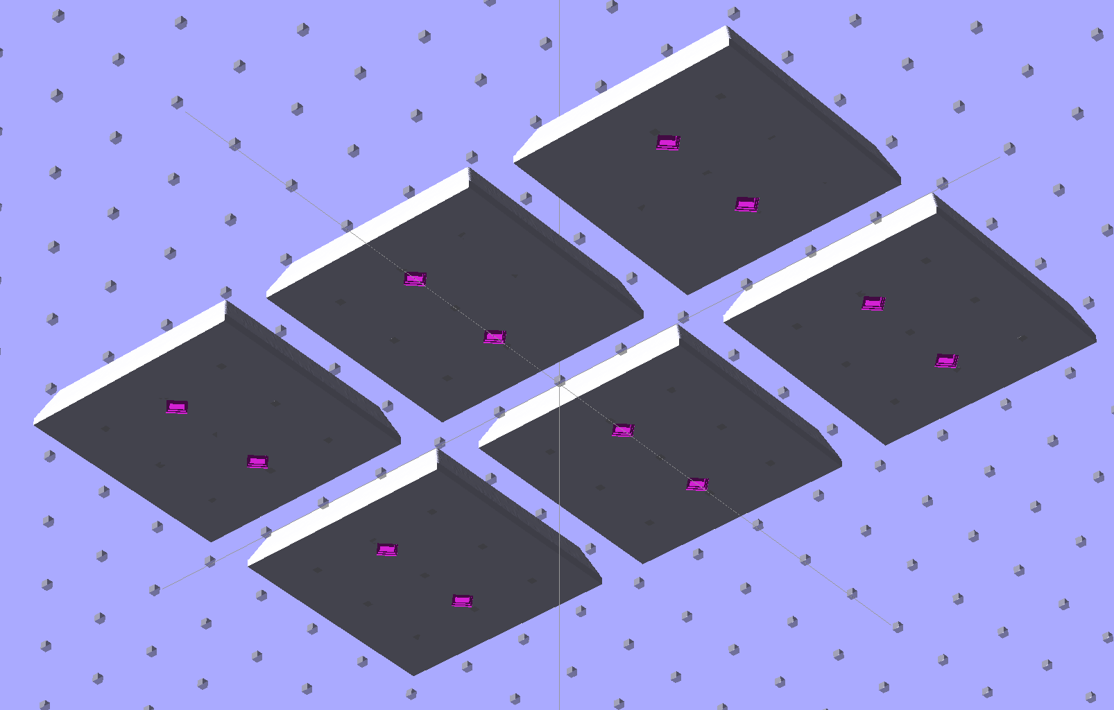
Or you could print out an array of the things with holes:
SqWr solid model – 2×3 array – bottom
It’s not clear having OpenSCAD labor for half an hour to generate and emit a single STL file spanning all six molds is a win. Given that you don’t care about the mold-to-mold spacing, having Slic3r duplicate the same small STL file half a dozen (or more!) times would probably be a net win.
There’s no reason the OpenSCAD program that creates the original STL from the height map image can’t punch alignment pin holes, too, which would avoid this import-and-recompile step. If you’re going with a CNC-drilled plate, then it would make even more sense to not have a pair of OpenSCAD programs.
Anyhow.
Apply a handful of small molds to the backing plate with tapeless sticky, butter it up with mold release agent, slather on silicone putty, flip it over to produce a smooth surface “under” the small molds (so you can rest it flat on a table when pouring molten chocolate into the cavities), cure, peel, and you’d get a pretty good negative mold.
This may not make any practical sense, but it was easy & fun to see what’s possible…
The OpenSCAD source code:
// Positive mold framework for chocolate slabs
// Ed Nisley - KE4ZNU - January 2014

Layout = "FramePins";		// Molds FramePins FrameMolds Frame Single Pin

//- Extrusion parameters must match reality!
//  Print with 2 shells and 3 solid layers

ThreadThick = 0.20;
ThreadWidth = 0.40;

Protrusion = 0.1;			// make holes end cleanly

HoleWindage = 0.2;

//----------------------
// Dimensions

FileName = "SqWr-press.stl";	// overrride with -D

Molds = [2,3];					// count of molds within framework

MoldOC = [40.0,40.0];			// on-center spacing of molds
MoldSlab = 1.0;					// thickness of slab under molds

BaseThick = 5.0;

BaseSize = [(Molds[0]*MoldOC[0] + 0),(Molds[1]*MoldOC[1] + 0),BaseThick];
echo(str("Overall base: ",BaseSize));

PinOD = 1.75;					// locating pin diameter
PinLength = 2.0;				//  ... total length
PinSpace = 15.0;				// spacing within mold item

//----------------------
// Useful routines

//- Put peg grid on build surface

module ShowPegGrid(Space = 10.0,Size = 1.0) {

	RangeX = floor(100 / Space);
	RangeY = floor(125 / Space);

	for (x=[-RangeX:RangeX])
		for (y=[-RangeY:RangeY])
			translate([x*Space,y*Space,Size/2])
			%cube(Size,center=true);

}

module PolyCyl(Dia,Height,ForceSides=0) {			// based on nophead's polyholes

  Sides = (ForceSides != 0) ? ForceSides : (ceil(Dia) + 2);

  FixDia = Dia / cos(180/Sides);

  cylinder(r=(FixDia + HoleWindage)/2,
           h=Height,
	   $fn=Sides);
}

// Locating pin hole with glue recess
//  Default length is two pin diameters on each side of the split

module LocatingPin(Dia=PinOD,Len=0.0) {

	PinLen = (Len != 0.0) ? Len : (4*Dia);

	translate([0,0,-ThreadThick])
		PolyCyl((Dia + 2*ThreadWidth),2*ThreadThick,4);

	translate([0,0,-2*ThreadThick])
		PolyCyl((Dia + 1*ThreadWidth),4*ThreadThick,4);

	translate([0,0,-(Len/2 + ThreadThick)])
		PolyCyl(Dia,(Len + 2*ThreadThick),4);

}

module LocatingPins(Length) {
	for (i=[-1,1])
	translate([i*PinSpace/2,0,0])
		LocatingPin(Len=Length);
}

//-- import a single mold item

module MoldItem() {
	import(FileName,convexity=10);
}

//-- Overall frame shape

module Frame() {

	translate([0,0,BaseSize[2]/2])		// platform under molds
		cube(BaseSize,center=true);

}

//- Build it

ShowPegGrid();

if (Layout == "Pin")
	LocatingPin(Len=PinLength);

if (Layout == "Single")
	difference() {
		MoldItem();
		LocatingPins(PinLength);
	}

if (Layout == "Frame")
	Frame();

if (Layout == "Molds") {
	translate([-MoldOC[0]*(Molds[0] - 1)/2,-MoldOC[1]*(Molds[1] - 1)/2,0])
	for (i=[0:Molds[0]-1],j=[0:Molds[1]-1])
		translate([i*MoldOC[0],j*MoldOC[1],0])
			difference() {
				MoldItem();
				LocatingPins(PinLength);
			}
}

if (Layout == "FramePins")
	difference() {
		Frame();

		translate([-MoldOC[0]*(Molds[0] - 1)/2,-MoldOC[1]*(Molds[1] - 1)/2,0])
			for (i=[0:Molds[0]-1],j=[0:Molds[1]-1])
				translate([i*MoldOC[0],j*MoldOC[1],BaseSize[2]])
					LocatingPins(BaseThick);
	}

if (Layout == "FrameMolds") {
	Frame();
	translate([-MoldOC[0]*(Molds[0] - 1)/2,-MoldOC[1]*(Molds[1] - 1)/2,0])
		for (i=[0:Molds[0]-1],j=[0:Molds[1]-1])
			translate([i*MoldOC[0],j*MoldOC[1],BaseThick - MoldSlab + Protrusion])
			MoldItem();
}