Ed Nisley's Blog: Shop notes, electronics, firmware, machinery, 3D printing, laser cuttery, and curiosities. Contents: 100% human thinking, 0% AI slop.
Category: Science
If you measure something often enough, it becomes science
One of the battery packs powering the GPS+audio interface on our bikes has completely failed, with zero volts at the output and no charge indication. The other five chug along as well as can be expected:
Initial-brand DVD External Packs – 2013-11
The push-to-test button on Pack 4 has become increasingly erratic over the last few months, rendering the charge status LEDs mostly useless, so it has two curves: the lower capacity came directly from the bike, the higher hot off the charger.
For reference, here’s what they looked like in May 2012:
External Li-Ion packs – 2012-05
And right after they arrived:
Initial External Li-Ion packs
Given their nearly constant use and charge cycling, I’m impressed.
The trio of batteries I built for the Sony DSC-F505V two years ago faded away; that camera seems particularly hard on the batteries, perhaps because they’re two cells in parallel that don’t share well. Two of the three seem pretty well gone:
Sony NP-FS11 2011 Packs – 2013-11 tests
Back then, I bought 12 cells, built six into those batteries, and left six charged cells sitting in a bag. After rebuilding the two worst batteries with those new-old-stock cells, it seems they maintained a substantial fraction of their charge while resting in the cool and the dark:
Sony NP-FS11 2011 Cells – 2013 packs – 2013-11-24
However, the camera would regard them as discharged, because it infers charge state from voltage. Squinting at the curves, their condition after a few minutes is roughly equal to a new & freshly charged battery produces over on the right when it’s nearly discharged.
The other curves show the result after their first charge in two years: basically, full capacity. The fact that both pairs of curves come pretty close to overlaying means they’re still well matched.
Sony NP-FS11 batteries – rebuilt
The third cell isn’t up to their spec, but it’s close enough to not bother rebuilding right now: 1.2 vs 1.4 A·h.
The Kapton tape pull tabs work wonderfully well, as the rebuilt batteries fit the compartment rather more snugly than the un-hacked cases.
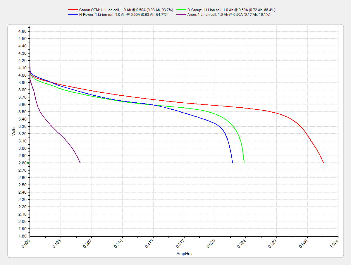
One of the junker NB-5L eBay batteries for my Canon SX-230HS pocket camera gave up, but the other two have some usable capacity left. The OEM Canon battery seems to be doing fine, perhaps because it sees a relatively low duty cycle:
The whole point of the Hall effect current sensor was to get a reasonably efficient linear LED driver that could control the LED current until the battery voltage matched the LED forward drop. Based on the preliminary firmware, it works pretty well.
With a setpoint of 160 mA, the current stabilizes around 150 mA due to the Arduino’s 0.4% PWM resolution. It steps back and forth between 150 and 190 mA as the loop bumps the PWM by one count; these scope shots came from the lower current passes.
At 8.4 V from the bench supply, the MOSFET sees about 2 V. The top trace is the drain voltage, the bottom is LED current at 50 mA/div:
VIN 8.4 V – VD ILED 50 mA-div
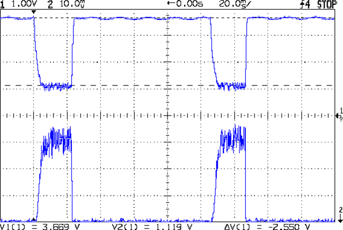
At 7.4 V, close to the nominal voltage during most of the discharge curve, the drain sees about 1 V:
VIN 7.4 V – VD ILED 50 mA-div
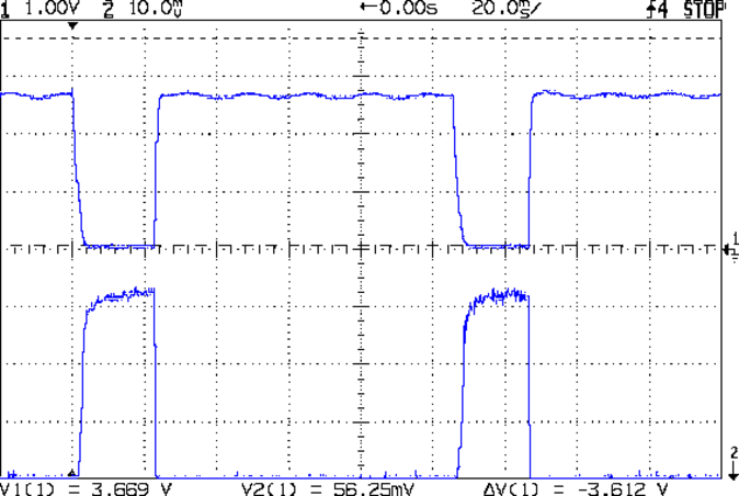
And at 6.4 V, even though the drain voltage hits zero, the current remains around 150 mA:
VIN 6.4 V – VD ILED 50 mA-div
Admittedly, down there the loop doesn’t have much in the way of control authority, but I planned to turn the lights out at about that point, anyway.
The driver efficiency is 86% at 7.4 V and it’s pretty nearly 100% at 6.4 V.
Of course, the Hall effect circuitry and Arduino Pro Mini soak up another 40 mA or so, so (assuming a 10% duty cycle) the overall efficiency is down around 70%, but that’s including the debugging LEDs and suchlike, so some tweaking is in order.
We hauled 70 pounds of apples back across the river last month:
Apple Ride – 2013-10-20
If only there were a Spackenkill Road bridge across the Hudson…
We laid the bags out on the garage floor, seeing as how they can’t go into the cold cellar with the root crops (apples give off ethylene gas, which doesn’t mix well with long-storage crops). I dropped a Hobo datalogger into one bag to record the temperatures:
Apples and air temperature
The purple trace comes from a data logger in the attic, which is as close as we have to an outside air temperature record.
Those low air temperatures suggest it’s time to move the remaining apples into the basement, as far from the root cellar as possible, as we have more nights in the teens ahead.
According to Wikipedia, Polylactic acid, a.k.a. PLA “is soluble in chlorinated solvents, hot benzene, tetrahydrofuran, and dioxane” and is not soluble in acetone, alcohol, or water.
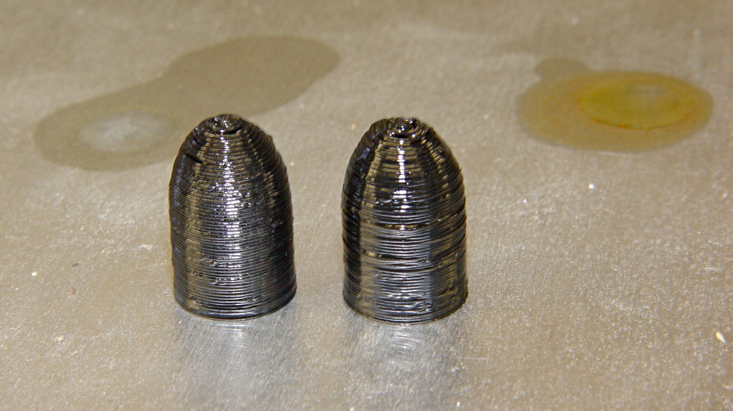
Just to see what happens, I dunked a pair of those 3D printed dummy bullets in Shooter’s Choice Gun Solvent (which has since gone obsolete) and Hoppe’s No. 9 Gun Bore Cleaner (which seems to have been reformulated several times), then let them air-dry in those background puddles:
PLA dummy bullets after solvent bath
Nothing much happened: they’re not soft or gummy, haven’t slumped, and seem undaunted.
That’s in contrast to ABS plastic, which isreadily soluble in acetone and the aromatic hydrocarbons commonly found in solvents used around firearms. Apart from that, ABS would be a slightly better choice on mechanical grounds. I’m not sure the difference really matters for most purposes, given the very wide tolerances on 3D printed objects.