The whole point of the Hall effect current sensor was to get a reasonably efficient linear LED driver that could control the LED current until the battery voltage matched the LED forward drop. Based on the preliminary firmware, it works pretty well.
With a setpoint of 160 mA, the current stabilizes around 150 mA due to the Arduino’s 0.4% PWM resolution. It steps back and forth between 150 and 190 mA as the loop bumps the PWM by one count; these scope shots came from the lower current passes.
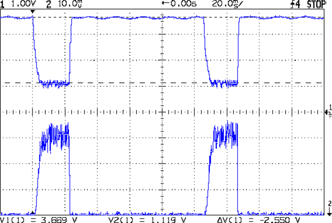
At 8.4 V from the bench supply, the MOSFET sees about 2 V. The top trace is the drain voltage, the bottom is LED current at 50 mA/div:

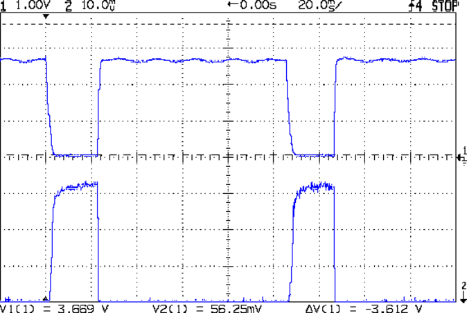
At 7.4 V, close to the nominal voltage during most of the discharge curve, the drain sees about 1 V:
And at 6.4 V, even though the drain voltage hits zero, the current remains around 150 mA:
Admittedly, down there the loop doesn’t have much in the way of control authority, but I planned to turn the lights out at about that point, anyway.
The driver efficiency is 86% at 7.4 V and it’s pretty nearly 100% at 6.4 V.
Of course, the Hall effect circuitry and Arduino Pro Mini soak up another 40 mA or so, so (assuming a 10% duty cycle) the overall efficiency is down around 70%, but that’s including the debugging LEDs and suchlike, so some tweaking is in order.
