The Smell of Molten Projects in the Morning

Ed Nisley's Blog: Shop notes, electronics, firmware, machinery, 3D printing, laser cuttery, and curiosities. Contents: 100% human thinking, 0% AI slop.

Category: Science

If you measure something often enough, it becomes science

  • M2 Platform Leveling

    This doesn’t happen very often, but, after a few road trips and some jostling around, the M2’s platform was definitely out of alignment: the first layer came out generally too thin, with the X-Y+ quadrant very much too thin.

    I tried a quick and dirty adjustment that didn’t produce meaningful results, then broke out the Starrett Taper Gauge and did it right.

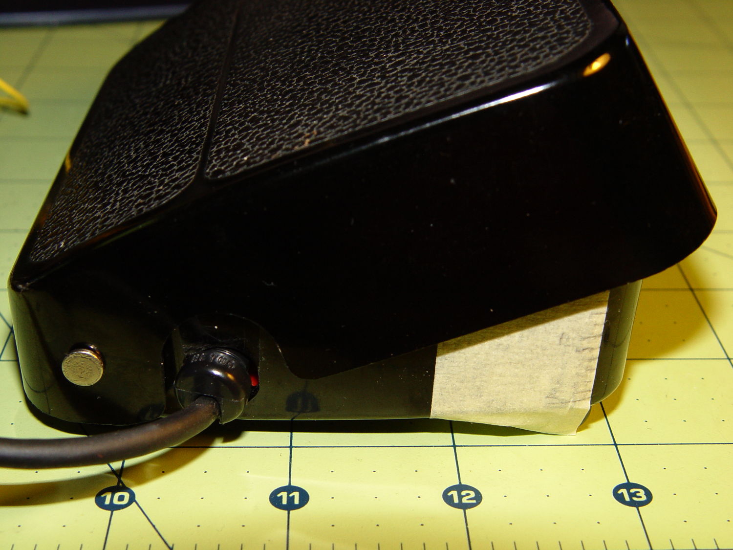
    The relocated platform height switch is about 4.5 mm higher than the nozzle, so:

    • Jog the nozzle off the platform to the right
    • Home the Z axis
    • Define that position as Z=-6: G92 Z-6
    • Move to Z=0: G0 Z0
    • Jog around measuring the height of the nozzle above the platform
    • Adjust screws to reduce variation
    • Change Z offset in startup G-Code
    • Run off a few test patterns to get the platform heated
    • Measure actual thickness
    • Change Z offset to get the right answer
    • Done!

    This progression of cold measurements, read top-to-bottom, left column first, shows the observed nozzle height above the platform around the edges and at the center:

    M2 Platform Leveling Progression - 2014-06-30
    M2 Platform Leveling Progression – 2014-06-30

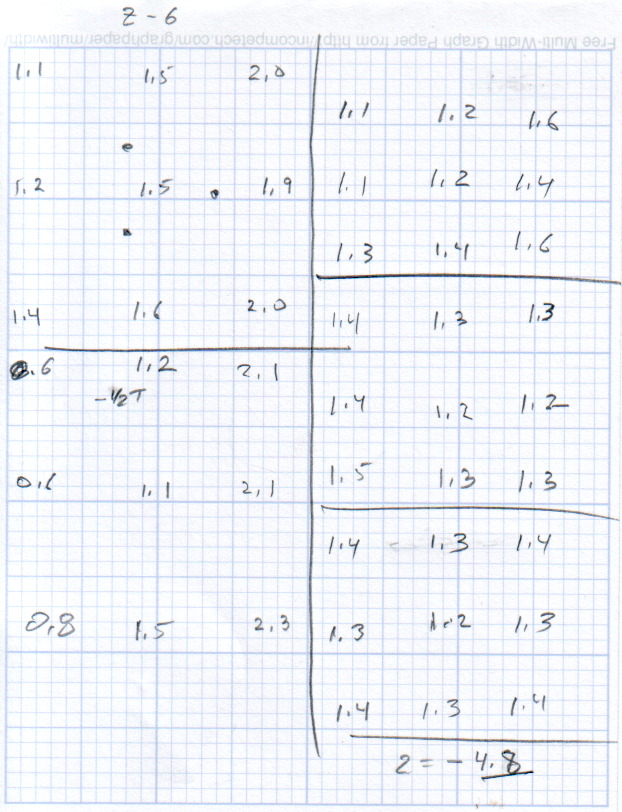
    The final measurements seem to indicate the glass plate is 0.2 mm convex in the center, but I wouldn’t trust the measurements to that level of accuracy. It’s probably bowed upward, but it’s certainly close enough.

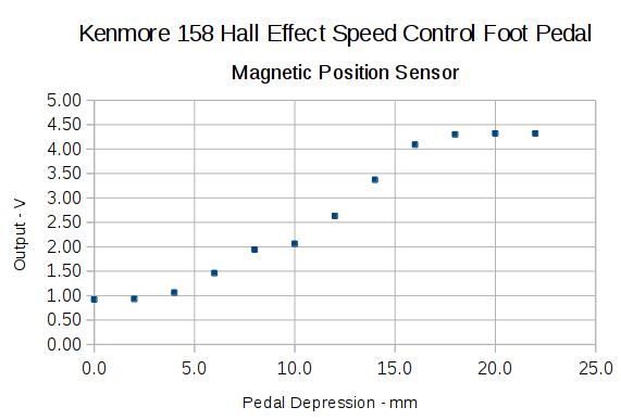
    The cold measurements suggest that the Z offset should be -4.80 mm, but the measurements on the hot platform with actual extrusion threads showed that -4.50 mm produced the correct thicknesses.

    It’s not clear automating the movements would produce better or faster results than just manually jogging the nozzle around the platform, particularly since it happens only every few months.

    This would be easier with the Z offset stored in the EEPROM and some modified startup G-Code to retrieve it.

  • Kenmore 158: Hall Effect Speed Control Output vs. Pedal Depression

    For lack of anything smarter, I marked the Kenmore 158 pedal’s range of motion in 2 mm increments, starting at the top:

    Kenmore 158 foot pedal - motion calibration
    Kenmore 158 foot pedal – motion calibration

    With the Hall effect sensor connected to a +5 V supply, the output looks like this:

    Hall sensor output vs pedal depression
    Hall sensor output vs pedal depression

    The point at 10 mm looks a bit out of place; other than that, the curve is about what you’d expect. The sensor saturates at about 0.84 V and 4.4 V, more or less, so you’re seeing the bias magnet on the low end and the main magnet on the high end.

    Obviously, you shouldn’t take these measurements too seriously, but they’re in the right ballpark.

    The pivot pin is 75 mm from the base of that line, so the subtended angle is more-or-less 16° = arctan(22/75), which is small enough that plotting the results as a function of the pedal angle doesn’t look any different.

    Although you could linearize that, I think the curve has the right shape for a foot pedal speed control: it starts slowly and tapers off smoothly at the high end.

    I think I could add a few more millimeters of magnet travel, but this will certainly suffice to get the crash test dummy running.


  • Kenmore 158: Motor Speed vs. DC Voltage

    Stuffing the AC motor back into the Kenmore Model 158 crash test dummy sewing machine, tightening the belts, powering it from the bench supply, and recording speed vs. voltage produces this interesting graph:

    Kenmore Model 158 AC Motor on DC - Loaded and Unloaded RPM vs Voltage
    Kenmore Model 158 AC Motor on DC – Loaded and Unloaded RPM vs Voltage

    The blue curve comes from the unloaded motor sitting bare on the bench. The red curve represents a more useful situation, with the motor driving the sewing machine’s main shaft, moving the needle carrier, spinning the bobbin housing, rotating a bunch of cams, and shoving the cranks. I expect the load would be higher while it’s actually punching thread into fabric / zigzagging / whatever, but probably less than a factor of two.

    The sewing machine’s top speed is around 8500 rpm, useful only for bobbin loading. Feeding that speed into the linear fit equation and turning the crank backwards says the motor would run from (wait for it) 99.5 V. The motor’s rating is 110 to 120 VAC, so it’s within 10%; that’s ignoring the whole AC vs. DC discussion and my relatively imprecise measurements.

    The motor draws about 300 mA unloaded and 500 mA loaded; those values remain essentially constant at all speeds. The loaded current increases by about 10% over the speed range, likely due to increasing mechanical load / windage losses inside the sewing machine.

    The locked rotor current is 880 mA at 40 and 45 V, rising to 1 A at 50 V.

    The bench supply has an adjustable current limit that steps in 30 mA increments. Starting with the supply in constant voltage mode, reducing the current by 30 mA from the free running value brings the motor to a gradual stop. As with all motors, the output torque comes from the winding current, but in a (series-wound) universal motor the same current energizes both the rotor and the stator windings: there’s a square-law positive feedback loop ending in a high current stall or a low current runaway.

    The usual triac speed control will not be useful in this situation, because it will generate an unacceptable level of audible noise.

    Closing the feedback loop through the operator’s foot on the pedal works surprisingly well, due to the relatively slow motor response. Duplicating that with, oh, say, an Arduino might require a bit more than just a PID loop.


  • Kenmore 158: Stepper Motor Max Speeds

    Having a NEMA 23 stepper fit almost exactly into the spot vacated by the sewing machine’s AC motor was too good to pass up:

    Kenmore 158 - NEMA 23 stepper - on adapter
    Kenmore 158 – NEMA 23 stepper – on adapter

    So I wired a power supply to an M542 stepper driver brick, connected the pulse output of a function generator to the brick’s STEP inputs, swapped motor leads until it turned the proper direction (CCW as seen from the shaft end), and turned the function generator knob:

    Kenmore 158 - NEMA 23 stepper test
    Kenmore 158 – NEMA 23 stepper test

    The object was to find the step frequency where the motor stalls, for various winding currents and supply voltages. The motor won’t have enough torque to actually stitch anything near the dropout speed, but this will give an indication of what’s possible.

    With a 24 V DC supply and 1/8 microstepping (40 k step/s = 1470 RPM):

    • 1.00 A = 11 k step/s
    • 1.91 A = 44 k/s
    • 2.37 A = 66 k/s
    • 3.31 A = 15 k/s

    With a 36 V DC supply and 1/8 microstepping:

    • 1.91 A = 70 k/s
    • 3.31 A = 90 k/s

    With a 36 V DC supply and 1/4 microstepping (40 k step/s = 2900 RPM):

    • 1.91 A = 34 k/s
    • 2.37 A = 47 k/s
    • 2.84 A = 47 k/s
    • 3.31 A = 48 k/s

    The motor runs faster with a higher voltage supply, which is no surprise: V = L di/dt. A higher voltage across the winding drives a faster current change, so each step can be faster.

    The top speed is about 3500 RPM; just under that speed, the motor stalls at the slightest touch. That’s less than half the AC motor’s top speed under a similarly light load and the AC motor still has plenty of torque to spare.

    90 k step/s at 1/8 microstepping = 11 k full step/s = crazy fast. Crosscheck: 48 k step/s at 1/4 microstepping = 12 k full step/s. The usual dropout speed for NEMA 23 steppers seems to be well under 10 k full step/s, but I don’t have a datasheet for these motors and, in any event, the sewing machine shaft provides enough momentum to keep the motor cruising along.

    One thing I didn’t expect: the stepper excites howling mechanical resonances throughout its entire speed range, because the adapter plate mounts firmly to the cast aluminum frame with absolutely no damping anywhere. Mary ventured into the Basement Laboratory to find out what I was doing, having heard the howls upstairs across the house.

    She can also hear near-ultrasonic stepper current chopper subharmonics that lie far above my audible range, so even if the stepper could handle the speed and I could damp the mechanics, it’s a non-starter for this task.

    Given that the AC motor runs on DC, perhaps a brute-force MOSFET “resistive” control would suffice as a replacement for the carbon disk rheostat in the foot pedal. It’d take some serious heatsinking, but 100 V (or less?) at something under 1 A and intermittent duty doesn’t pose much of a problem for even cheap surplus MOSFETs these days.

    That would avoid all the electrical and acoustic noise associated with PWM speed control, which counts as a major win in this situation. Wrapping a speed control feedback loop around the motor should stiffen up its low end torque.

  • Monthly Science: Springtime Ground Temperatures

    The last month’s ground temperatures:

    Temperatures - Garden Patio Water
    Temperatures – Garden Patio Water

    The “Garden” trace comes from a waterproof Hobo datalogger buried a few inches underground, beneath a thick layer of chipped leaf mulch. The “Patio” trace comes from the center of the cramped space below the concrete patio, buried flush with the bare dirt floor. The “Water” trace is the temperature at the incoming water pipe from the town water main, which passes 150 feet under the front yard.

    Calculated eyeballometrically, the temperature rose 7 °F in about a month.

    The datalogger in the garden came from the “cold cellar” veggie storage buckets, so I don’t have a year-long record. On the other paw, it looks like the patio temperature will be a pretty good proxy for the minimum garden temperature.

    I hand-cleaned the Hobo CSV files and fed the results into a Gnuplot script that’s replete with the cruft of ages:

    #!/bin/sh
    #-- overhead
    export GDFONTPATH="/usr/share/fonts/truetype/"
    ofile=Temperatures.png
    echo Output file: ${ofile}
    #-- do it
    gnuplot << EOF
    #set term x11
    set term png font "arialbd.ttf" 18 size 950,600
    set output "${ofile}"
    set title "Ground Temperatures"
    set key noautotitles right center
    unset mouse
    set bmargin 4
    set grid xtics ytics
    set timefmt "%m/%d/%Y %H:%M:%S"
    set xdata time
    set xlabel "Date"
    set format x "%Y-%m-%d"
    set xrange [:"07/15/2014"]
    set xtics font "arial,12"
    #set mxtics 2
    #set logscale y
    #set ytics nomirror autofreq
    set ylabel "Temperature - F"
    #set format y "%4.0f"
    #set yrange [30:90]
    #set mytics 2
    #set y2label "right side variable"
    #set y2tics nomirror autofreq 2
    #set format y2 "%3.0f"
    #set y2range [0:200]
    #set y2tics 32
    #set rmargin 9
    set datafile separator ","
    #set label 1 "Garden"     at "05/31/2014",25 left font "arialbd,10" tc lt 3
    #set arrow from 2.100,110 to 2.105,103 lt 1 lw 2 lc 0
    plot	\
        "Garden.csv" using 2:3 with lines lt 3 lw 1 title "Garden",\
        "Patio.csv"  using 2:3 with lines lt 2 lw 1 title "Patio",\
        "Water.csv"  using 2:5 with lines lt 4 lw 1 title "Water",\
    
    EOF
    
  • Silicone Caulk + Desiccant = Win!

    After doing the second batch of quilting pin caps, I dropped the newly opened silicone caulk tube into a jar with some desiccant, which worked wonderfully well. Unlike the usual situation where the caulk under the cap hardens into a plug after a few weeks, the tube emerged in perfect condition. In fact, even the caulk in the middle of the conical nozzle was in good shape, with just a small cured plug on either end; it had been sitting inside a cloth wrap with no sealing at all.

    Here’s what it looked like after finishing the last of the most recent caps:

    Silicone caulk tube with silica gel
    Silicone caulk tube with silica gel

    The indicator card says the humidity remains under 10%, low enough to keep the caulk happy and uncured. Well worth the nuisance of having a big jar on the top shelf instead of a little tube next to the epoxy.

    Although I thought the desiccant was silica gel, it’s most likely one of the clay or calcium desiccants.

  • Kenmore 158: AC Motor Running on DC!

    The sewing machine had a three-contact plug / terminal block that joins all the wiring:

    Kenmore 158 - terminal block
    Kenmore 158 – terminal block

    For completeness, the matching socket (not shown) joins two cords:

    • AC line cord (two wire, not polarized, no ground)
    • Foot pedal

    Extract the motor wiring from that block and connect it to a 50 V / 3 A bench supply, with the positive lead to the marked wire conductor:

    Kenmore 158 AC motor - DC power
    Kenmore 158 AC motor – DC power

    Cranking the voltage upward from zero:

    Kenmore Model 158 AC Motor on DC - RPM vs V
    Kenmore Model 158 AC Motor on DC – RPM vs V

    So that’s about 200 RPM/V, offset by 2800 RPM. Totally unloaded, of course.

    The original data:

    DC V DC A RPM Notes
    15 0.29 690 Barely turning
    20 0.28 1380 Finger-stoppable
    25 0.29 2350
    30 0.29 3450
    35 0.30 4450
    40 0.29 5740
    45 0.29 6780 Still finger-holdable at start
    50 0.29 8000

    I can hold the shaft stopped between my fingers up through 45 V, with 0.54 A locked-rotor current at 25 V. The motor doesn’t have a lot of torque, although it’s operating at less than half the normal RMS voltage.

    I should take those numbers with the motor driving the sewing machine to get an idea of the actual current under a more-or-less normal load.

    Reversing the power supply leads shows that the motor rotates only counterclockwise, which is exactly what you’d expect: both polarities of the normal AC sine wave must turn the motor in the same direction.