Ed Nisley's Blog: Shop notes, electronics, firmware, machinery, 3D printing, laser cuttery, and curiosities. Contents: 100% human thinking, 0% AI slop.
Category: Science
If you measure something often enough, it becomes science
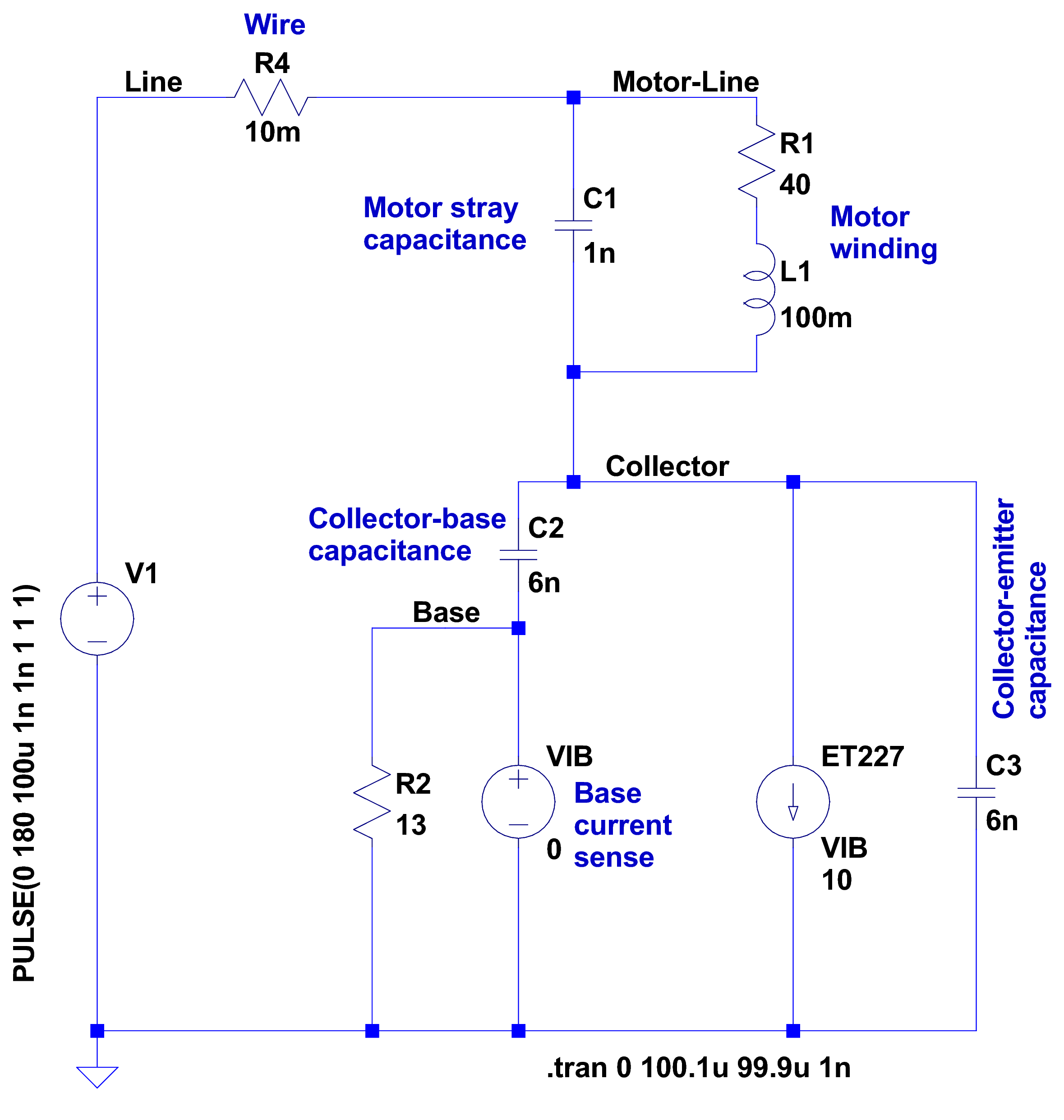
After having blown two ET227 transistors, I fiddled with some SPICE models to explore the ahem problem space. This seems to be the simplest model with all the relevant details:
Motor Transient – no NTC – schematic
A step change in the voltage source simulates the relay clicking closed with the AC line at a peak. R4 might resemble the total wiring resistance, but is more of a placeholder.
I measured 1 nF from each motor wire to the motor shell, so I assume a similar value from wire to wire across the winding. I can’t measure that, because, as far as my capacitance meters are concerned, the 40 Ω motor winding looks exactly like a resistor. R1 and L1 model the winding / commutator, but on the time scale we’re interested in, that branch remains an open circuit.
There’s no transistor model even faintly resembling a hulking ET227, so a current controlled current source must suffice. The 0 V VIB “source” in the base lead measures the base current for the CCCS labeled ET227, which applies a gain of 10 to that value and pulls that current from the collector node. R2 is the internal base-emitter resistor built into the ET227.
C2 is the 6 nF (!) collector-base capacitance I measured at zero DC bias on a good ET227. That’s much more than you’ll find on any normal transistor and I’m basically assuming it’s vaguely related to the Miller capacitance of small-signal fame. C3 is a similar collector-emitter capacitor; I can’t tell what’s going on under the hood without a whole lot of measurement equipment I don’t have.
So, without further ado:
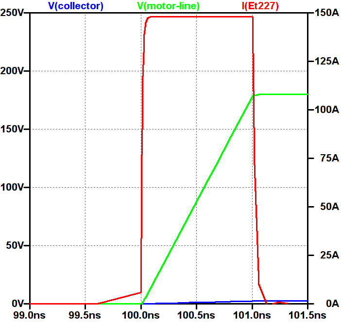
Simple Transient Model – current pulse
Whenever you see a simulation result like that, grab your hat in both hands and hunker down; the breeze from the handwaving will blow you right off your seat.
The key unknown: the rise time of the voltage step as the relay contacts snap closed. Old-school mercury-wetted relay contacts have rise times in the low tens of picoseconds. Figuring dry high-power contacts might be 100 times slower gives a 1 ns rise time that I can’t defend very strongly; it seems to be in the right ballpark. The green trace shows the input voltage ramping to 180 V in 1 ns, which is pretty much an irresistible force.
The motor shunt capacitance forms a voltage divider with the parallel base and collector capacitors, so the collector voltage shouldn’t exceed 180 * (1/(1+3)) = 45 V. In fact, the blue trace shows the collector voltage remains very low, on the order of 10 V, during the whole pulse.
The red trace shows the collector current hitting 150 A during the entire input ramp, which is exactly what you’d expect from the basic capacitor equation: I = C dv/dt. The current depends entirely on the absurdly fast 180 V / 1 ns rate: if the relay rise time is actually smaller, the current gets absurdly higher.
The ET227 datasheet remains mute on things like junction capacitance, damage done by nanosecond-scale high-current pulses, and the like.
Absolutely none of those numbers have even one significant figure of accuracy, but I think the overall conclusion that I’m blowing junctions based on transient startup currents through the collector holds water.
Adding four of those NTC power thermistors seems in order. This picture also shows the snubber hanging from the back of the ET227, but I eventually took that off because the simulations show it’s not doing anything useful and it does resonate with the 120 Hz halfwave supply:
HV Interface – snubber and thermistors
The thermistors get comfortably warm after a few minutes and settle out around 1 Ω apiece. Adding 4 Ω to the simulation reduces the current to 30 A during a 1 ns ramp, which number obviously depends on all the assumptions mentioned above.
I’ve been running it like that for a few hours of start-stop operation and the ET227 lives on, so maybe I can declare victory.
Two mornings after a heavy, wet snowfall, the meltwater atop the concrete patio puckered up into ice crystals:
Ice crystals on patio
It seems the liquid water collects into the crystals as they freeze, leaving the concrete between the ice patches nearly dry. They seem surprisingly linear, with only a few hexagonal flourishes here and there.
This Cooper’s Hawk (*) kept an eye on us as we walked down the driveway:
Coopers Hawk – keeping an eye on us
We obviously pose no threat, so he let us pass unmolested.
I think the real reason had more to do with the dark brown-red stains on his (?) claws: that hawk just ate a fine meal and wanted time for quiet digestion and contemplation…
Hand-held Canon SX230HS, plenty of zoom, lots of purple fringing, and a cooperative bird.
(*) A juvenile, obviously, who could be either a Cooper’s or a Sharp-Shinned Hawk.
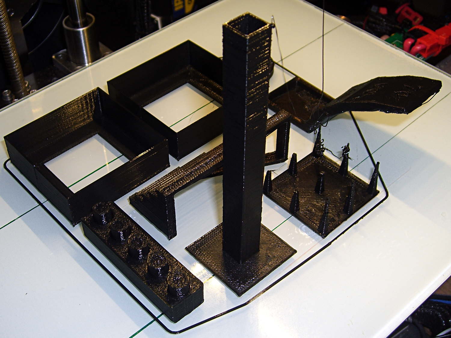
Just for completeness, here’s how the MAKE Magazine 2015 Test Objects came out on my somewhat modified MakerGear M2. I ignored the instructions, lumped all the models together, sliced ’em with my ordinary Slic3r settings, and printed the entire lot in one go:
MAKE Magazone 2015 Test Objects – on platform
Some details…
There’s no point in showing the Dimension Accuracy Tower-of-Hanoi (hiding behind the smokestack), as it looks exactly like it should. The 20 mm diameter platter came out at 19.7 ± 0.05 mm in both X and Y, so that’s a score of 2 or 3. It’s exactly the same along both axes, both diagonals, and, in fact, all the way around, within ±0.07 mm tolerance. In fact, all the layers worked out about that way; it’s consistently a bit too small. That’s what I’d expect for an uncalibrated model.
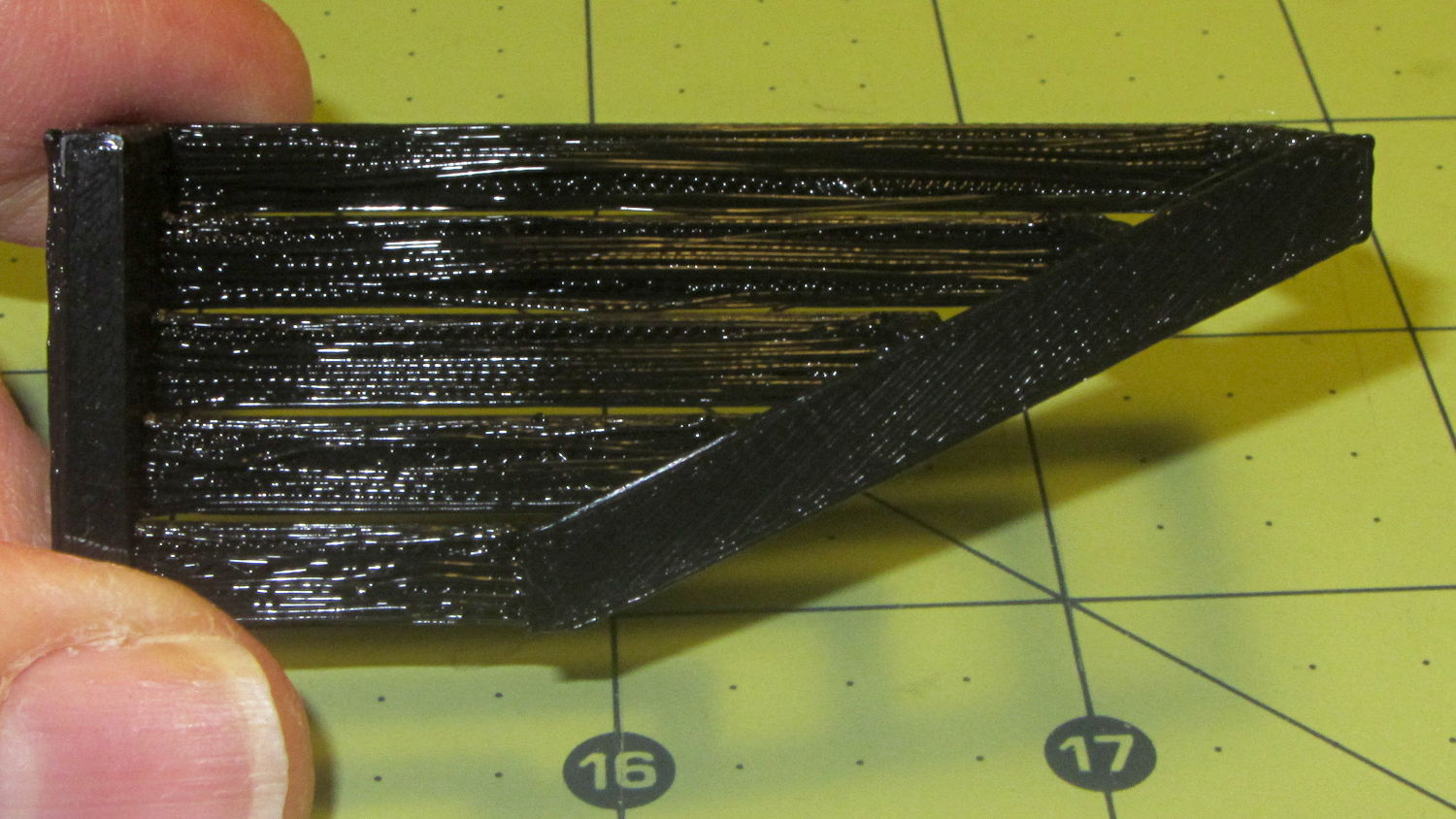
The Bridging Performance lattice gets a 5, with all the bars having dead-flat perimeters and no dropped infill. That would be a 1 if “dropped” should be “drooped”; I have no idea which is correct or exactly what they mean, but I have seen bridge threads drop off the sides, so I’ll assume it means what it says.
The front view shows the first bridging layer getting droopy under the longer bars, as you’d expect:
Bridging – front
All those drooping threads remain above the 2 mm tolerance, assuming that’s what they intended.
The bottom view shows the loose strands below the bars:
Bridging – bottom
The Overhang Performance arch gets a 5, because the top surface finish remains pretty much the same from 30° through 70° overhang:
Overhang – upper
Underneath, things look weirder:
Overhang – lower
I think the oddness on the left (the underside of the 30° section) is due to interference from the Fine Positive Space Features spire array; the nozzle came directly from there. The 70° overhang looks ugly, but I wouldn’t have imagined that would work at all, let alone as well as it did.
The Negative Space Tolerance block weighs in at 2, as the pins with 0.6 and 0.5 mm clearance pushed out with finger pressure. The 0.3 and 0.4 mm clearance pins have air nearly all the way around, but would require a sharp rap from a mallet. The 0.2 mm pin remains firmly stuck:
Negative Space Tolerance
I don’t know how to judge the Fine Positive Space Features bed-o’-nails:
Fine Positive
I think it’s either a 2 or a 3, but opinions will certainly differ. Hot off the platform, five of the nine spires completed successfully. Three other got almost done, but broke off in handling. The collection of drool on the left-middle spire seems to be from the uncompleted spires in the foreground; I think there just wasn’t enough adhesion to hold them together. The perimeters ran at 50 mm/s and the infill at 150 mm/s, because it’s printed with everything else, so it wasn’t done with the delicacy it would get in isolation.
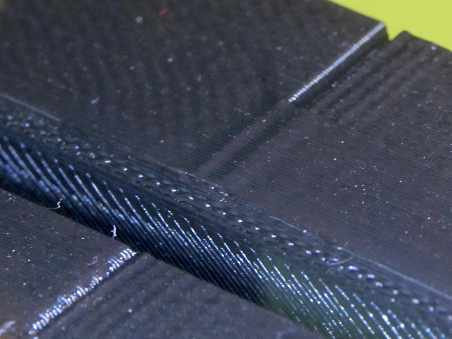
Both Mechanical Resonance in XY boxes look fine to me:
XY Resonance – notch
The ripples are visible, but barely perceptible to the thumbnail. The Rules call for 0 or 2, I’d give it a 1: if those ripples pose a problem, then sheesh you’re using the wrong process.
Also, the perimeters ran at 50 mm/s perimeter and the thick walls got 150 mm/s infill.
A corner of the single-wall box looks about the same as the corresponding point on the 1 mm box (which isn’t shown):
XY Resonance – corner
I think the Mechanical Resonance in Z smokestack gets a 1 (the Rules allow either 0 or 2); I stopped it after 100 mm, because bedtime. The bottom section shows the influence of all the other stuff going on around it:
Z Resonance – lower
That’s not a missed step over there on the far left: it lines up with the bottom bar of the adjacent Bridging Performance lattice. The next glitch lines up with the top of the Negative Space block. And so forth and so on.
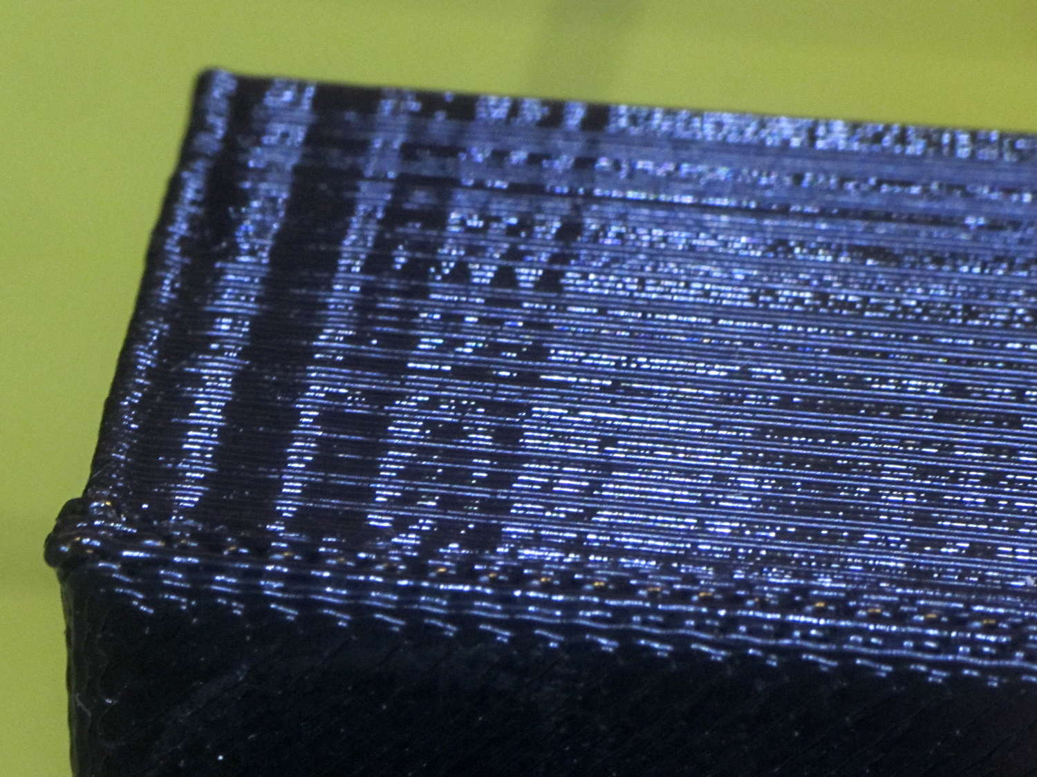
The top, done all by itself at 11 mm/s, shows some misalignment:
Z Resonance – upper
Each layer took 15 seconds, so I suspect it’d look better with more cooling.
So, using ordinary default settings for everything and with all the handwaving in mind, I’ll call the total score 19-ish of a possible 29. The M2 would definitely do better on individual objects sliced with carefully hand-tuned parameters after considerable iteration; this is its ordinary, day-in-and-day-out performance on crazy models that I’d never attempt without tweaking.
The score would be much much much higher if I judged it with criteria similar to what I see applied to some of the Thingiverse groupings.
The M2 works well for me, anyhow.
For reference, here’s the current Slic3r configuration:
# generated by Slic3r 1.2.1 on Sun Dec 7 12:19:19 2014
avoid_crossing_perimeters = 0
bed_shape = -100x-125,100x-125,100x125,-100x125
bed_temperature = 70
bottom_solid_layers = 3
bridge_acceleration = 0
bridge_fan_speed = 100
bridge_flow_ratio = 1
bridge_speed = 150
brim_width = 0
complete_objects = 0
cooling = 1
default_acceleration = 0
disable_fan_first_layers = 1
dont_support_bridges = 1
duplicate_distance = 6
end_gcode = ;-- Slic3r End G-Code for M2 starts --\n; Ed Nisley KE4NZU - 15 November 2013\nM104 S0 ; drop extruder temperature\nM140 S0 ; drop bed temperature\nM106 S0 ; bed fan off\nG1 Z160 F2000 ; lower bed\nG1 X130 Y125 F30000 ; nozzle to right, bed front\nM84 ; disable motors\n;-- Slic3r End G-Code ends --
external_perimeter_extrusion_width = 0
external_perimeter_speed = 50
external_perimeters_first = 0
extra_perimeters = 1
extruder_clearance_height = 25
extruder_clearance_radius = 15
extruder_offset = 0x0
extrusion_axis = E
extrusion_multiplier = 1.07
extrusion_width = 0.4
fan_always_on = 0
fan_below_layer_time = 30
filament_diameter = 1.72
fill_angle = 45
fill_density = 20%
fill_pattern = 3dhoneycomb
first_layer_acceleration = 0
first_layer_bed_temperature = 70
first_layer_extrusion_width = 0.4
first_layer_height = 100%
first_layer_speed = 25
first_layer_temperature = 175
gap_fill_speed = 50
gcode_arcs = 0
gcode_comments = 0
gcode_flavor = reprap
infill_acceleration = 0
infill_every_layers = 2
infill_extruder = 1
infill_extrusion_width = 0
infill_first = 1
infill_only_where_needed = 0
infill_speed = 150
interface_shells = 0
layer_gcode =
layer_height = 0.2
max_fan_speed = 100
min_fan_speed = 75
min_print_speed = 4
min_skirt_length = 15
notes =
nozzle_diameter = 0.35
only_retract_when_crossing_perimeters = 1
ooze_prevention = 0
output_filename_format = [input_filename_base].gcode
overhangs = 1
perimeter_acceleration = 0
perimeter_extruder = 1
perimeter_extrusion_width = 0.4
perimeter_speed = 150
perimeters = 2
post_process =
raft_layers = 0
resolution = 0.01
retract_before_travel = 1
retract_layer_change = 0
retract_length = 1
retract_length_toolchange = 5
retract_lift = 0
retract_restart_extra = 0
retract_restart_extra_toolchange = 0
retract_speed = 60
seam_position = nearest
skirt_distance = 3
skirt_height = 1
skirts = 3
slowdown_below_layer_time = 10
small_perimeter_speed = 50
solid_fill_pattern = rectilinear
solid_infill_below_area = 5
solid_infill_every_layers = 0
solid_infill_extrusion_width = 0
solid_infill_speed = 150
spiral_vase = 0
standby_temperature_delta = -5
start_gcode = ;-- Slic3r Start G-Code for M2 starts --\n; Ed Nisley KE4NZU - 15 Nov 2013\n; 28 Feb 2014 - 6 Mar 2014 - tweak Z offset June July 2014\n; Z-min switch at platform, must move nozzle to X=130 to clear\nM140 S[first_layer_bed_temperature] ; start bed heating\nG90 ; absolute coordinates\nG21 ; millimeters\nM83 ; relative extrusion distance\nG92 Z0 ; set Z to zero, wherever it might be now\nG1 Z10 F1000 ; move platform downward to clear nozzle; may crash at bottom\nG28 Y0 ; home Y to be sure of clearing probe point\nG92 Y-127 ; set origin so 0 = center of plate\nG28 X0 ; home X\nG92 X-95 ; set origin so 0 = center of plate\nG1 X130 Y0 F30000 ; move off platform to right side, center Y\nG28 Z0 ; home Z with switch near center of platform\nG92 Z-4.65 ; set origin to measured z offset\nG0 Z2.0 ; get air under switch\nG0 Y-127 F10000 ; set up for priming, zig around corner\nG0 X0 ; center X\nM109 S[first_layer_temperature] ; set extruder temperature and wait\nM190 S[first_layer_bed_temperature] ; wait for bed to finish heating\nG1 Z0.0 F500 ; put extruder at plate \nG1 E30 F300 ; prime to get pressure, generate blob\nG1 Z5 F2000 ; rise above blob\nG1 X15 Y-125 F20000 ; jerk away from blob, move over surface\nG1 Z0.0 F1000 ; dab nozzle to attach outer snot to platform\nG4 P0.5 ; pause to attach\nG1 X35 F500 ; slowly smear snot to clear nozzle\nG1 Z1.0 F2000 ; clear bed for travel\n;-- Slic3r Start G-Code ends --
support_material = 0
support_material_angle = 0
support_material_enforce_layers = 0
support_material_extruder = 1
support_material_extrusion_width = 0
support_material_interface_extruder = 1
support_material_interface_layers = 3
support_material_interface_spacing = 0
support_material_interface_speed = 100%
support_material_pattern = pillars
support_material_spacing = 2.5
support_material_speed = 150
support_material_threshold = 0
temperature = 175
thin_walls = 1
threads = 2
toolchange_gcode =
top_infill_extrusion_width = 0
top_solid_infill_speed = 50
top_solid_layers = 3
travel_speed = 250
use_firmware_retraction = 0
use_relative_e_distances = 0
vibration_limit = 0
wipe = 0
xy_size_compensation = 0
z_offset = 0
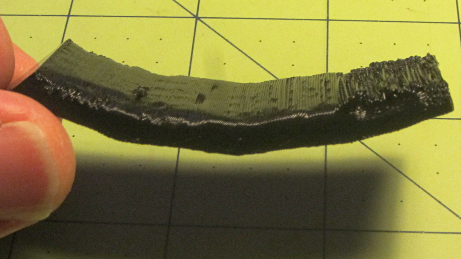
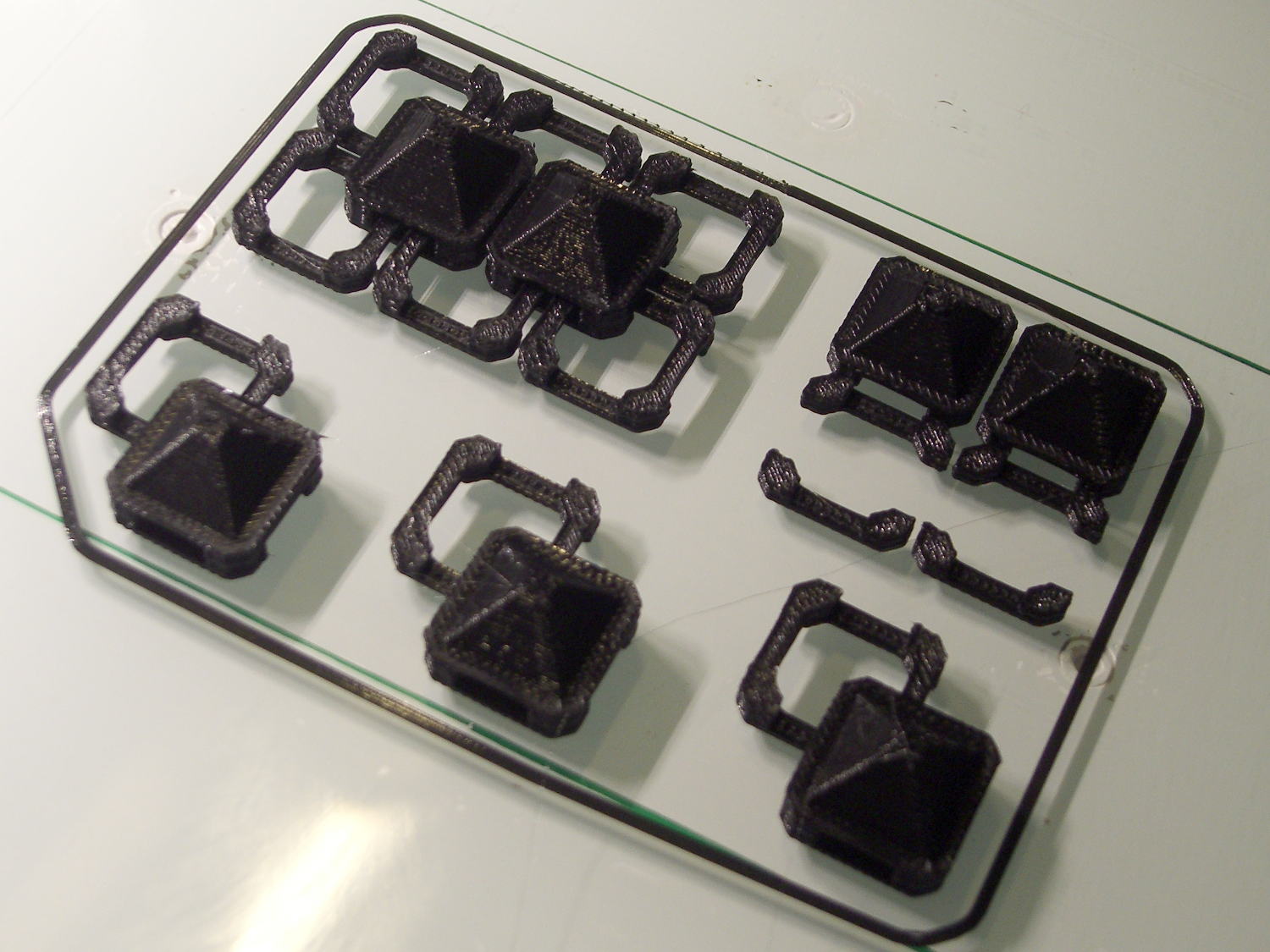
With about two meters of black PLA left on the spool, a pair of spare joiner links and a few tchotckes seemed in order:
Chain Mail Armor – spares and samples
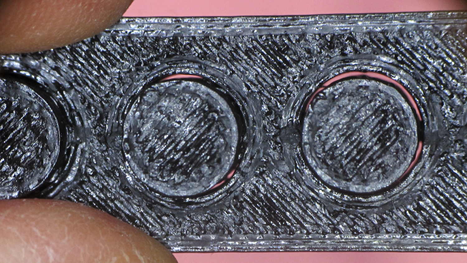
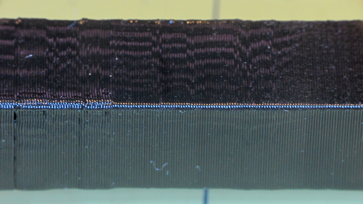
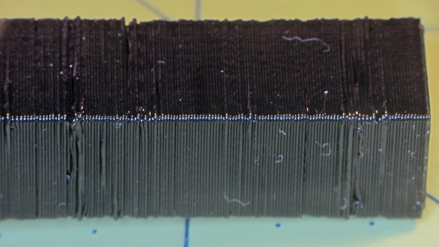
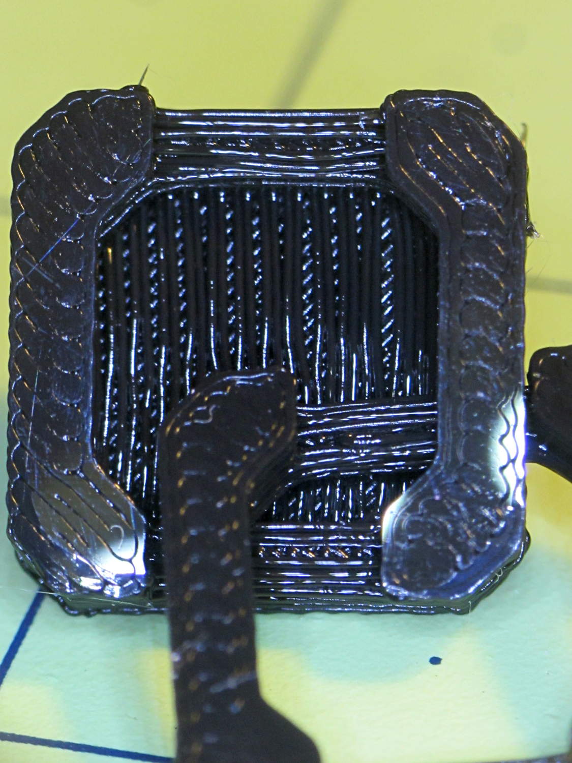
The underside of the samples shows the bridges between the pillars and the cap layer between the sides:
Chain Mail Armor – link bottom
The bridge strands start out droopy, then pull into a more-or-less straight thread as the plastic cools and shrinks. The next layer up looks much, much better.
I can spend a long time watching the nozzle stretch threads across the chasms, putting me in a definite Channel Zero state of mind…
A red-bellied woodpecker landed on the seed feeder, but the flapping tells you something’s not right:
Red-bellied woodpecker at feeder – closing
After the fluttering stopped, the seeds had vanished:
Red-bellied woodpecker at feeder – puzzled
According to our books, a red-bellied woodpecker weighed 72.5 g = 2.6 oz back in 1952. The feeder counterweight reads 3 oz and that’s confirmed by my pull scale. Perhaps woodpeckers suffer from the obesity epidemic, too?
The feeder closes with one cardinal (44 g) and two tufted titmouses (2 x 22 g), all of whom seem rather surprised at the situation.
It seems the batch of Energizer CR2032 lithium cells I bought a while ago reached the end of their shelf life:
Energizer CR2032 – short life
In point of fact, I replaced three CR2032 cells this month, all with anomalously short lives: one month counts as a complete failure. The Energizer date code YA isn’t helpful in determining when they were manufactured or what the shelf life might be.
Admittedly, I bought that batch in late 2009, so they might have used up most of their shelf life on somebody else’s shelf. There’s no way to know.
It’s not clear one can buy known-good cells from any supplier these days, as the counterfeiters evidently get genuine holograms from the same factory as the Brand Names.