Ed Nisley's Blog: Shop notes, electronics, firmware, machinery, 3D printing, laser cuttery, and curiosities. Contents: 100% human thinking, 0% AI slop.
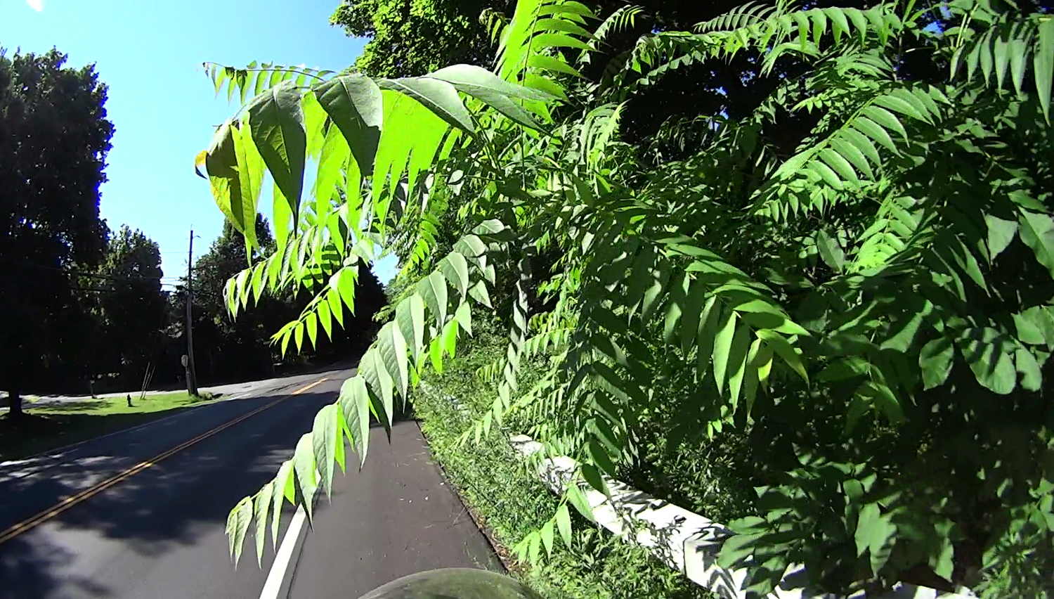
I’ve been carrying shears to deal with the most egregious offenses, because some sport inch-long thorns:
Rt 376 – SB at Walker – Thorns – 2017-07-09
Unlike the NYSDOT Wappingers (a.k.a. Dutchess South) Residency , their Poughkeepsie (a.k.a. Dutchess North) Residency has no compunction about defoliation around road signs:
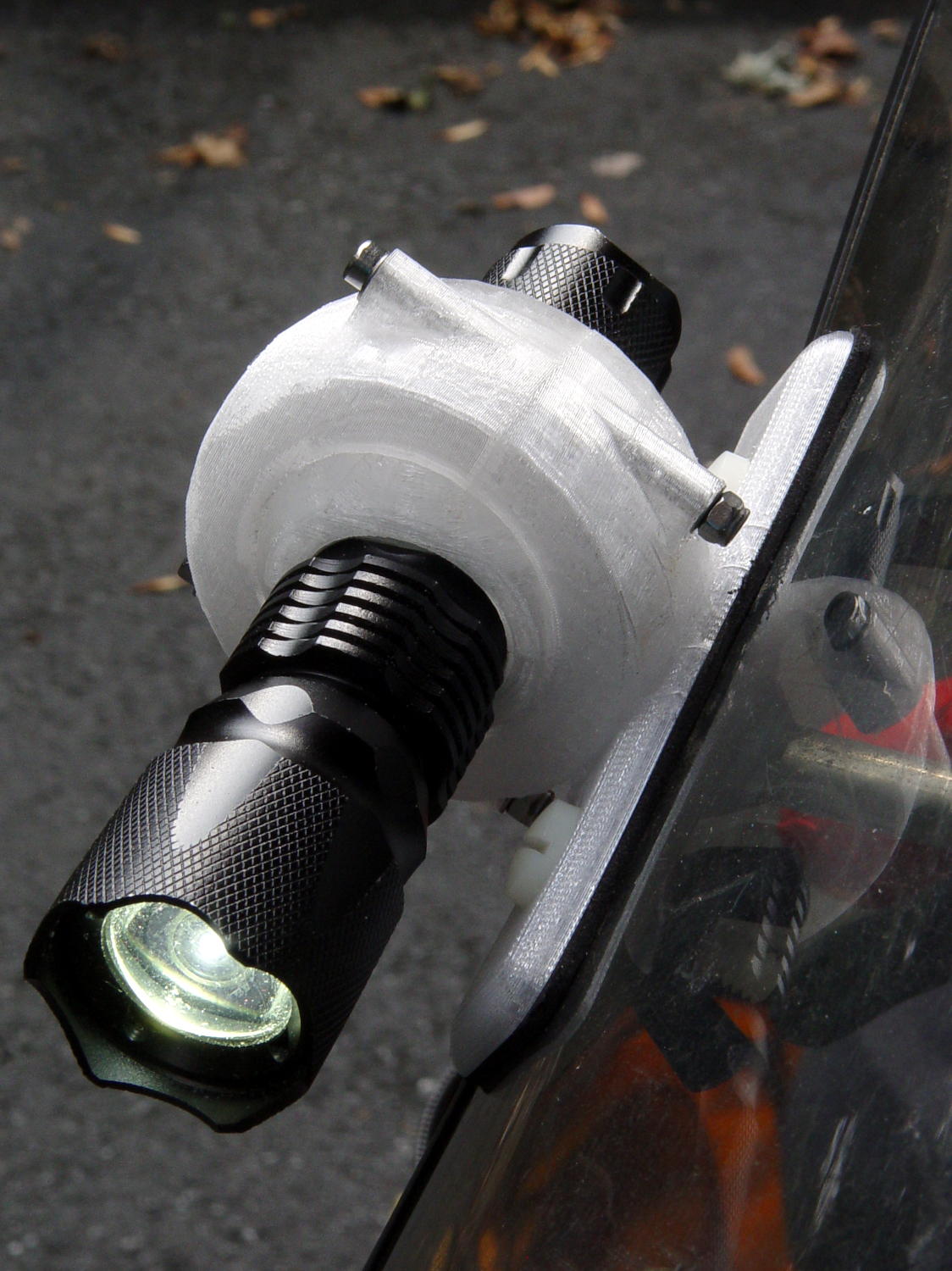
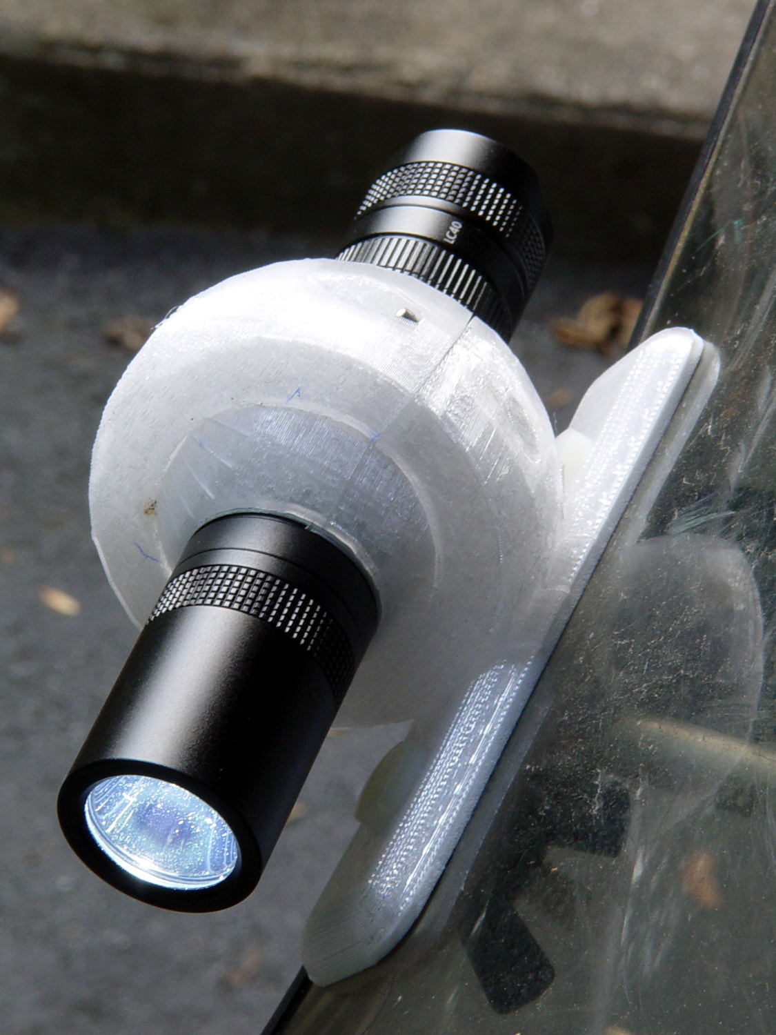
With the flashlight firmly clamped inside its ball, a surrounding clamp ring holds the ball on the mount:
Tour Easy – J5 Tactical V2 – front
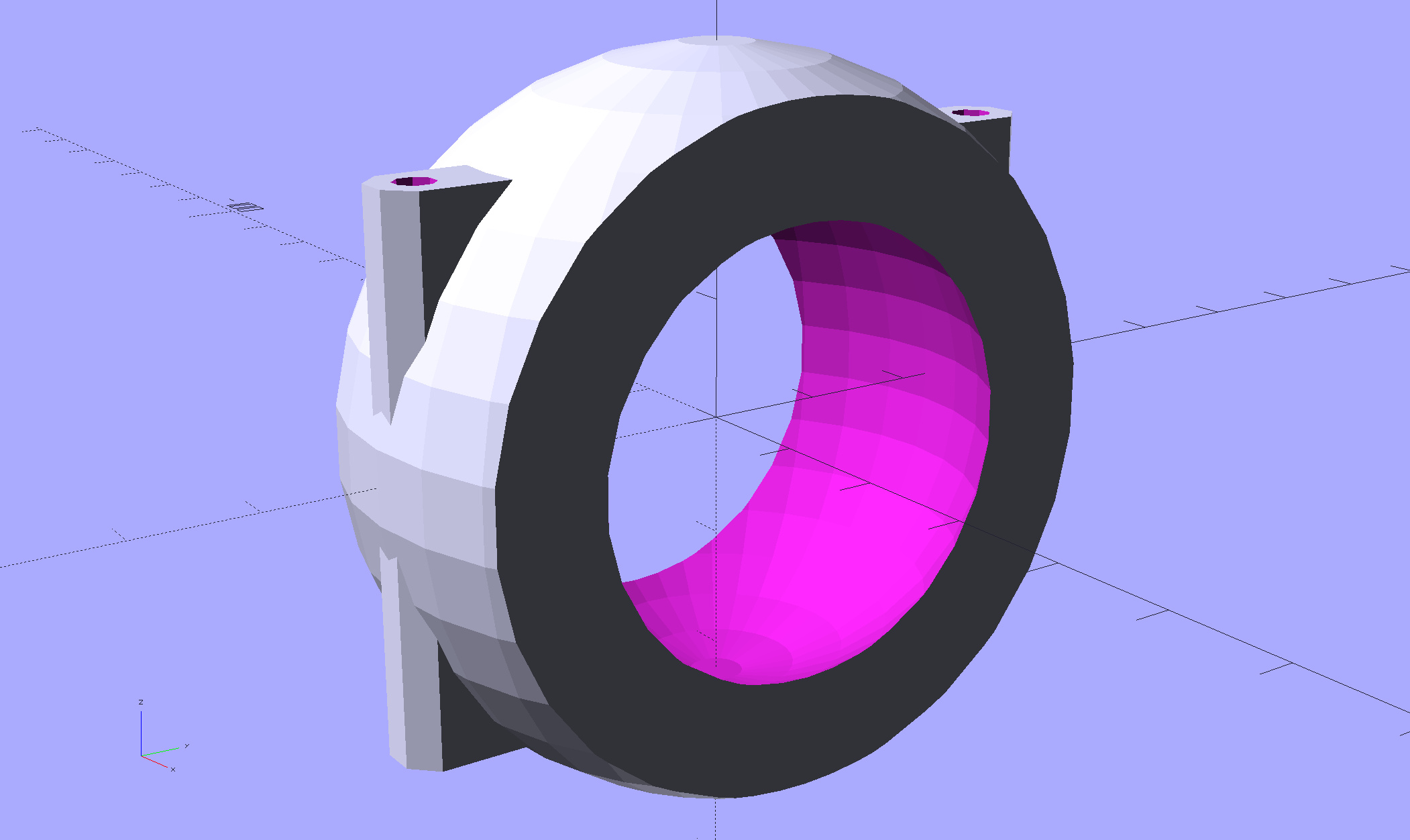
The solid model chops a sphere to a completely empirical 70% of the inner ball’s length (which, itself, may be truncated to fit the flashlight grip) and glues on a hull containing the M3x50 mm screws:
This file contains hidden or bidirectional Unicode text that may be interpreted or compiled differently than what appears below. To review, open the file in an editor that reveals hidden Unicode characters.
Learn more about bidirectional Unicode characters
The complete ring looks about like you’d expect, although it’s never built like this:
Fairing Flashlight Mount – Clamp – show view – solid model
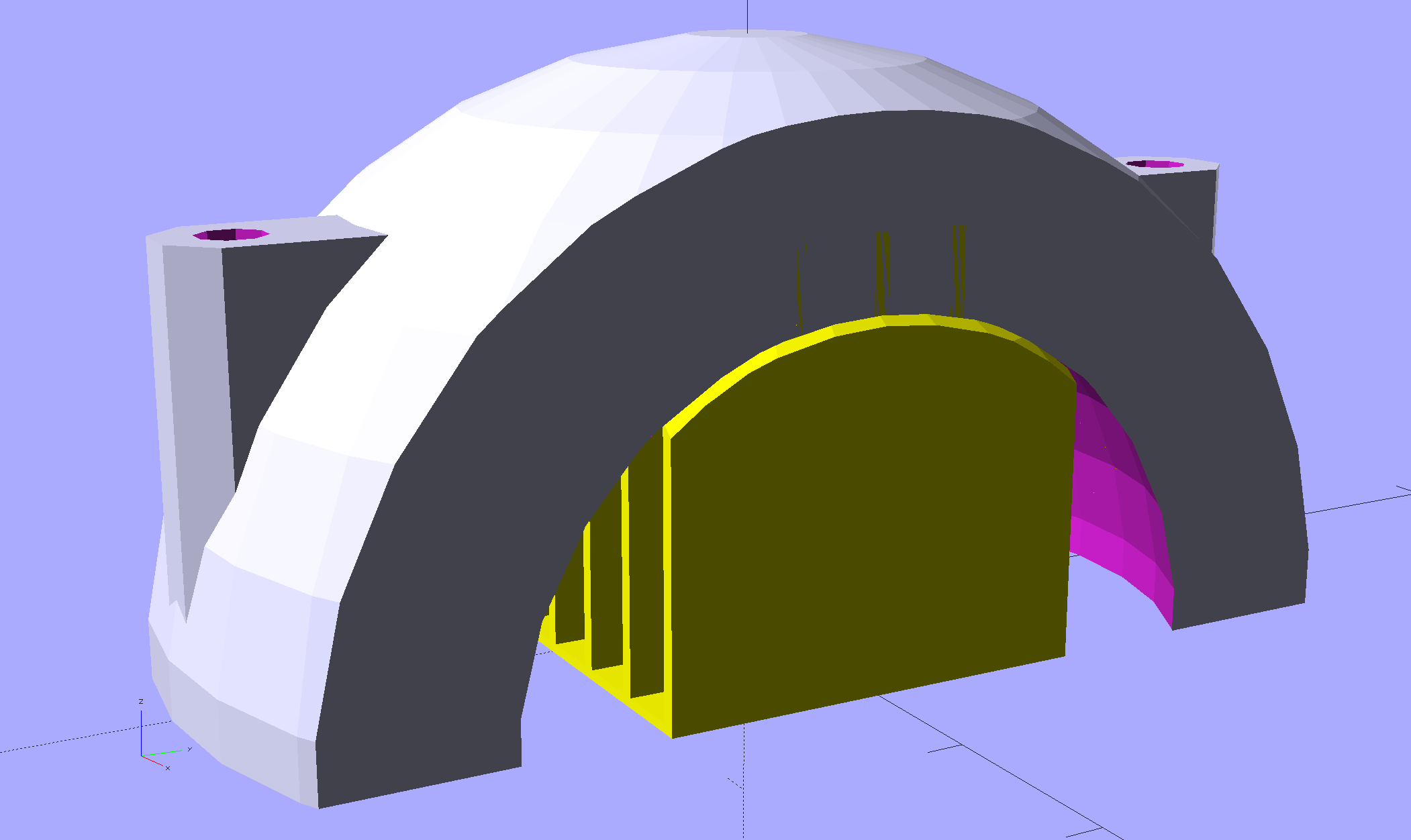
The top half builds as an arch on the platform:
Fairing Flashlight Mount – Clamp – build view – solid model
The uppermost layers on the inside of the arch have terrible overhang pulled upward by the cooling plastic, so the builtin support structure hold the layers downward. The preview shows they don’t quite touch, but in actual practice the support bonds to the arch and requires a bit of effort to crack off:
Fairing Flashlight Mount – support structures
The ones on the right come from my (failed) attempts to build the ball hemispheres in the obvious orientation. It’s worth noting that my built-in “support” both bonds to the part and breaks off in one piece, quite unlike the pitched battle required to separate Slic3r’s automatic support structures; I think that’s the difference between the minimum feasible and maximum possible support.
Anyhow, the inside of the arch requires only a bit of cleanup with a ball mill before it clamps firmly around the flashlight ball. In the normal orientation, the space over the missing ball cap snuggles into the cleaned-up part of the arch and there’s enough friction on the remaining ball to hold it in place. If it does joggle loose, a wrap of tape should provide enough griptivity.
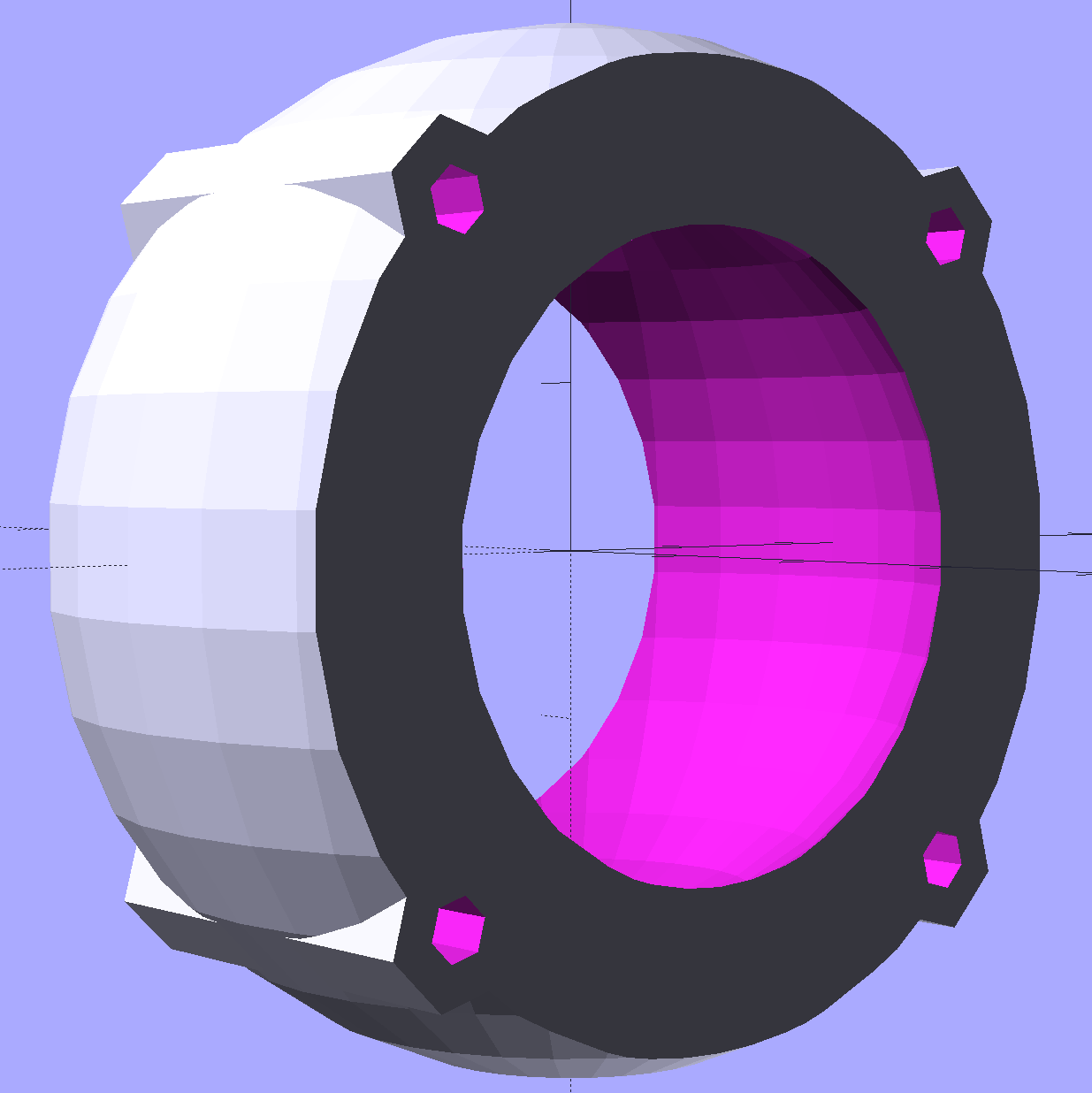
I started by assuming socket-head cap screws and brass inserts embedded in the clamp ring could provide enough force to hold everything together:
Fairing Flashlight Mount – Clamp – screw inserts – solid model
The head recesses into the top opening and the insert sits just below the split line on the XY plane. That turned out to be asking a lot from a pair of 3 mm knurled brass inserts, even with JB Weld in full effect, and I wasn’t at all confident they wouldn’t pop out under duress and fling the flashlight away.
Each screw now compresses the entire boss between a pair of washers and the nyloc nut won’t vibrate loose. The screws also serve to stiffen the clamp ring front-to-back, although I’m not convinced it needs any reinforcement.
I also considered splitting the ring parallel to the front, right down the middle, with screws extending through both halves:
Fairing Flashlight Mount – Clamp – Front Back split – solid model
It’d be trivially easy to build the front half face-down on the platform, but the rear would have only half the surface area bonded to the plate against the fairing, which seemed like a Bad Idea. Worse, I couldn’t figure out how to align the rear half on the plate with enough room for the nuts / inserts / whatever and alignment space around the front half.
A flashlight used as a daytime running light must point generally forward and an actual bike headlight must light up the road, so it must sit on an az-el mount. My old bike helmet mirror mount had actual vertical and horizontal joints:
Helmet mirror mount – El slide in place
Every doodle along those lines seemed too big, too fragile, too fiddly, or all at once.
Living here in the future, though, we can produce (crude) ball joints to order:
Flashlight Ball Mount
That’s an early version of the outer mount using threaded brass inserts.
The ball around the flashlight separates along the obvious plane of symmetry, with a 2 mm socket-head cap screw and brass insert on each side. I tried printing the hemispheres convex-side-up with hand-hewn support structures inside:
Flashlight Ball Mount – support structure – on platform
The huge overhanging sections parallel to the axis didn’t bond to the supports, curled upward, and began nudging the dangling Z-axis homing switch actuator. This wasn’t a completely wasted effort, though, as similar support structures came in handy for the outer clamp ring.
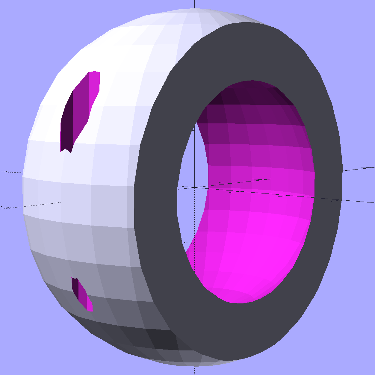
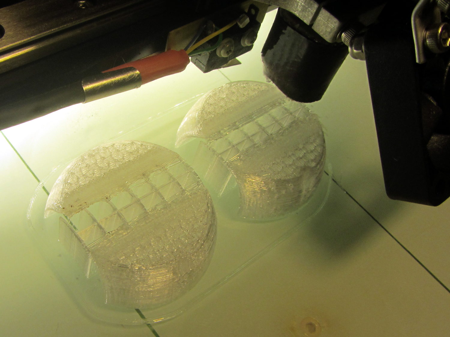
Flipping the hemispheres over so they printed U-channel upward didn’t work much better, even sitting on a flat section to eliminate the absurd part of the overhang. This view shows one hemisphere with the missing cap:
Fairing Flashlight Mount – Ball – solid model
Flipped over, the flat surface bonded perfectly to the platform, but the overhang still warped as the upper layers cooled and pulled the perimeter upward:
Flashlight Ball Mount – warped section
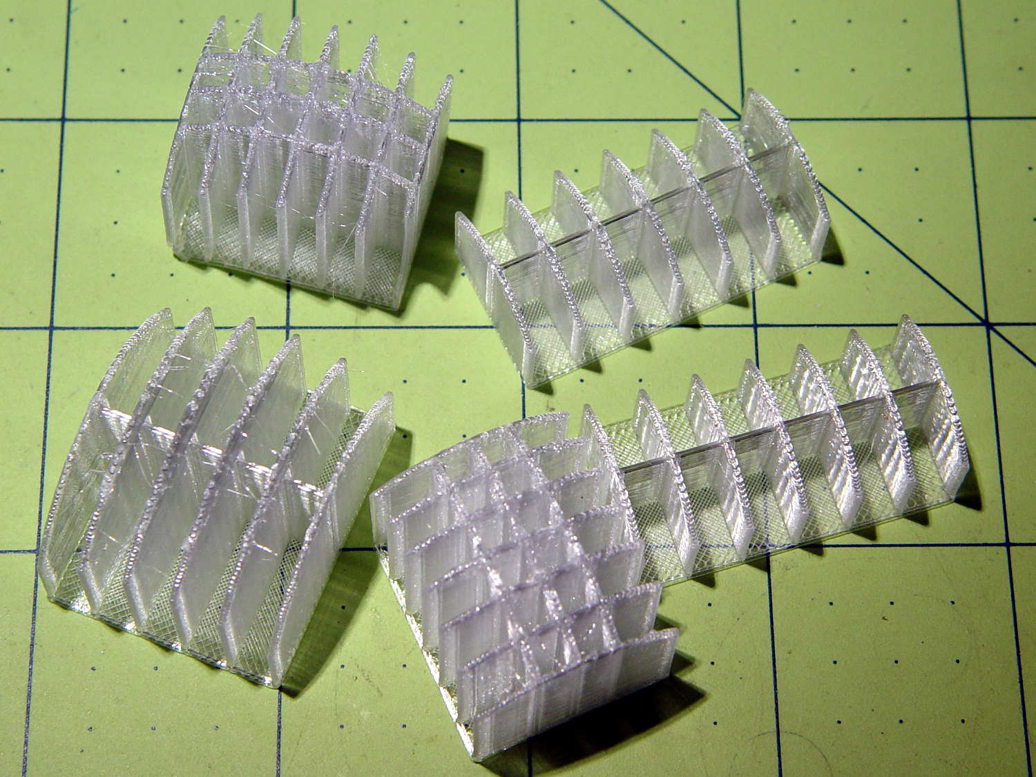
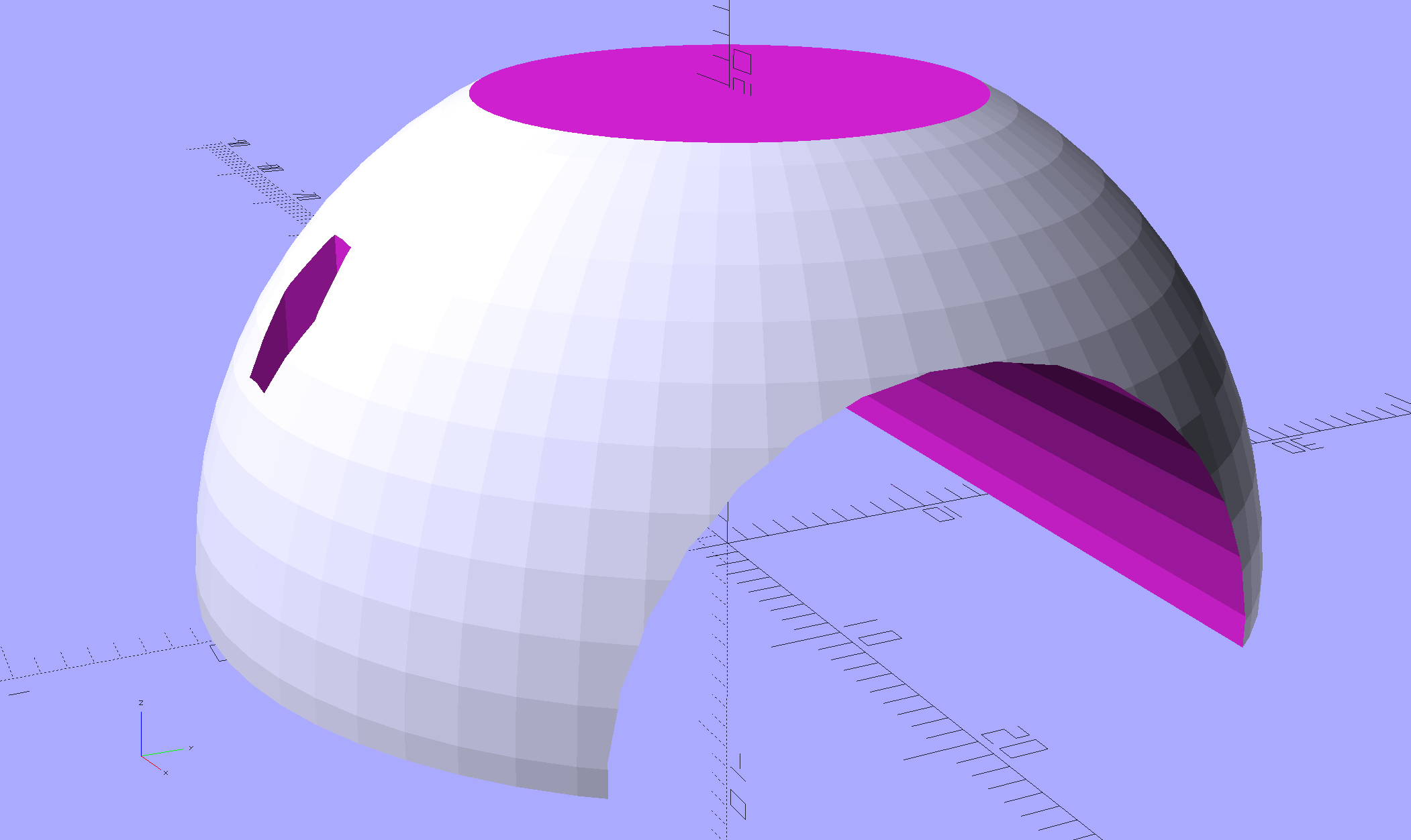
Because normal support structures don’t contact the outer surface, I added fins to the model to hold the perimeter (almost) flat until the outer walls became sufficiently vertical to stop warping:
Fairing Flashlight Mount – Ball – build view – solid model
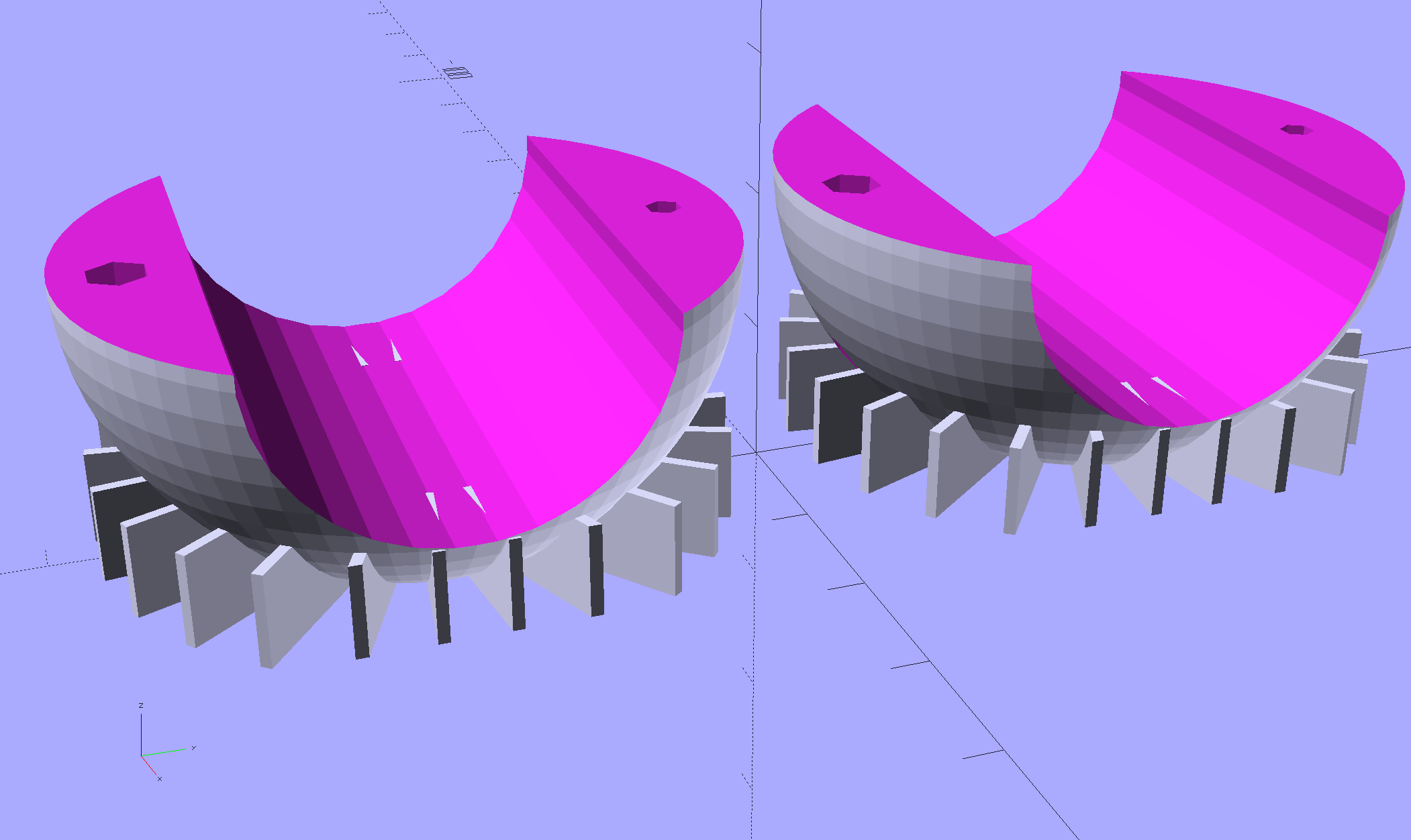
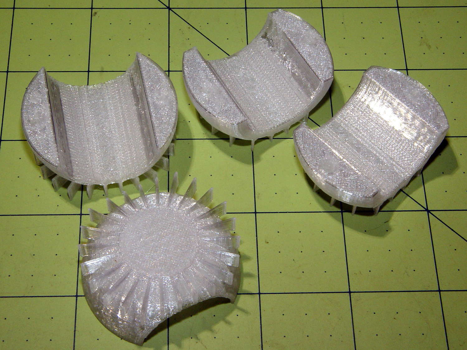
They’re fearsome hedgehogs in person:
Flashlight Ball Mount – flattening fins
The grip diameter determines the sphere diameter, as the sphere must have enough meat next to the grip to hold the screws and inserts. Rather than have the diameter different for every flashlight, I set it to the maximum of 45 mm or the actual diameter, which means all the flashlights in my collection have a common ball size. The hemispheres on the right have flattened ends to accommodate flashlight grips shorter than the sphere’s final diameter, achieved with a pair of intersection() operations lopping off the protruding bits:
This file contains hidden or bidirectional Unicode text that may be interpreted or compiled differently than what appears below. To review, open the file in an editor that reveals hidden Unicode characters.
Learn more about bidirectional Unicode characters
Because the fins extend from resolutely convex surfaces, I snipped them off with flush-cutting pliers, reamed out the holes, epoxied the inserts in place, assembled the ball, and introduced it to Mr Belt Sander.
Protip: don’t hold the ball with your finger through the hole. It will eventually fly off under the workbench and it’s better if it doesn’t break your finger in the process.
A somewhat rough outer surface turns out to be an advantage, not a liability, as the clamp ring around the ball must hold it against the normal (and unusually severe) vibrations found on a bike.
The inner cylindrical section is smooth enough to require a wrap of tape around the flashlight grip to anchor it in position. The tape adheres to the flashlight and squishes into the ball’s layer lines, even under mild pressure from the 2 mm screws. The outer clamp ring applies compression to the ball, so the tiny screws need not withstand much force at all, which is a good thing.
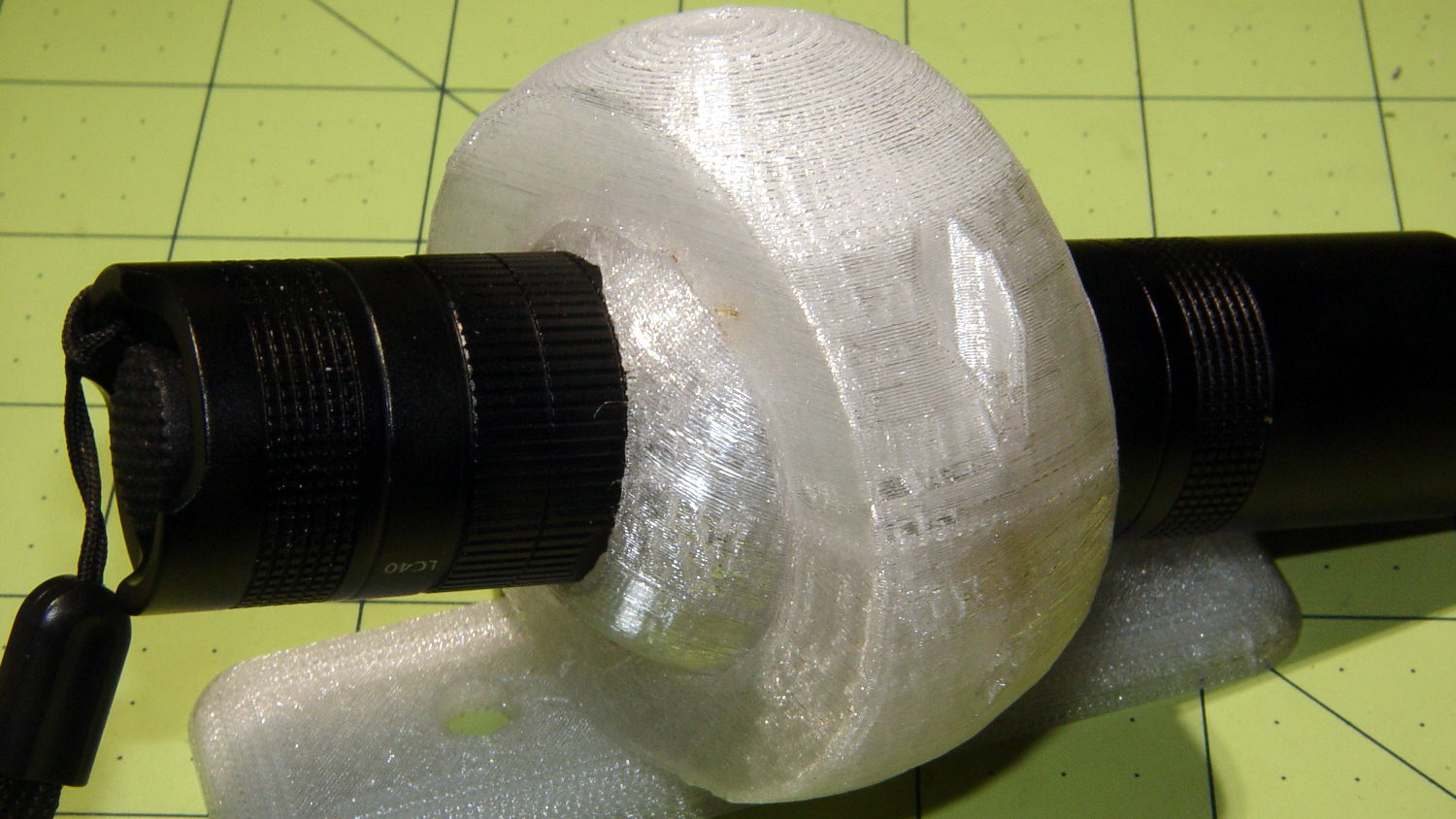
Mary’s bike has a tidier Anker LC40 in an earlier mount version:
Tour Easy – Anker LC40 – front
The Anker required an adapter to hold an 18650 cell in its 3xAAA-size body. The J5 V2 is resolutely 18650-only, which is fine with me.
The intent here is to find out whether this works, figure out the proper aiming point(s), then de-bulk the mount.
The next few posts will cover various bits & pieces of the design, because I must remember why I did things the way they turned out: sometimes the obvious choices didn’t work.
The Zzipper fairing originally mounted to the strut across the handlebars with a single 1/4-20 nylon screw on each side. Even with a nylon washer on the outside, the stress concentration cracked the polycarbonate sheet around the screws and brackets, so I designed & printed flat ABS plates to spread the stress over a larger area:
Fairing mount – inside
The tapered edges were supposed to be flexible, but the foam sheets sandwiched on both sides of the fairing actually provided most of the compliance. There’s another screw in the open hole binding the inner & outer plates together.
The mounts worked perfectly, even as they faded over the years. The fairings became quite scuffed during the course of our near-daily rides, but, heck, we’re also a bit scuffed and it’s still all good.
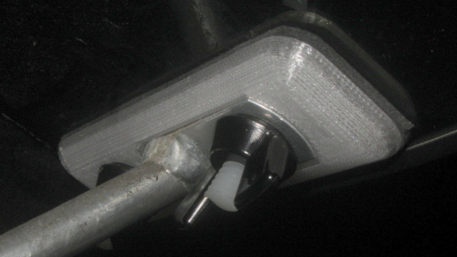
The new PETG inner plates seat on the bracket to nearly its full thickness:
Tour Easy – Zipper fairing plate – inside
The flashlight on the outer plate applies torque around the bolt which (I hope) the sides of the recess can resist. This is the absolutely key part of the design and, I’m somewhat ashamed to admit, took me far too long to figure out. What you don’t want: weird & fragile gimcrackery clamped onto the strut extending under the fairing’s edge, with the flashlight hanging far off to the side.
I modeled the fairing strut’s aluminum bracket as a 2D rectangle, plus a pair of chords, embiggened by a thread around the outside edge, minus the hole, then extruded to the proper height:
This file contains hidden or bidirectional Unicode text that may be interpreted or compiled differently than what appears below. To review, open the file in an editor that reveals hidden Unicode characters.
Learn more about bidirectional Unicode characters
The hole isn’t strictly necessary, as I punch out both screw holes as part of the plate assemblies.
The overall plate shape comes from the top half of a hull() wrapped around four squashed spheres:
This file contains hidden or bidirectional Unicode text that may be interpreted or compiled differently than what appears below. To review, open the file in an editor that reveals hidden Unicode characters.
Learn more about bidirectional Unicode characters
Then the inner plate is just a plate blank stamped with the bracket:
This file contains hidden or bidirectional Unicode text that may be interpreted or compiled differently than what appears below. To review, open the file in an editor that reveals hidden Unicode characters.
Learn more about bidirectional Unicode characters
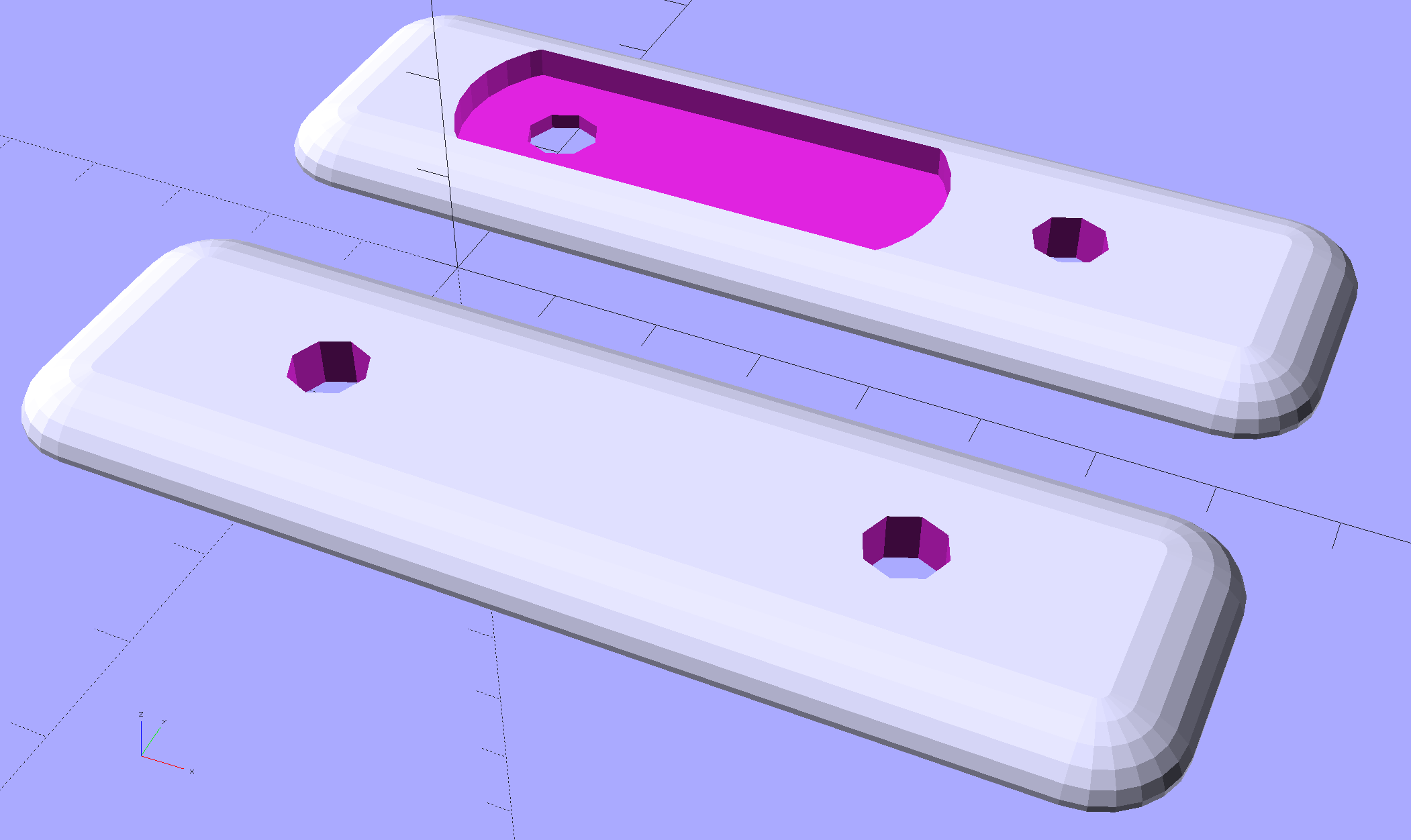
You’ll need a set for the side of the fairing without the running light:
Fairing Flashlight Mount – Plates – solid model
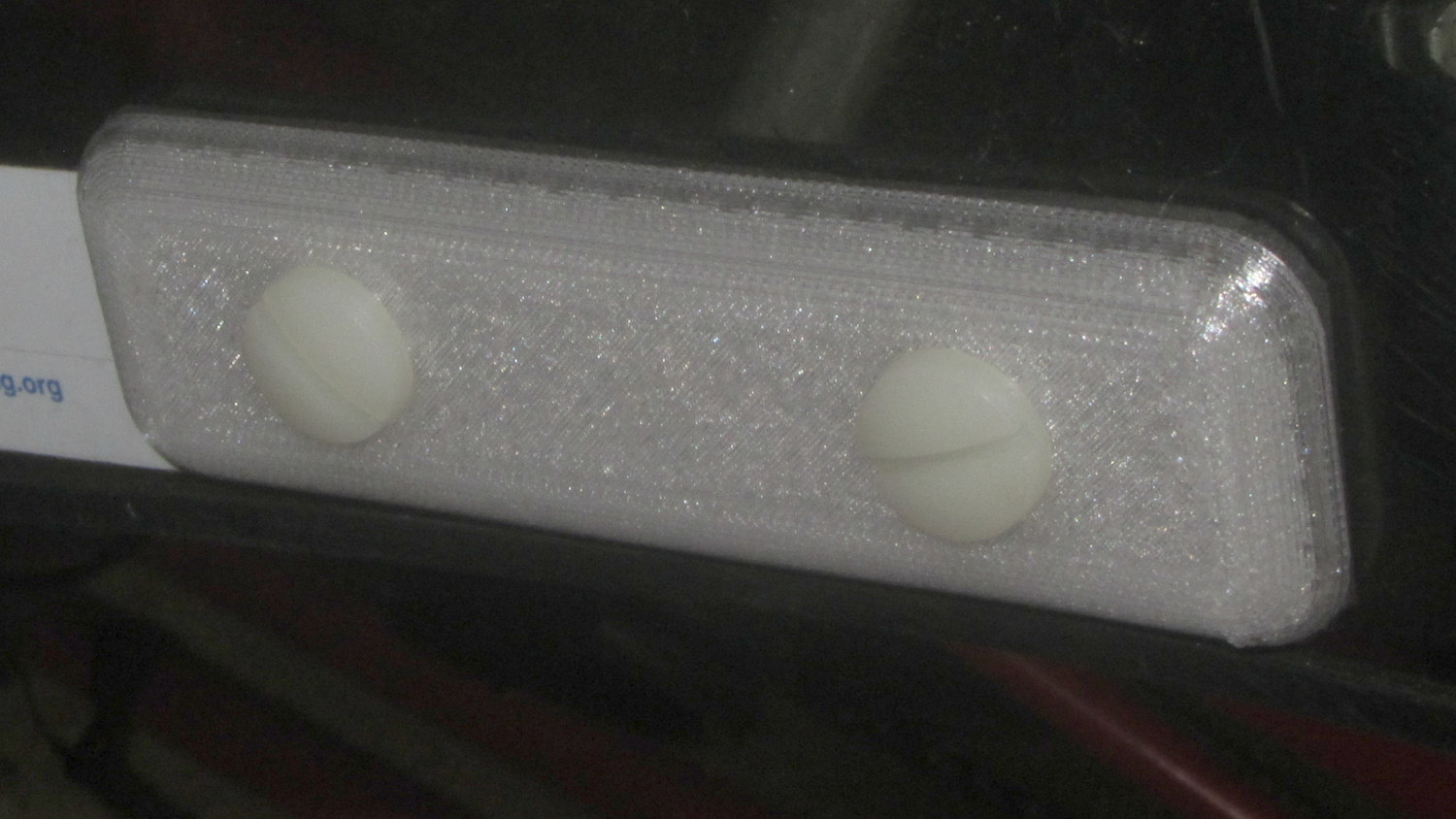
The outer plate looks reasonably sleek in real life, although that’s not the primary consideration:
Tour Easy – Zipper fairing plate – outside
You could replace the squared-off ends with simple half-circles, maybe stretched into stylin’ ellipse shapes, without too much effort.
I got out the screws, set up to cut them with a pull saw and miter box, then realized they are plastic. Put away the saw, got out the utility knife, and cut them to length with one firm push. No distorted threads, no dust, no muss, no fuss.
(*) Opinion: any headlight with non-replaceable, USB-chargeable cells is a toy. I can replace a discharged (or failed) 18650 cell in the middle of a ride, where a dead battery inside a spendy headlight would leave me in the dark. Might not matter for a DRL, but seems absolutely critical on night rides. ‘Nuff said.
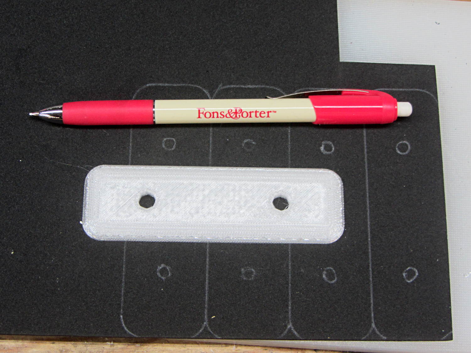
This worked surprisingly well to lay out black foam gaskets for new fairing mounting plates:
Black foam layout with ceramic fabric pen
Mary uses the Fons & Porter Mechanical Pencil to mark quilting patterns on fabric. It has, they say, a “strong ceramic 0.9MM white lead” with “water-soluble dyes” capable of both laying down a durable mark and washing out without leaving a trace. I don’t care about the latter, of course, but it did brush off reasonably well.
The next step involved running an X-Acto knife around the perimeter of the plate and punching the holes.
You can get colored ceramic leads (for small values of color) for use on other backgrounds.
Over the course of those six years I’ve ridden about 6 × 2500 = 15000 miles, maybe more, maybe less. I can ride at 15 mph for a while, but 12 mph seems a more reasonable overall estimate, making for a bit over 1000 hours. Figure the bike spends that much time sitting outdoors at the far end of the ride and you’re looking at what 2000+ hours of sunlight does to ABS.
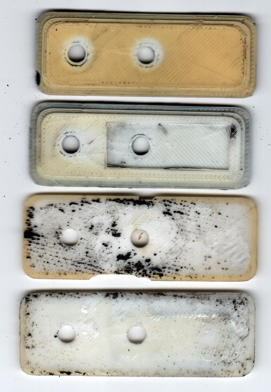
In addition to discoloration, the plates have become brittle, as shown in the chips in third one down, and permanently deformed due to the pressure of the nylon bolts compressing the black foam against the fairing.
A closer look at the top plate:
ABS Fairing Plates – 6 years – detail
My 3D print quality has improved a lot since then.
New plates of a different design are, as NASA puts it, “in work”.
The pix come from the new LiDE 120 scanner. It does a good job with the color, but has (for good reason) an essentially zero depth of field: if it’s not on the glass, it’s out of focus.
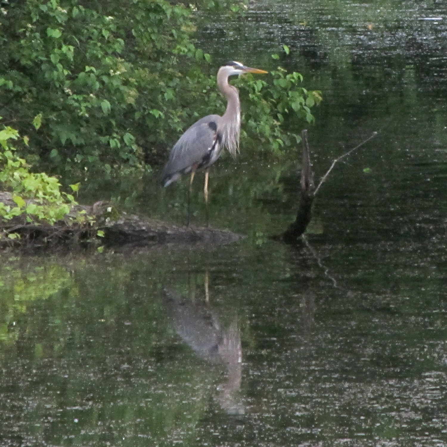
This Great Blue Heron caught a bright orange goldfish in the Vassar Farm Pond just before I rode past, spotted the scene, and fumbled my camera out of the underseat bag.
The heron hurked the fish down, with the abrupt right-angle bend in its neck marking the fish’s current location:
Great Blue Heron – swallowing
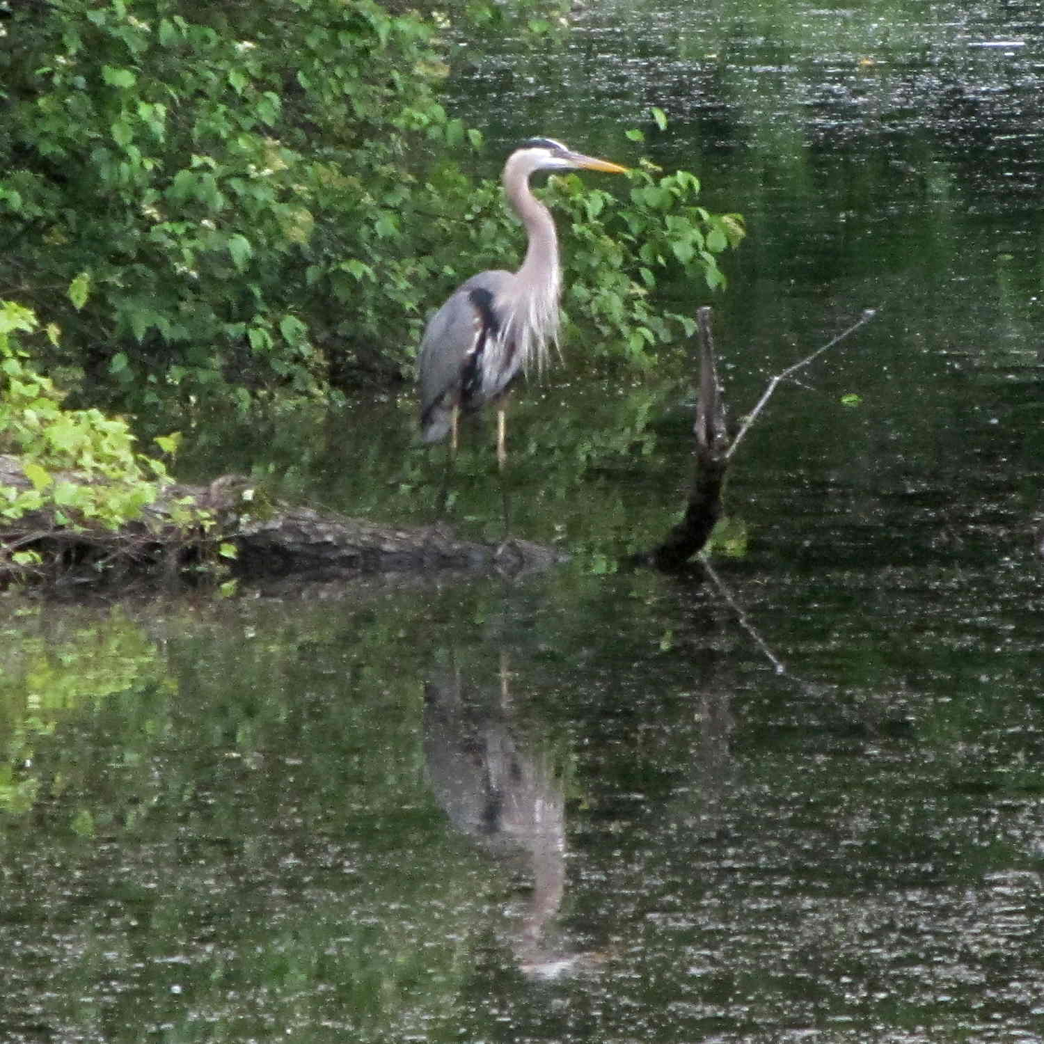
A bit of wiggling & jiggling put the meal in the right place and the bird relaxed:
Great Blue Heron – ruminating
A postprandial flight around the pond apparently settled the fish:
Great Blue Heron – takeoff
It landed on a snag a few dozen feet from where it started, then proceeded to look regal:
Great Blue Heron – idling
Those things really do look like pterodactyls in flight!