Ed Nisley's Blog: Shop notes, electronics, firmware, machinery, 3D printing, laser cuttery, and curiosities. Contents: 100% human thinking, 0% AI slop.
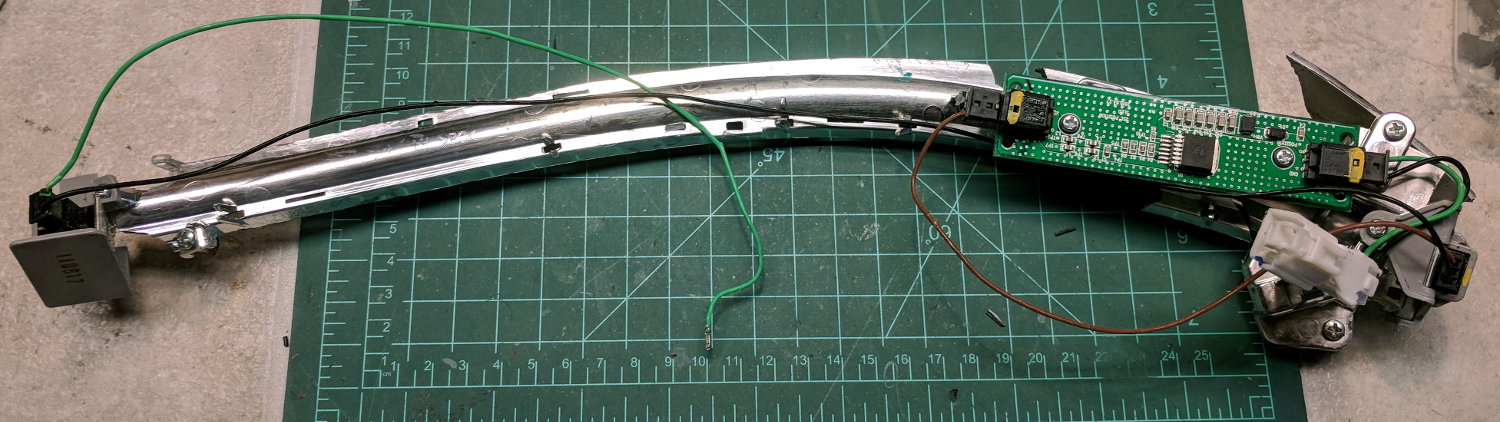
A high energy collision / accident / mishap in front of Adams Fairacre Farms (a.k.a., the grocery store) demolished 20 feet of their dry laid stone wall along Rt 44, flattened several bushes, gouged trenches in the grass, and scattered plastic debris into the parking lot. The remains of a headlight eyebrow running light emerged from a snow pile:
Eyebrow light – front
From the back:
Eyebrow light – back
Contrary to what I expected, it has one white LED at each end of the chromed reflecting channel, topped with a shaped plastic lens collecting the light:
Eyebrow light – Lens mount
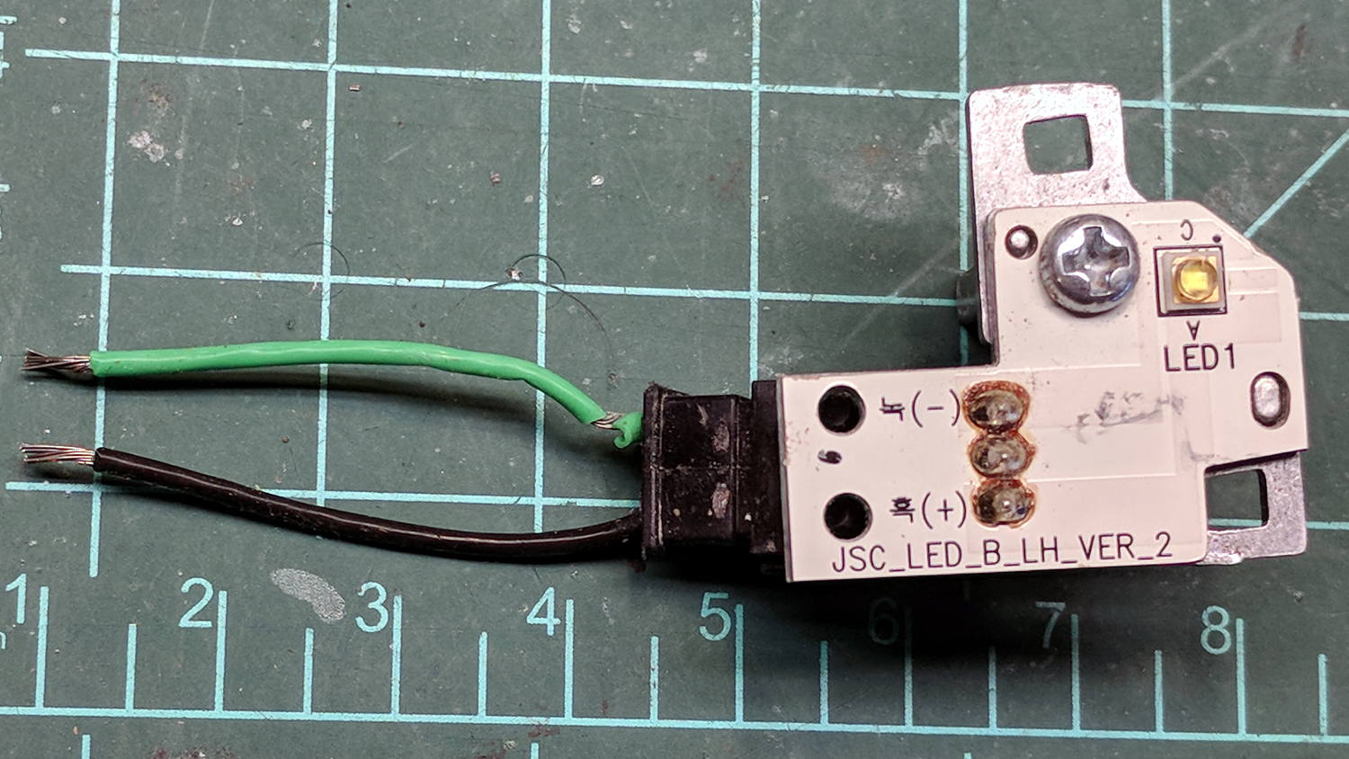
The LED PCBs are in series, which produced a backwards wire color code on one end:
Eyebrow light – LED PCB 1
The other end looked more reasonable:
Eyebrow light – LED PCB 2
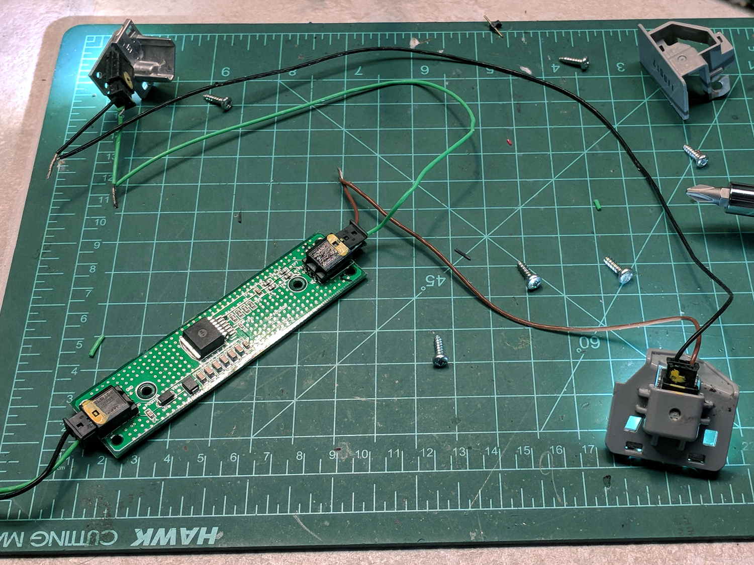
The white SMD LEDs draw 300+ mA at 3.6 V, so they’re obviously depending on external current limiting provided by the regulator PCB, sporting a TLE4242 linear current regulator and a handful of passives:
Eyebrow light – Regulator PCB
AFAICT, they didn’t use the chip’s PWM control input or its LED failure status output.
Extracting the various PCBs from the wreckage and reconnecting the wires produced a satisfactory result:
Eyebrow light – resurrection
The regulator limits the LED current to 120 mA at any input from a bit over 7 V to well past 12 V, with each LED dropping 3.0 V.
Dunno what I’ll use this junk for, but at least I know a bit more about eyebrow lights. The chip date codes suggest 2010 and 2012; perhaps linear regulators have become passe by now.
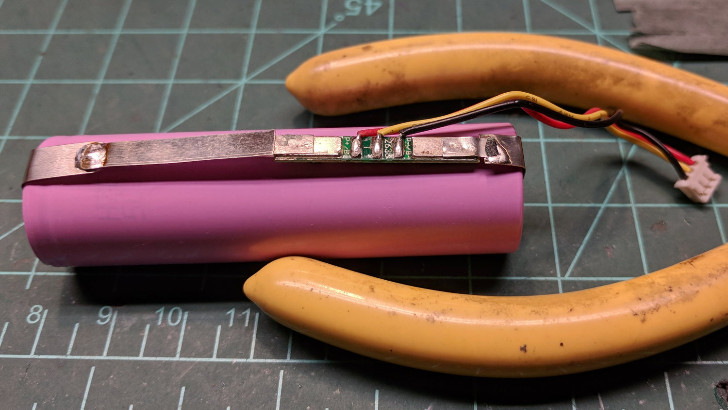
The transplanted protection PCB goes between the tabs, with a nickel strip snippet because I didn’t cut the old strip in the right place:
Fly6 – battery replacement – PCB
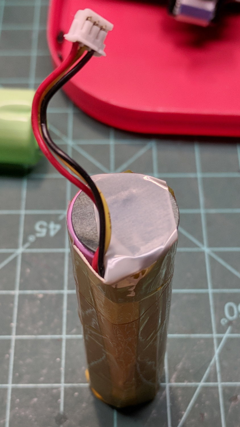
The PCB goes under a manila paper layer, the ends get similar caps, and the whole affair receives an obligatory Kapton tape wrap:
Fly6 – battery replacement – endcap
Reassembly is in reverse order. I now know the Fly6 will reset / start up when the battery connector snaps into place, but, because it emits identical battery-charge beeps when it starts and shuts off, there’s no way to tell what state it’s in. I don’t see any good way to install the ribbon cable from the LED PCB before plugging in the battery, so just blindly press-and-hold the power button to shut it off.
After an overnight charge, it makes videos of my desk just fine and will, I expect, do the same on the bike.
Now that I’ve taken the thing apart, I should open it up and tinker with the (glued-down) camera focus adjustment to discover whether:
It’s slightly nearsighted and, thus, correctable or
Following all the steps recommended by Cycliq Tech Support didn’t improve the situation. It’s just under two years old and thus outside the warranty, so they advised me to buy their new, not-quite-released-yet Fly6, now with Bluetooth / ANT+ / phone app / shiny, but still with a non-replaceable battery.
Seeing as how the Fly6 works as well as it ever did, apart from the minor issue of shutting down both dependably and intermittently, the problem is almost certainly a bad battery. Cycliq does not offer a repair service, nor a battery replacement service; being based in Australia probably contributes to not wanting to get into those businesses. You’re supposed to responsibly recycle the Whole Damn Thing when the battery goes bad. Which, inevitably, it does.
Protip: anything with a non-replaceable battery is a toy, not a tool.
The most recent ride gave some evidence supporting a bad battery. The first shutdown happened after about half an hour and it gave off three battery status beeps (four = full charge, as at the start of the ride) when I restarted it a few minutes later. It shut down again a few minutes later while we were stopped at a traffic signal and gave off one lonely charge beep when I reached back to restart it, indicating a very low battery voltage. The battery voltage (and the number of startup beeps) increased with longer delays between shutdown and restart, but after the first shutdown it’s never very enthusiastic.
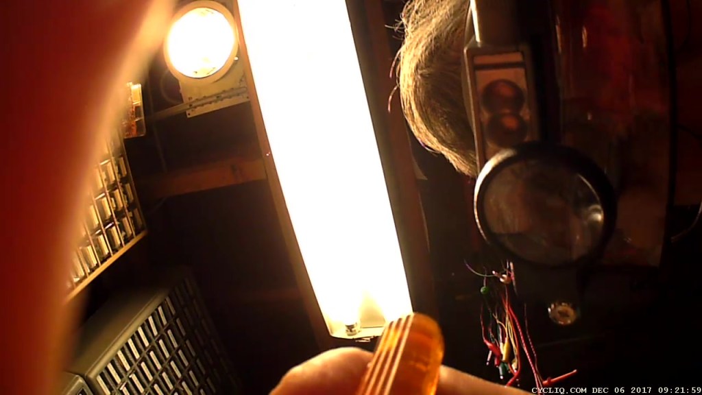
Having nothing to lose, let’s see what’s inside:
Cycliq Fly6 Teardown from inside
Don’t do as I did: you should extract the MicroSD card before you dismantle the camera.
Remove the rubber plugs sealing the four case screws:
Fly6 – Exterior screw plugs out
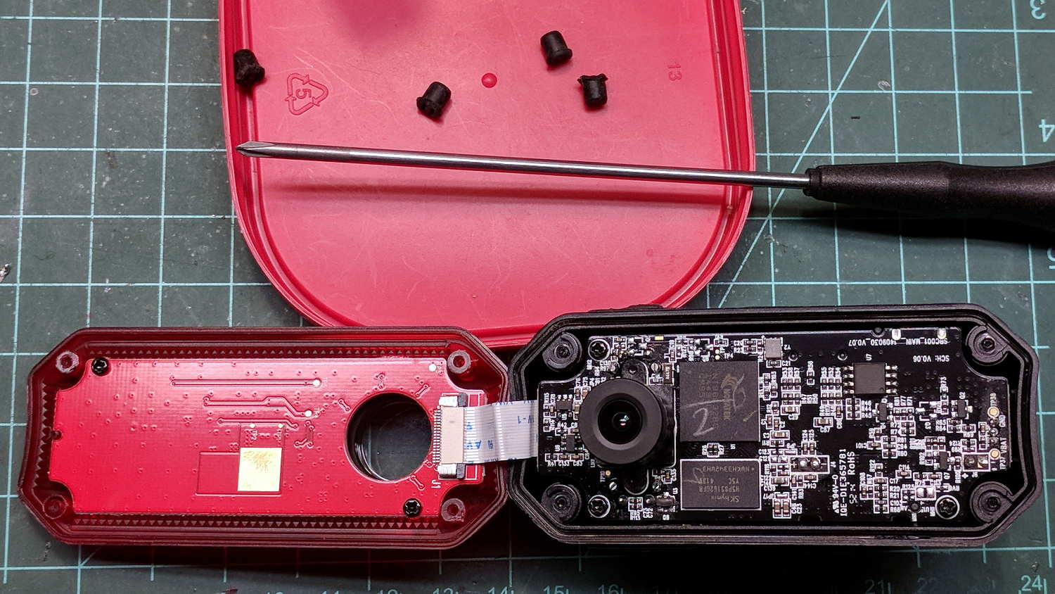
The case pops open, with a ribbon cable between the LEDs and the main circuit board:
Fly6 – Case opened
Pull the ribbon cable latch away from the connector before pulling the cable out.
It’s amazing what you find inside a blinky taillight these days:
Fly6 – PCB Top side
I’m sure there’s a fancy 32 bit RISC computer in the big chip, along with plenty of flash ROM just below it. The clutter over on the right seems to be the power supply. Yeah, it has a camera in addition to blinky LED goodness, plus USB charging, so eight bits of microcontroller aren’t nearly enough.
Note: the case screws are slightly longer than the PCB retaining screws:
Fly6 – Case and PCB Screws
The underside of the PCB has even more teeny parts, along with, mirabile dictu, a battery connector and (most likely) battery charging stuff:
Fly6 – PCB Underside
A plastic piece holds the “Rechargeable Li-Ion Battery Pack” in place:
Fly6 – Battery in place
A strip of gooey adhesive holding the mic and speaker wires in place also glues the battery strap to the case, but it will yield to gentle suasion from a razor knife.
Pause to count ’em up:
Four case screws (longer)
Three PCB screws
Two battery screws
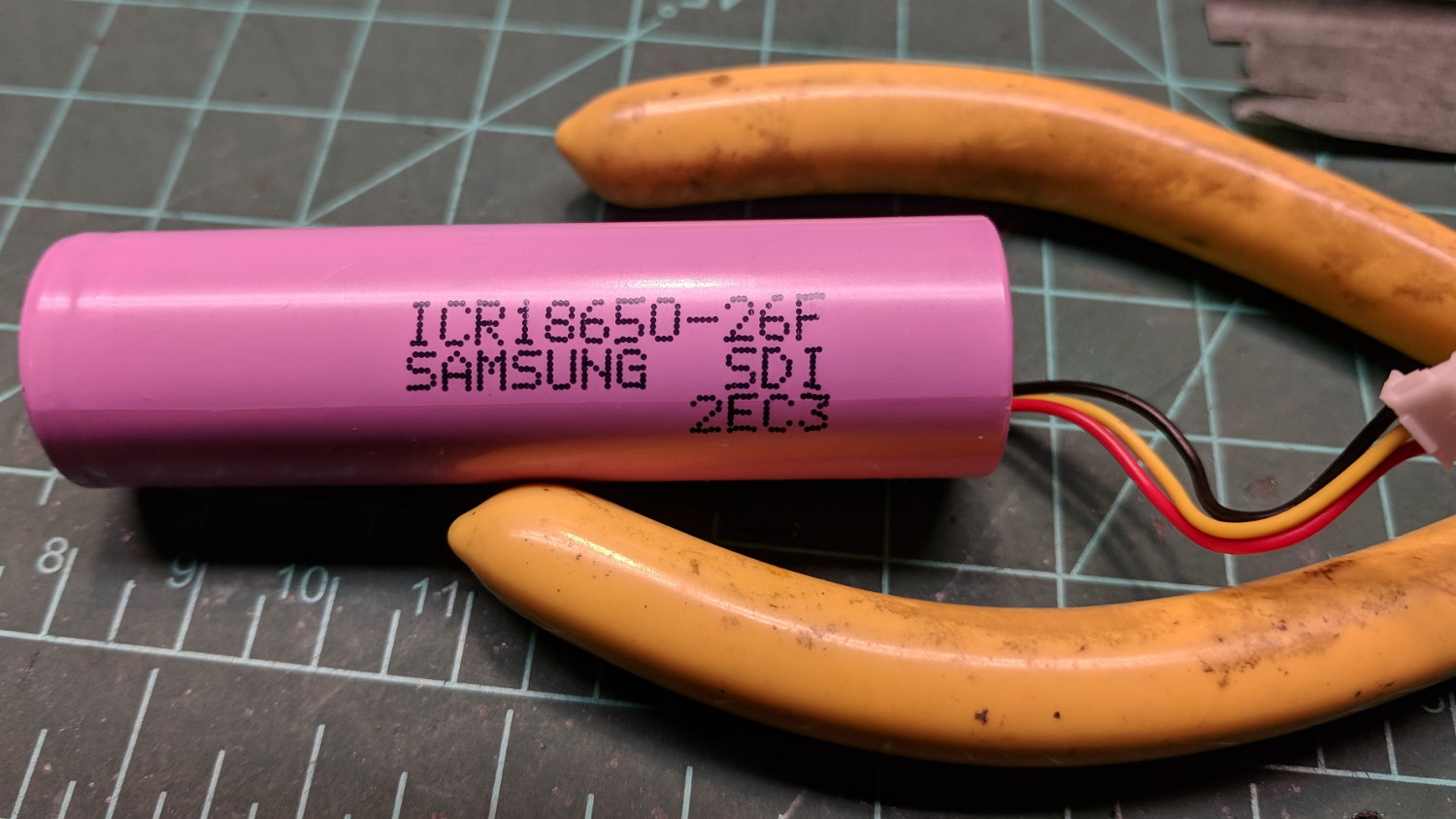
It looked a lot like an ordinary 18650 lithium cell to me and, indeed, it is:
Fly6 – Battery – label
More razor knife work removes the outer shrinkwrap. The cell has a protection PCB under the black cardboard cover:
Fly6 – Battery Protection PCB – on 18650 cell
I don’t know what the yellow wire does:
Fly6 – Battery Protection PCB – wire side
The FS8205A on the left may be an SII S8205 protection IC preset and packaged for a single cell:
Fly6 – Battery Protection PCB – components
After all that, yeah, it’s a dead battery:
Fly6 OEM 18650 – EOL – 2017-12-06
The red curve shows the in-circuit charge state after taking it apart, the green curve comes from charging the bare cell in my NiteCore D4 charger. I have no idea what the nominal current drain might be, but a 0.25 Ah capacity is way under those Tenergy cells.
A new cell-with-tabs should arrive next week, whereupon I’ll solder the protection circuit in place, wrap it up, pop it back in the case, and see how it behaves.
“High Endurance” means it’s rated for 5000 hours of “Full HD” recording, which they think occurs at 26 Mb/s. The Fly6 records video in 10 minutes chunks, each weighing about 500 MB, call it 1 MB/s = 8 Mb/s, a third of their nominal pace. One might reasonably expect this card to outlive the camera.
The Fly6 rear camera on my bike started giving off three long beeps and shutting down. Doing the reformatting / rebooting dance provides only temporary relief, so I think the card has failed:
Sandisk Extreme Plus vs. Samsung EVO MicroSD cards
The Fly6 can handle cards up to only 32 GB, which means I should stock up before they go the way of the 8 GB card shipped with the camera a few years ago.
Some back of the envelope calculations:
It’s been in use for the last 19 months
The last 22 trips racked up 88 GB of video data = 4 GB/trip
They occurred over the last 6 weeks = 3.6 rides/week
Call it 250 trips = 1 TB of data written to the card = 32 × capacity
That’s only slightly more than the failure point of the Sony 64 GB MicroSDXC cards. The Fly6 writes about a third of the data per trip, so the card lasts longer on a calendar basis.
So now let’s find out how long the Samsung cards last …
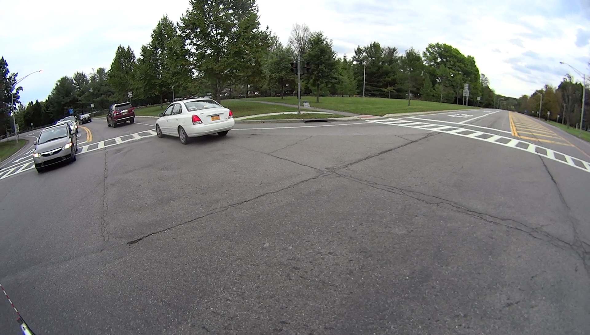
T=0: You can’t tell, but the signals for Hooker Avenue have been yellow for several seconds and are about to turn red:
Raymond – Left on Red – 2017-10-11 – 1
T+3: The opposing signals have been red for a while, but nobody much cares about that:
Raymond – Left on Red – 2017-10-11 – 2
T+11: Right-turning traffic (with a green arrow) blocks his path, so he just drops to a dead stop in the middle of the intersection:
Raymond – Left on Red – 2017-10-11 – 3
T+14: Finally! All clear for a left on red:
Raymond – Left on Red – 2017-10-11 – 4
When a cyclist delays a driver for two, maybe three, seconds, even while riding legally, outrage occurs.
And, yeah, I’ve made mistakes, too. Happens to everybody. Cyclists seem to arouse disproportionate outrage, so I try very hard to ride within the rules and the lines.
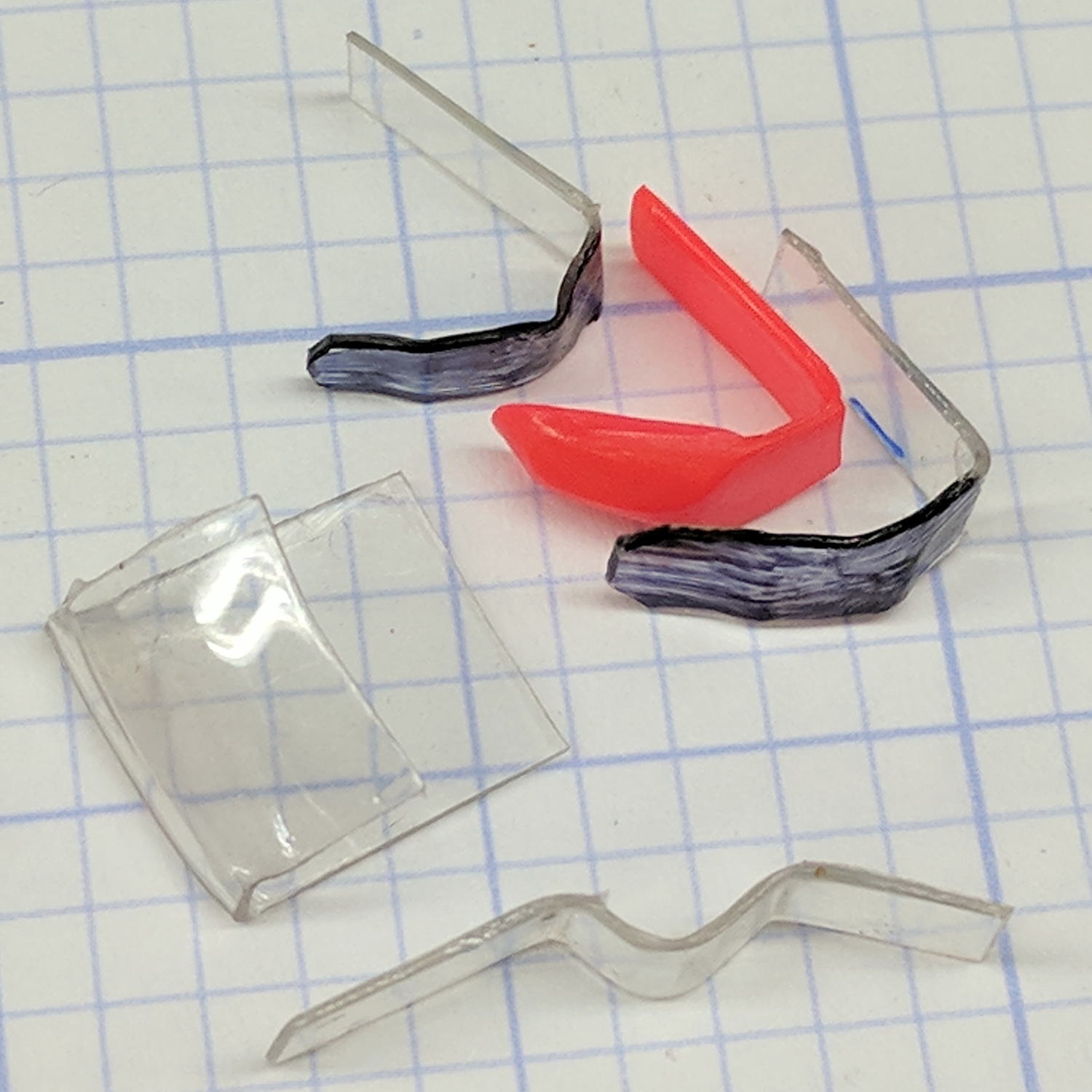
Over the course of a few weeks, both of the indicators in the SRAM grip shifters on my bike snapped off. Having recently touched my parallel jaw clamp assortment, it occurred to me I could mold snippets of polypropylene sheet (saved from random clamshell packages for just such a purpose) around the nose of a clamp and come out pretty close to the final shape:
SRAM Shift Indicator – shaped replacements
A hot air gun set on LOW and held a foot away softened the polypro enough so a gloved thumb could squash it against the jaw. Too much heat shrinks the sheet into a blob, too little heat lets the sheet spring back to its original shape.
The flat tab of the original indicator is about 1 mm thick. I found a package of 47 mil = 1.2 mm sheet with one nice right-angle bend and ran with it.
Because I expect sunlight will fade any color other than black, that’s the Sharpie I applied.
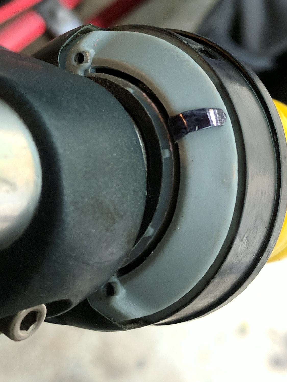
They don’t look as awful as you might expect. The rear shifter, minus the cover:
SRAM Shift Indicator – rear detail
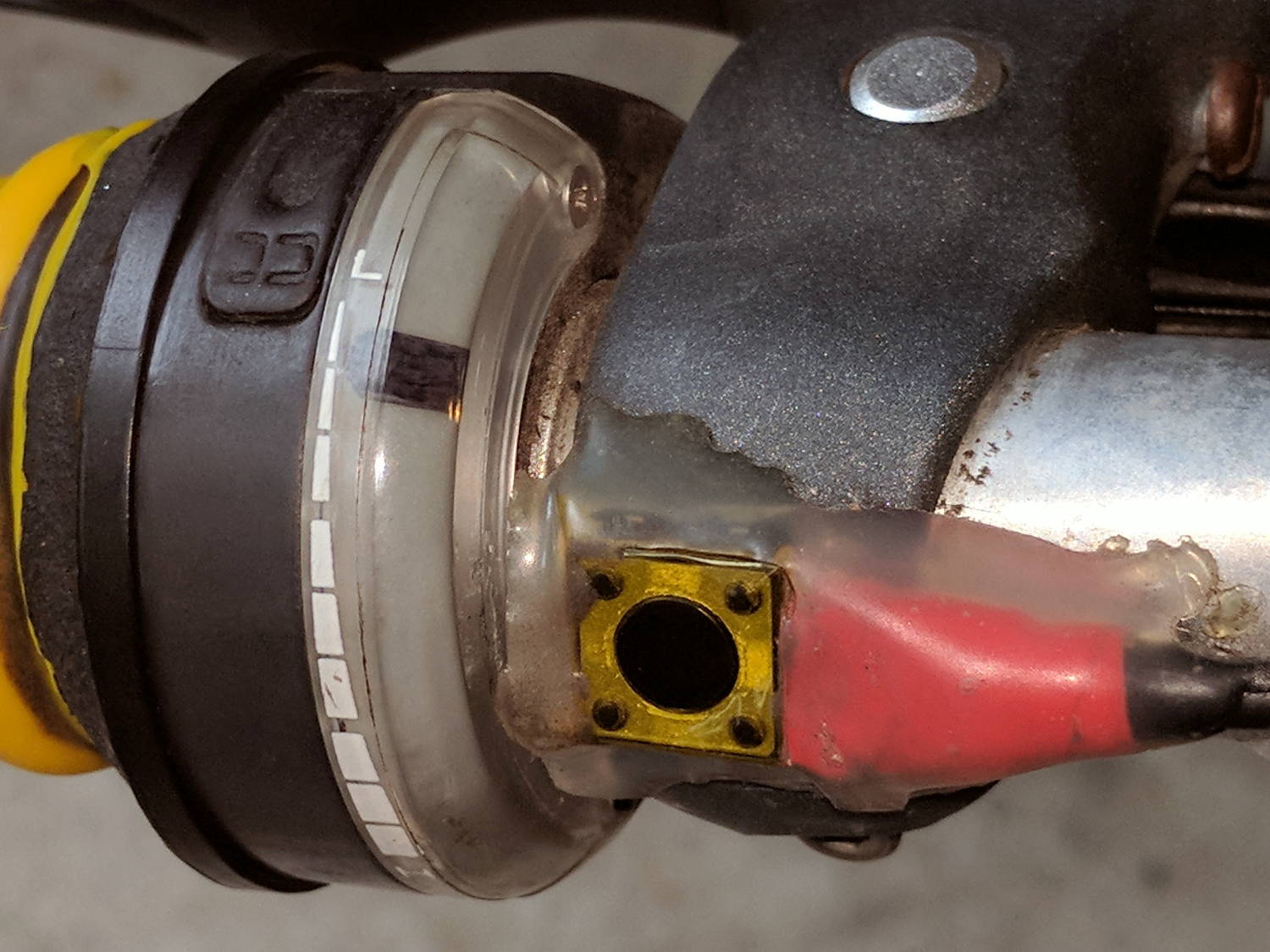
The front shifter, with cover installed and HT PTT button below the still-good Kapton tape:
SRAM Shift Indicator – front assembled
The transparent covers press the OEM indicators down and do the same for my homebrew tabs. I expect the Sharpie will wear quickly at those contact points; next time, I should tint the other side.
They’re rather subtle, I’ll grant you that.
Now, to see if they survive long enough to make the worry about a brighter color fading away a real problem…