The object being to light up a falling object at a known position, I ran off the usual Physics 1 spreadsheet relating position, time, and speed for the ideal case:

I wanted the flash to occur when the object was about 200 mm below the trigger point (the laser-photodiode beam-break sensor), which turns out to be, conveniently enough, 200 ms after the drop. A 1/25 = 40 ms shutter time allowed for the ±10 ms or so of jitter that I assumed would be due to the CHDK motion-detection script, but I did not have a good estimate of the delay from motion detection to shutter opening; I assumed it would be nearly zero. That meant the LED flash must occur about 50 ms earlier, at about 150 ms from the drop and 60 ms from the beam break; assuming I dropped the object about 30 mm above the beam break sensor.
Soooo, I baked those numbers into an Arduino program (more on that later), lashed the hardware together, and fired it up.
The beam-break sensor worked, the Arduino code worked, the LED and Xenon strobe fired, but all the pictures were black: the LED triggered the motion detection script, but the flash occurred either before or after the shutter opened.
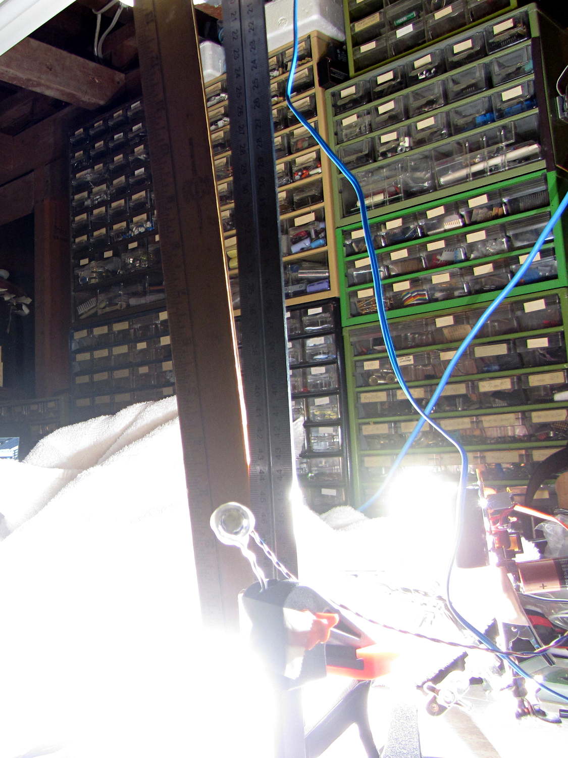
After considerable adjustment of times, twisting of knobs, and general flailing around, this happened:

If you look very, very closely, you can see a thin rectangular object at the top edge of the picture, just to the left of the machinist’s scale supporting the beam-break sensor, which, in turn, is barely visible to the left of the mysterious rectangle.
The round eye-like object peering at you from 1/3 up the scale is the 10 mm white LED that triggered the motion-detection script. It’s dark, because that flash ended long before the shutter opened.
More flailing around stopped the object in the middle of the image:

The motivation for dropping a ruler: it’s long enough that you’re bound to catch at least part of it and the graduations let you estimate distances and times fairly accurately. That’s after you manage to catch at least part of it, of course.
Increasing the flash delay caught it just before it hit the white towel causing the retina-burn glare at the bottom:
A bit of detail from another picture with the ruler near the middle shows that the 1 ms Xenon strobe flash really does stop the action:

Even though the initial timing estimates were completely wrong, there’s some hope this will actually work…