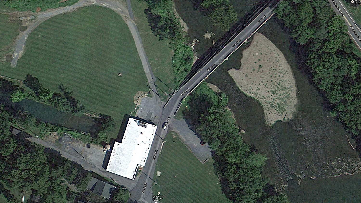
I’m grinding uphill at about 5 mph on Jackson Drive, in the middle of the surprisingly good shoulder, with the bright-red Planet Bike taillight blinking away to the rear. I am not inconspicuous, but …
You’ll never see the one that kills you:
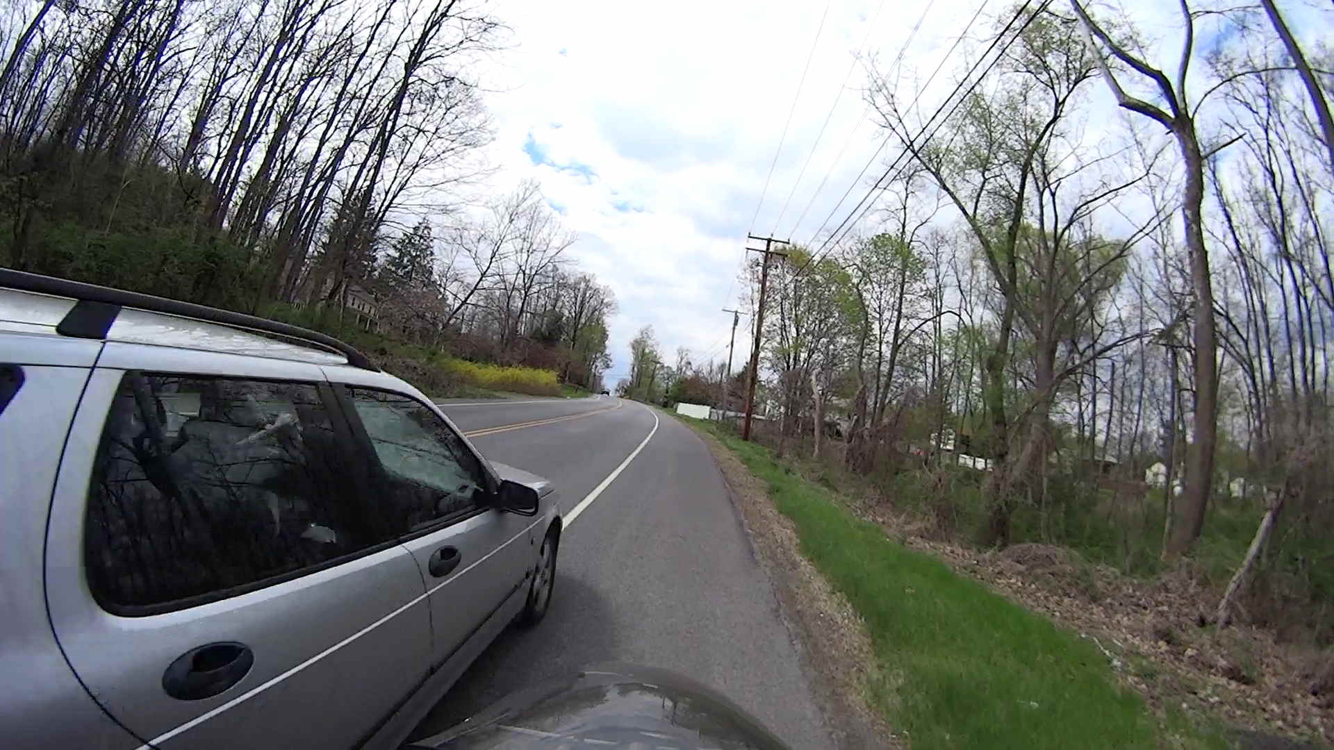
The speed limit is 40 mph = 60 ft/s. The door-to-shoulder clearance might have been the better part of a foot; the mirror didn’t quite clip my arm.
The license plate is legible in the original image, although I’ve blurred it here:
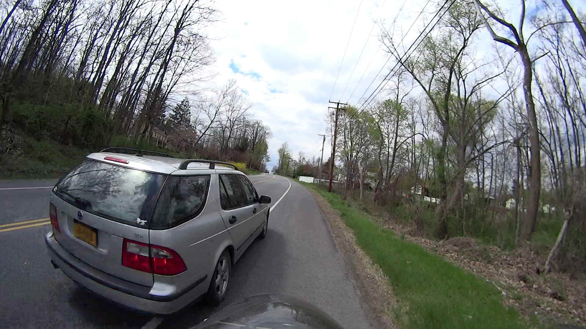
Adrenaline is wonderful stuff; I caught up with him at the next light … uphill and 1/3 mile later:

I said “Hey!” When he looked over, I explained I needed a face to go with the plate and pointed to the camera. He said he was really, really, really sorry.
I’ll not ascribe to malice what can be explained by distraction; if he wanted to hassle me, I’d be dead now. Most likely, it’s one of those distracted driving things that happens to all of us … to some, alas, far more frequently than to others.
Took a while for the shakes to stop.
Put down that damn phone / tablet / burger and pay attention!
[Update: Still images captured from the Sony HDR-AS30V helmet camera, recorded at 1920×1080 60 fps.]