Ed Nisley's Blog: Shop notes, electronics, firmware, machinery, 3D printing, laser cuttery, and curiosities. Contents: 100% human thinking, 0% AI slop.
It’s one of those 1920-ish things with the impeccable stonework and bronze casting that you couldn’t possibly duplicate nowadays. But, at least twice between then and now, somebody thought it’d be a Good Idea to decorate it with what look to be Genuine Christmas Tree Lights:
Provincetown Pilgrim Memorial – detail
The most recent lamps and wires seem to be restrained by plastic clips glued onto the face of the stone:
Provincetown Pilgrim Memorial – lamp detail
A previous generation drilled small holes and inserted metal pins that didn’t survive in a salt-spray environment, so I guess plastic seemed like the right answer.
Adafruit’s Neopixels are RGB LEDs with a built-in current-limiting 400 Hz PWM controller and a serial data link. Successive Neopixels aren’t synchronized, so their PWM cycles can produce serious current spikes.
Lighting up just the red LED in two Neopixels at PWM 16/255 produces this current waveform (at 10 mA/div):
Neopixel current 10 mA – 16-0-0 0-1
Each red LED draws about 20 mA, so when the two Neopixel PWM cycles coincide, you get a nasty 40 mA spike. When they don’t coincide, you get a pair of 20 mA pulses. Those pulses walk with respect to each other at a pretty good clip; the oscillators aren’t trimmed to precision.
Lighting up three Neopixels with PWM 16/255 on the red does exactly what you’d expect. The horizontal scale is now 100 µs/div, making the PWM pulses five times wider:
Neopixel current 10 mA – 16-0-0 0-1-2
The narrow spike comes from the brief shining instant when all three Neopixels were on at the same time. Now you have three PWM pulses, each with slightly different periods.
Remember that these are PWM 16/255 pulses. When they’re at full brightness, PWM 255/255, there’s only a brief downtime between pulses that last nearly 2.5 ms and they’ll overlap like crazy.
Obviously, the more Neopixels and the lower the average PWM setting, the more the average current will tend toward the, uh, average. However, it will have brutal spikes, so the correct way to size the power supply is to multiply the number of Neopixels in the string by the maximum possible 60 mA/Neopixel… which gets really big, really fast.
A 1 meter strip of 144 knockoff Neopixels from the usual eBay supplier will draw 144 x 60 mA = 8.6 A when all the pulses coincide. Worse, the supply must be able to cope with full-scale transients and all the fractions in between. A husky filter cap would be your friend, but you need one with a low ESR and very high capacity to support the transients.
No wonder people have trouble with their Neopixel strings; you really shouldn’t (try to) run more than one or two directly from an Arduino’s on-board regulator…
Yeah, I’m sure that’s not what it means, but, still…
I don’t understand how the total cost of a nontrivial something shipped halfway around the planet can be less than the price I’d pay to return it. I’m certain it involves massive subsidies and mysterious cash flows that never break the surface of the eBay “Buy It Now!” pond.
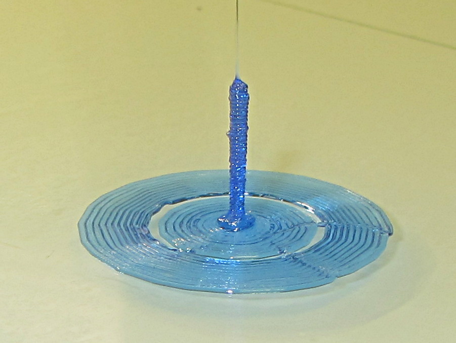
Sliced with Slic3r for PETG at 1 mm/s, with fans in full effect. It sits amid a 5 mm brim, inside a skirt that uses 15 mm of filament, giving it a Washington Monument aspect.
The challenge was to print a 0.7x9.0 cylinder, which doesn’t work well with a 0.35 mm nozzle. Instead, I went with 0.9 mm diameter. The result measures 1.1 mm over all the obvious bumps, so it’s surprisingly close. The “nail head” at the bottom most likely comes from the hot end depressurizing as it suddenly transitions from 15 mm/s in the brim to 1 mm/s for the cylinder.
Fairly obviously, you can’t print something like that at full speed (50 mm/s was claimed for a Rep 2 and I don’t believe that for an instant). Indeed, it’s such a pathological model that Slic3r’s minimum layer time and small perimeter settings had no effect; I had to manually set the extrusion speed to 1 mm/s in order to make it work. Plus adding that brim, because I knew it wouldn’t stand by itself.
Other than that, printing it was no big deal.
A picture from that M2 forum discussion suggests you can go crazy with this stuff:
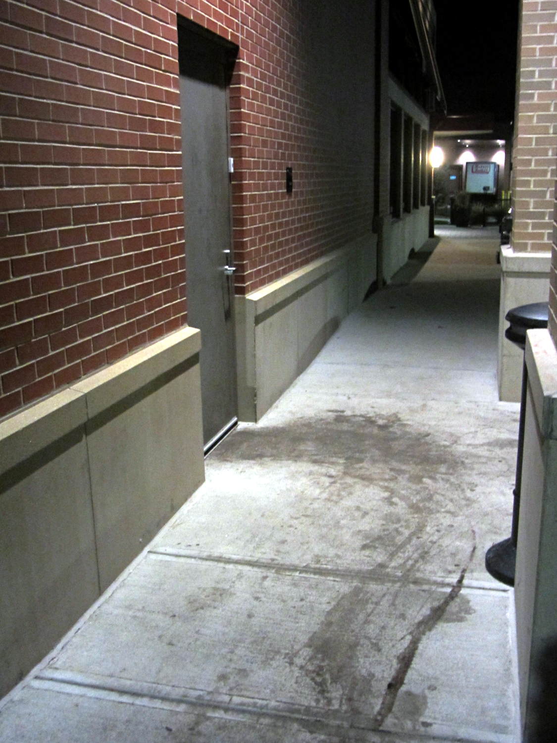
The stains appeared black-red under the cold LED light and my first thought went along the lines of “Somebody dragged a corpse out of the kitchen!”:
Restaurant back door
The dumpsters sit off the sidewalk behind me on the left, so, most likely, they just have a bit of trouble maneuvering overstuffed trash cans and grease tanks around the door. At least, that’s what we hoped.
Notice how the door hinges the wrong way? Perhaps the architect never anticipated moving waste from the kitchen to the dumpsters.
The food was OK (we did not order the Chef’s Special Long Pig), but their overly loud “background music” reverberated far too long inside a cavernous room with hard walls. We gave it 2/10: would not eat there again.