This showed up when I looked at our APRS tracks after a recent ride:

Poking around a bit showed the target:
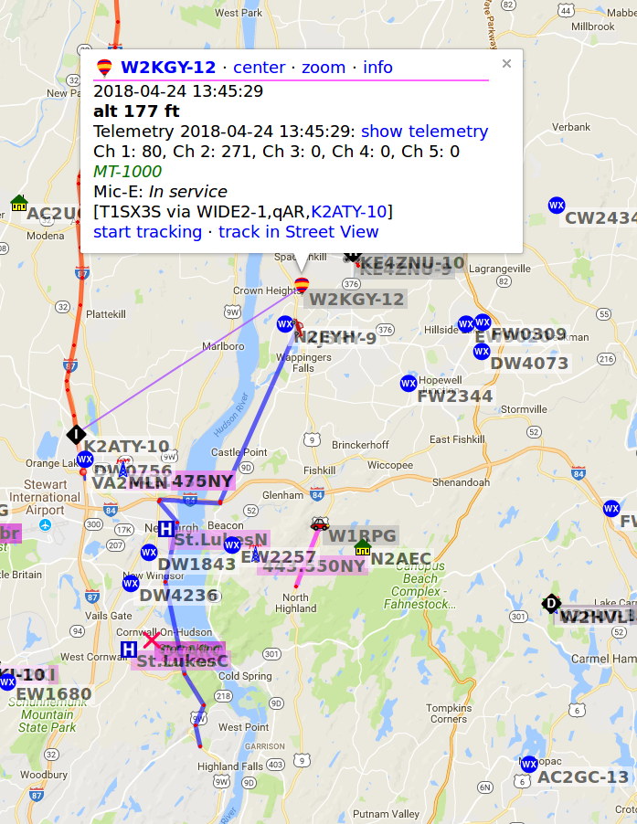
Contrary to what I thought, it didn’t come up the Hudson River from West Point:

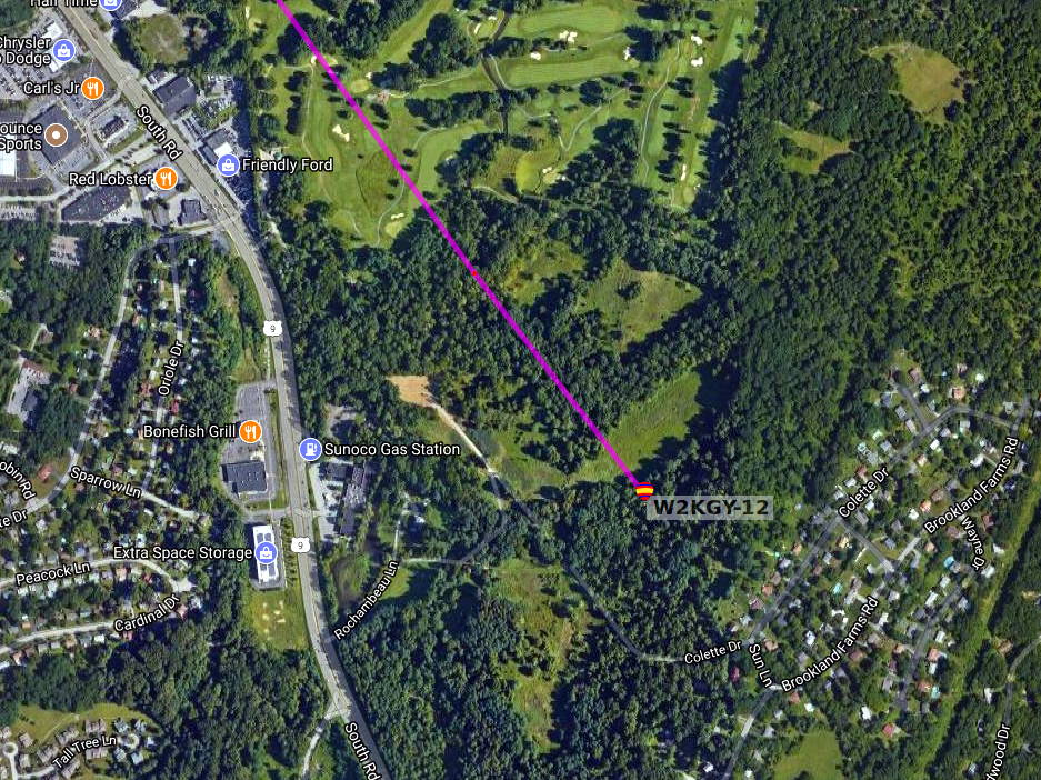
Knowledge of the Universal Law of the Conservation of Perversity informs you a balloon will never land in the middle of a putting green:
Apparently the launch is part of a regular class project at West Point. Good clean fun!