I have often asserted, in public, in writing, that you can’t change the speed of a fan’s BLDC motor by varying its voltage, because the fan controller generates the waveforms responsible for the motor speed based on its internal timing.
A pair of BLDC blowers recently arrived and a quick test showed I’m pretty much completely wrong:

The data points come from this blower:
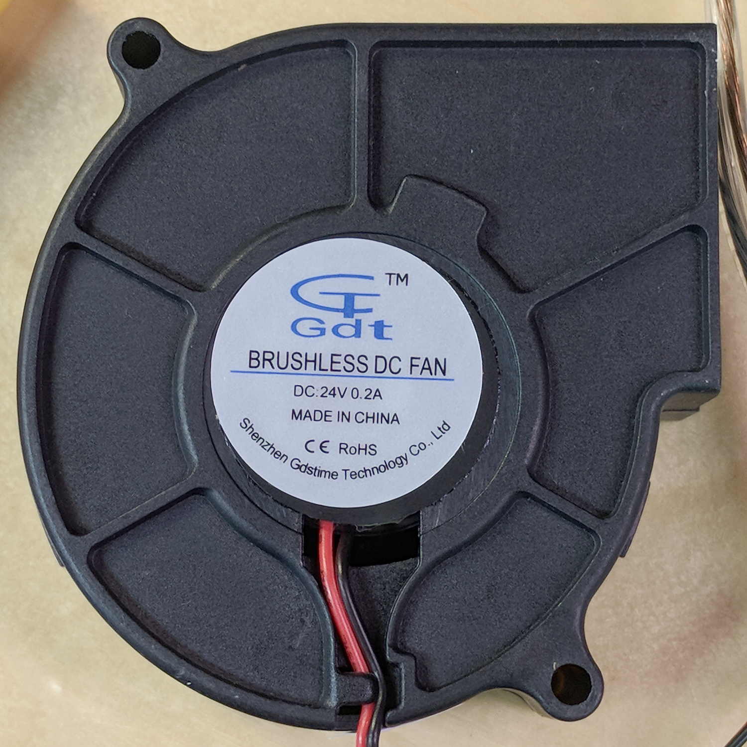
The blower specs from the eBay listing:
75MM 24V Brushless DC Blower Cooling Fan Exhaust Fan
- Dimension:75(L)x75(W)x30(H)mm
- Connector:2Pin-PH2.0
- Rated Voltage: DC24V
- Rated Current: 0.2±10% Amp
- Rated Speed: 3800±10%rpm
- Air flow:1.8CFM
- Noise: 23±10%dBA
- Bearing Type: Sleeve
- Life: 35000 hours
- Cable Lenght: 32cm(12.5in)
- Weight: 75g/pcs
The case is about 75 mm × 75 mm × 30 mm, so the generic part number seems to be 7530, with many variations. However, they all seem to resolve to the same blower with different models drawing different current at specific voltages (clicky for more dots, JPG blurriness in original):

The blower in hand roughly corresponds to the bottom line of the 24 V section:
- 0.21 A
- 4000 RPM
- 16.3 CFM
- 1.1 inch H2O pressure
- 43 dBA
There’s a gross discrepancy between the eBay 1.8 CFM and the chart 16.3 CFM, but the other parameters seem within handwaving distance and, yo, it’s from eBay. ‘Nuff said.
The graph up top shows the results with an unrestricted output opening.
For more realistic results with some resistance to air flow, I taped a small anemometer to the blower output:
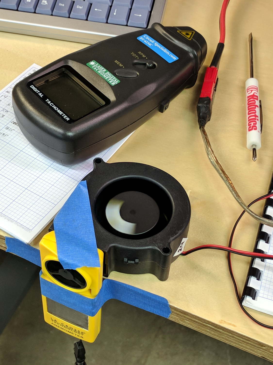
Which produced:

In very round numbers, the anemometer aperture is 400 mm², so the 9 m/s air flow at 24 V works out to 3.6×10⁻³ m3/s = 0.13 CFS = 7.6 CFM. Which is maybe half the 16.3 CFM spec, but they’re surely using a fancier anemometer with much lower back pressure. Close enough, anyway. Fer shure, 1.8 CFM is wrong.
Completely blocking the inlet with a plastic sheet to simulate the blower pulling air from, e.g., a vacuum table:
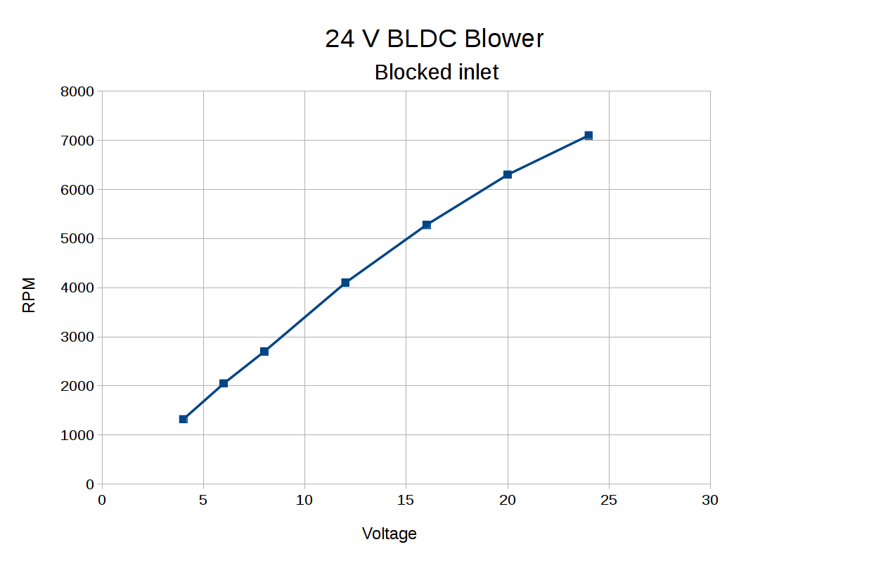
The RPM varies more linearly with voltage when the blower isn’t accelerating any air.
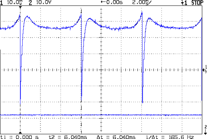
Some current waveform show why you really shouldn’t run fans in series to “split the power supply”, as seems common in 3D printers with 24 VDC power supplies.
From a 24 V supply, the current drops to 50 mA every 75 ms (200 mA/div):
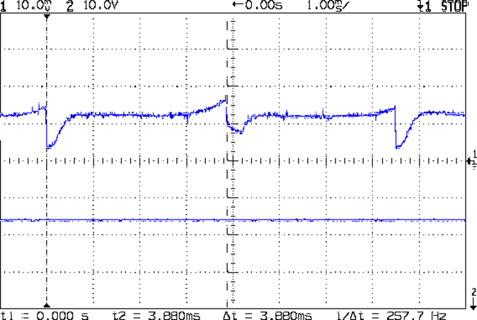
From a 12 V supply, even weirder things happen (50 mA/div):
Note that you can’t reduce the fan’s supply voltage by applying PWM to the current, as happens in essentially all 3D printers for “speed control”. Basically, PWM turns the fan off several hundred times every second, which does not modulate the voltage.
I have no way to measure pressure, but if the 1.1 inch H2O number comes close to reality, the blower can produce 1.5 lb of clamping force per square foot. Which isn’t a lot, granted, but it might suffice for paper and vinyl cutting.
The DRV10866 BLDC fan controller doc from TI is completely unrelated to the blower in question, but gives a reasonable introduction to the subject.

Comments
13 responses to “Monthly Science: BLDC Fan Characteristics”
For cutting paper in my laser cutter, I’ve had some good success using Krylon easy tack spray adhesive applied to a plywood waste board. Acts like the sticky mat you use with craft cutters. You can also just get a Cricut or Silhouette mat, they are designed for paper and vinyl.
Back when I thought the HP 7475A plotter had enough downforce to become a cutter, I picked up a set of those cutting mats and hung them on a shelf bracket to keep ’em straight. They’ve been hanging ever since, reminding me to not make preemptive purchases.
Perhaps a vacuum table will hold them flat enough and, combined with bCNC’s height mapping, a simple drag knife should work fine.
Dave Gingery has a simple manometer in his centrifugal fan book. Searching on gingery manometer brings up the relevant book right away. As I recall, he’s got the information on making and using the appropriate pitot tubes, too.
Mercury FTW!
I think the flow should be about zero, so I can (probably) get away with a barb fitting jammed into a vacuum channel. It’ll certainly become a Monthly Science posting. [grin]
Thanks for the pointer …
IIRC (the book is in the barn, maybe later), the manometer uses water and vinyl tubing for the guts. Looks like Amazon has a variety, basic to differential & digital at varying prices. ($15 to $180 according to the search engine pics)
One’s deep on my round-tuit stack; a lightly supercharged engine model is deeper in that stack. (I have an old analog CPAP machine with a tiny centrifugal blower. Right size. Might even work.)
A nudge arrived suggesting MEMS barometric pressure sensors. Might made sense: no water spillage and Yet Another Arduino Project.
That looks good! Nice price, too.
If that’s on a PWM controller, then the caps short across the fans into the MOSFET; it’s a Bad Thing for the transistor, at least in principle.
If you’re splitting a DC supply, why not put a buck converter on the supply, run them at their rated voltages, and be done with it?
5uF into IRLZ44N… what could go wrong :)
I still want to have the option of running them at less then 100% with PWM… didn’t try it yet though :)
Granted, the guy who blew the MOSFET on his RAMBo board did it with maybe 470 uF, but the cap still doesn’t do the right thing.
[…] A simpleminded MOSFET circuit provides PWM drive for the BLDC blower: […]
[…] The fan turns at 2600 RPM at 50% PWM, close enough to the 2580 RPM I measured at 12 VDC. […]