Feeding 50% PWM at 1 kHz into the simpleminded 24 V BLDC driver produces the results you’d expect:

The upper trace shows the MOSFET drain voltage, the lower trace is the current at 200 mA/div.
The fan is connected from +24 VDC to the drain, so it’s getting power when the MOSFET is turned on and the drain is at 0 V. When the MOSFET turns off, the drain goes high and the drain current flow stops dead in its tracks.
Of course, the fan current doesn’t drop to zero, because inductance. The drain voltage rises until the MOSFET body diode enters avalanche breakdown, whereupon the energy in the magnetic field burns down across the voltage difference as usual.
Weird current waveforms happen all the time:
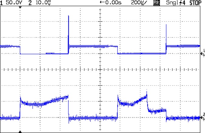
Or like this:
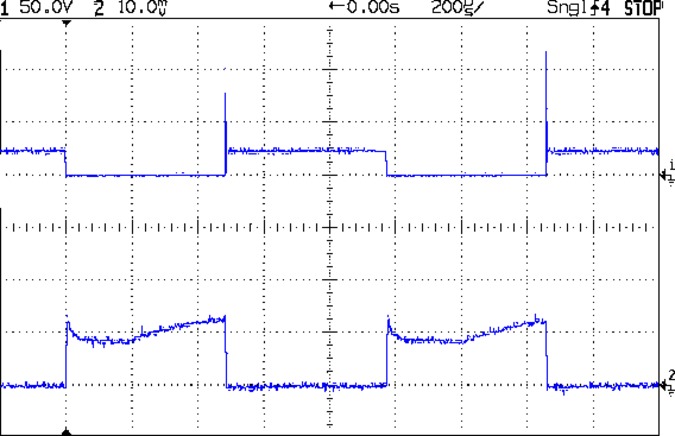
I think we’re looking at a sensorless BLDC controller trying to figure out the fan RPM from the back EMF after rebooting during each PWM cycle.
The fan turns at 2600 RPM at 50% PWM, close enough to the 2580 RPM I measured at 12 VDC.
In any event, the drain voltage in the upper trace tops out around 120 V, because the IRF530 MOSFET has a 100 V absolute maximum VDS spec: you’re watching avalanche breakdown happen. A transistor rated for 14 A of avalanche current isn’t in much danger quenching only 200 mA, though, so it’s all good, apart from slapping the fan with -100 V across what used to be its +24 V supply.
A closer look at the turn-off end of the pulse:

Eyeballometrically, the drain current decreases at 100 mA / 500 ns = 200 kA/s with the drain voltage clamped at 120 V, during the division just right of center. The other side of the fan sits at +24 VDC, so the effective inductance looks like 480 μH = 96 V / 200 kA/s. I’m unwilling to tear the blower apart just to measure the motor winding inductances.
In any event, because we’re seeing the output of a 24 V three-phase fan controller being reverse-biased at 100 V, I doubt those numbers mean anything, other than that you shouldn’t PWM-chop the current going into a BLDC fan controller, of course.

Comments
2 responses to “BLDC Fan vs. PWM: Inductive Spike”
Given that the fan itself doesn’t stop abruptly the instant you turn off the MOSFET, how much of what you see is down to the fan turning into a generator as it winds down to a standstill?
Haven’t a clue! Generation should produce an AC waveform, but (I think) it wouldn’t be visible outside the motor without commutation around the (wye? delta?) windings. The inductive energy in the windings, however, produces a net DC current that must go somewhere, so it punches through the transistors.
I think, anyhow, but I’m not a BLDC guru!