One of the two air pockets in the token padding had popped:
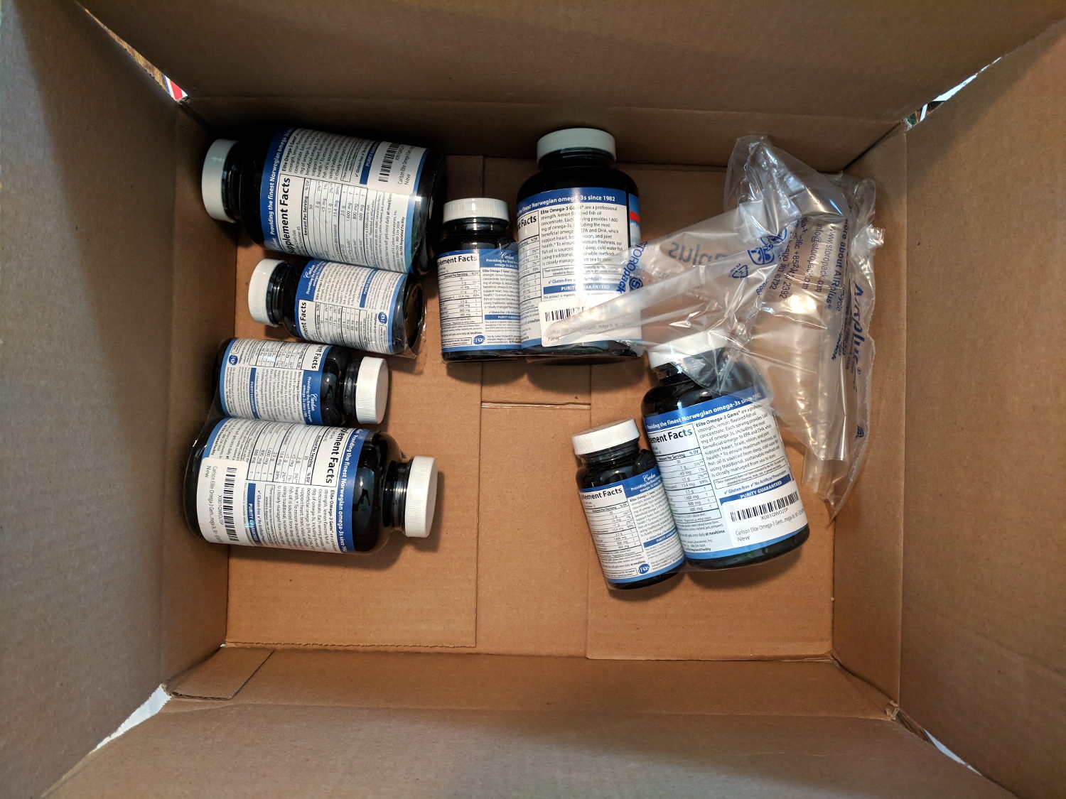
Fortunately, they were plastic bottles with rugged contents, so I suppose the packaging was up to the task.
The Smell of Molten Projects in the Morning
Ed Nisley's Blog: Shop notes, electronics, firmware, machinery, 3D printing, laser cuttery, and curiosities. Contents: 100% human thinking, 0% AI slop.
Who’d’a thunk it?
One of the two air pockets in the token padding had popped:
Fortunately, they were plastic bottles with rugged contents, so I suppose the packaging was up to the task.
A Sigelock Spartan hydrant spotted in Franklin PA:

It’s certainly the shapeliest hydrant I’ve ever seen.
Of course, you need a special tool to remove the main cap, after which some internal lockwork releases the side caps, after which you can spin the valve stem recessed under the top cover. One hopes all those little bits continue sliding and releasing after a few decades, but … the status quo apparently isn’t all that good, either.
I’ve been coaching a high-school student (and his father!) on the intricacies of building a self-balancing robot; they’re doing all the hard work and I’m running interference with techie bugs. This one turned out to be particularly nasty.
It seems all versions of Raspberry Pis have an I2C bus hardware problem preventing them from working correctly with Adafruit’s Bosch BNO055 (yes, “bee en oh zero five five”) Absolute Position Sensor. The problem has been variously diagnosed as being due to the Pi’s inability to handle clock stretching in arbitrary parts of the I2C transaction and the BNO055 chip’s exquisite sensitivity to I2C bus levels, but it’s worse than that.
Reading the chip’s temperature sensor once every second produced this output:

He now knows why you must always leading-zero-fill binary values.
The shorter values say the chip ran at 26 °C, which means the longer values have a bogus binary 1 in bit 7. I2C bus transfers proceed MSB-first, so the Pi occasionally reads a bogus 1 at the first clock transition while reading the single temperature byte from the BNO055.
After some flailing around, we observed two types of I2C bus transactions.
Without clock stretching:

With clock stretching:

Contrary to what one might think from the lead-in description, the non-stretched version always produces the incorrect leading bit and the stretched version usually delivers the correct result.
He had previously installed the clock stretch workaround and we verified it was active. Turning it off had no effect, as did turning it back on again. The value uses units of the SCL period, so the modified value of 20000 produces 20×103 counts of 1/(100 k bit/s) = 2 s, far longer than any delay we observed. In fact, the default 640 μs would (apparently) suffice for the BNO055.
I installed the Adafruit-recommended pullup resistors and we verified they had no effect.
We noticed, but I did not record, nasty positive-going pulses on both SDA and SCL which were not due to noise or supply problems. As far as I can tell, the Pi does not maintain control over the I2C bus lines during some phases of the transaction, perhaps when the BNO055 invokes clock stretching, allowing the pullups to produce narrow upward glitches crossing the logic threshold. This will merit further study.
The solution, such as it is, seems to require slowing the I2C bus transactions to 25 kb/s, by inserting a line in the /boot/config.txt file:
dtparam=i2c_arm_baudrate=25000
... dummy line to reveal underscores ...
Slowing to 50 kb/s produced intermittent errors, while 25 kb/s seemed to completely eliminate them. This contradicts suggestions of proper operation at any speed other than the default 100 kb/s. Note: this applies to a single-byte data value and longer transactions remain to be tested.
I want to verify that the lower rate also eliminates the glitches, which will require running the Pi with the scope plumbed into its guts for some time. For obvious reasons, he’d rather get the robot working, so, until he encounters more problems, I won’t see the hardware …
Update: There’s now a way to do I²C with software bit-banging in a reasonably easy way. Thanks to Simon Blake for pointing this out!
While staying at the Witherup House in Franklin PA, I found :

It was published in 1946, when memories were fresh and ISBNs hadn’t yet been invented:

Paging through it, I found a photo similar to one I’d grown up with (clicky for more many dots):

None of those guys look like Dad.
Many of the events in World War II made little sense until the declassification of the Enigma decryptions and the ensuing Ultra / Magic programs showed the value of weaponized math …
A loud crack during a windy thunderstorm announced this mess:

Some deft bow saw work cut it down to size:

Whereupon our neighbor arrived home and we dragged the carcass off the driveway.
Fortunately, it missed everything important, as have several recent branch falls in our yard. The same cannot be said for the many downed trees around the immediate area from recent storms; some folks are hurtin’ bad.
Verily, houses (and trees) are trouble!
One of my Tektronix AM503 Hall Effect Current Probe Amplifiers (B075593, for future reference) lost its DC Level zero-ing capability:

The front-panel knob produced only positive output voltages from maybe 50 mV to the amp’s upper limit around 200 mV (into a 50 Ω termination, Tek not being one to fool around with signal quality & bandwidth). Other than that, the amp seemed to work fine, but you definitely want a 0 V baseline corresponding to no current through the Hall probe.
The manual includes troubleshooting recommendations:
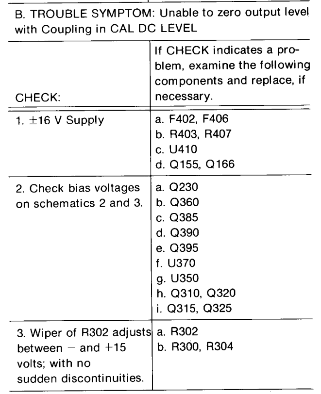
Because I didn’t understand the circuitry, I check the supply voltages, then started at U350, the differential amp rubbing the DC level knob against the input signal, and worked outward in both directions (clicky for more dots):

The PCB looks like this:

U350 is the round epoxy package in the the square spider-leg array over on the far left. Contrary to what you (well, I) might think, the index mark denotes pin 16, not pin 1:
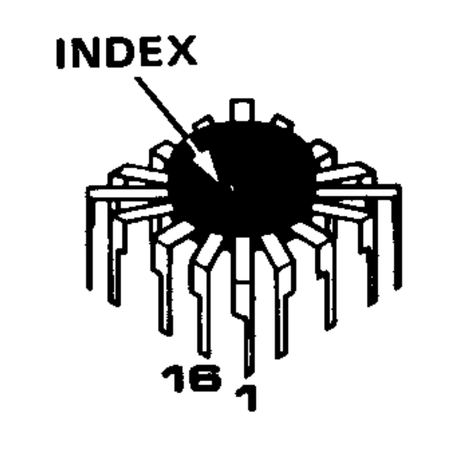
Which puts pin 1 at the upper right corner of the package on the PCB. The part listing in the manual says MICROCKT,LINEAR:VERTICAL AMPLIFIER / SELECTED, which makes perfect sense given Tek’s oscilloscope business; if you needed a high-speed differential amplifier, that’s what Tek’s internal catalog would surely suggest. Newer AM503 revisions use somewhat less unobtainable op amps, although they replace the DC Level knob with one of those newfangled microcontroller thingies for some sweet auto-leveling action.
Nothing seemed out of order. The unable-to-zero condition pushed the bias voltages off the expected values, but nothing seemed completely out of whack / stuck at the rails / broken.
The problem turned out to be in Q230, the first item on Tek’s checklist after the power supplies, even though its bias voltages looked OK. It produces the “Attenuated AC Signal” seen above and lives on another page of the schematics:

Q230 is clad in the natty red heatsink in the PCB picture above. CR226 is the metal TO-18-ish can partially hidden by the orange-red-brown ribbon cable from the DC Level pot.
For future reference, C234 and C244 aren’t installed in this PCB; they’d fit in the conspicuously vacant spots to the right and in front of Q230.
What may not be obvious at a first glance: Q230’s pins sit in teeny individual sockets installed in the PCB. One might remove and reinstall Q230, should one be so inclined and, given that it’s the first active device after the input attenuator, one might imagine such an action being necessary after a catastrophic oopsie.
At this late date, finding a suitable dual JFET would be … difficult, even were one were willing to compromise on the hermetic metal TO-78A package.
Seeing as how Q230 has been sitting quietly in its socket for the last three decades, I proceeded cautiously:
I heroically refrained from pulling it completely out of its socket to dab DeoxIT on the pins; JFETs being notorious for susceptibility to static damage and, likely, lube would make no difference anyway.
Fired that devil up and the DC Level knob resumed doing exactly what it should:

The output now has the usual ±200 mV range centered at 0 V. The waveform shows a 100 mA signal at 50 mA/div, produced by a bench supply into a 100 Ω power resistor switched by a DC-DC SSR.
Whew & similar remarks.
Moral of the story: it’s always the connector!
About five miles south of Franklin PA along the Allegheny River Trail, the Belmar Bridge carries the Sandy Creek Trail over the Allegheny River:

The gap in the rivets along the main truss show where someone pried off the bronze plaque surely commemorating the bridge. The scarred surface suggests a bronze-steel battery was in effect for quite some time.
I’m a sucker for big ironwork:

It’s a look at engineering done in the days of slide rules and limited data, when overengineering wasn’t nearly as bad as ensuring the thing never, ever fell down.
The bolts holding the beams and struts together show considerable confidence:

Each bolt counts as single point of failure, but this one can rust for a long, long time before the risk becomes important.
Each of those gazillion rivets required a crew to heat white hot, shove into the hole, and hammer tight.
They don’t make ’em like that any more and I suppose it’s a good thing …

