Ed Nisley's Blog: Shop notes, electronics, firmware, machinery, 3D printing, laser cuttery, and curiosities. Contents: 100% human thinking, 0% AI slop.
Long ago, in a universe far away, my buddy Mark One mis-read a unit of measure and ended up with a trailer load a’ Tektronix Thermal Paper. It carried a silver-based emulsion requiring constant refrigeration, so he stashed about a pallet of paper canisters under every raised floor on the IBM Poughkeepsie campus. Even though the raised floor acreage has dropped dramatically, some of it may be there to this very day.
The Pixel 3a produces exceedingly useful low-light images, mostly by having Google’s software compensate for its tiny lens and minimal light-capture area, with the downside of turning a peaceful night scene into harsh daylight.
Several of this year’s praying mantises set up shop in the decorative grasses bracketing the front door:
Praying Mantis – brown wing covers – in grass
We found their egg masses, formally called ootheca, attached to the stems in mid-October:
Praying Mantis egg mass A
They feel like rigid urethane foam and seem eminently protective:
Praying Mantis egg mass B
We’ll cut around the masses when it’s time to clear out the dead grass next spring. I was tempted to bring one inside, but dealing with a gazillion tiny mantises in a few months would be daunting.
As you might expect by now, I harvest various bits & pieces from the PCs falling off the trailing edge of my assortment. The bag of obsolete DRAM recently floated to the top of the heap:
DRAM Assortment – overview
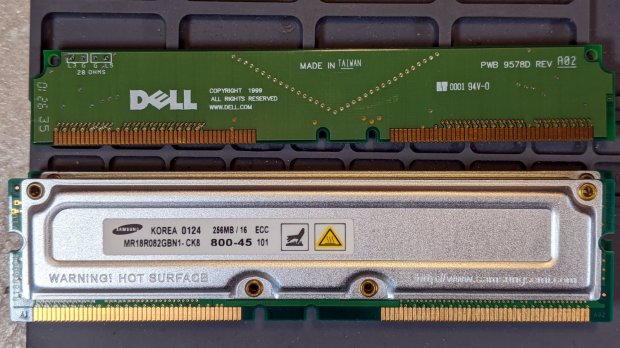
Half a gig of ECC RAM from what might have been a fire-breathing Pentium Pro box:
DRAM Assortment – 256 MB ECC
The PCBs along the top apparently filled vacant memory slots.
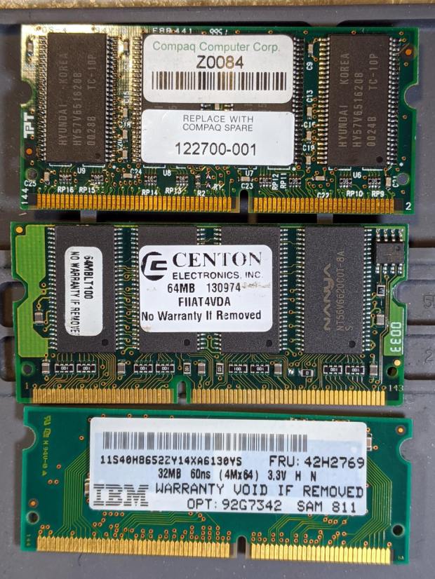
Some 32 and 64 MB DRAM from a few IBM laptops I turned into picture frames:
DDR2 DRAM in assorted sizes & speeds:
DRAM Assortment – PC2 DDR
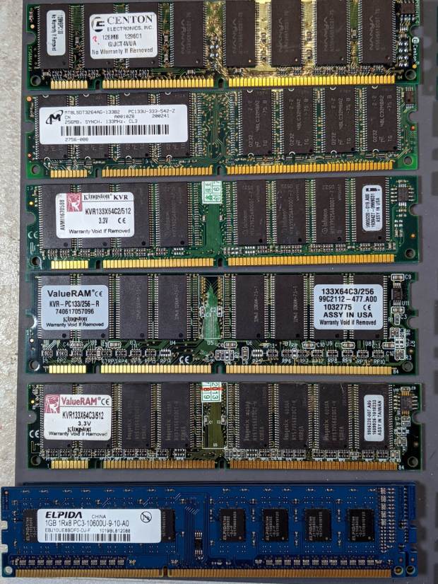
PC133 DDR DRAM, with four sticks of 1 GB PC3 along the bottom:
DRAM Assortment – PC133
If you look closely, you may see something you can use. No reasonable offer refused …
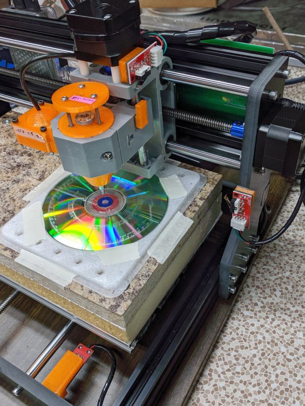
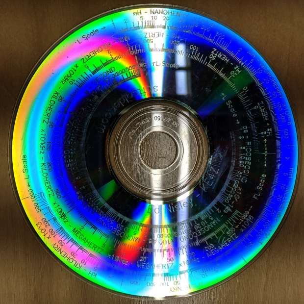
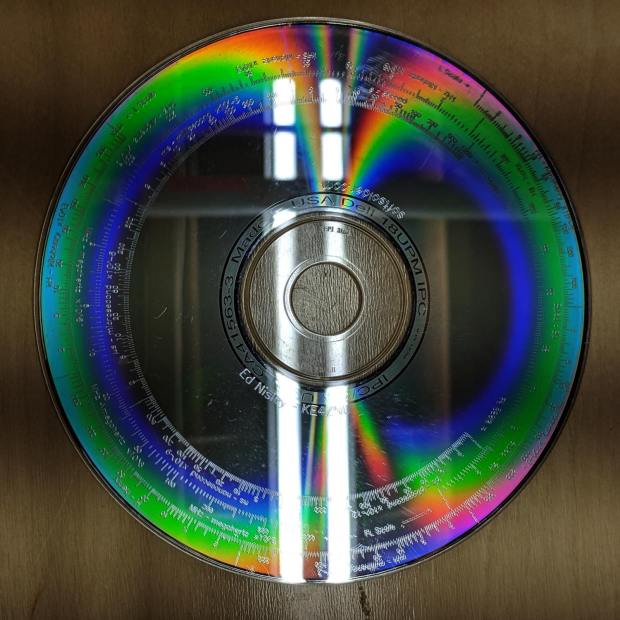
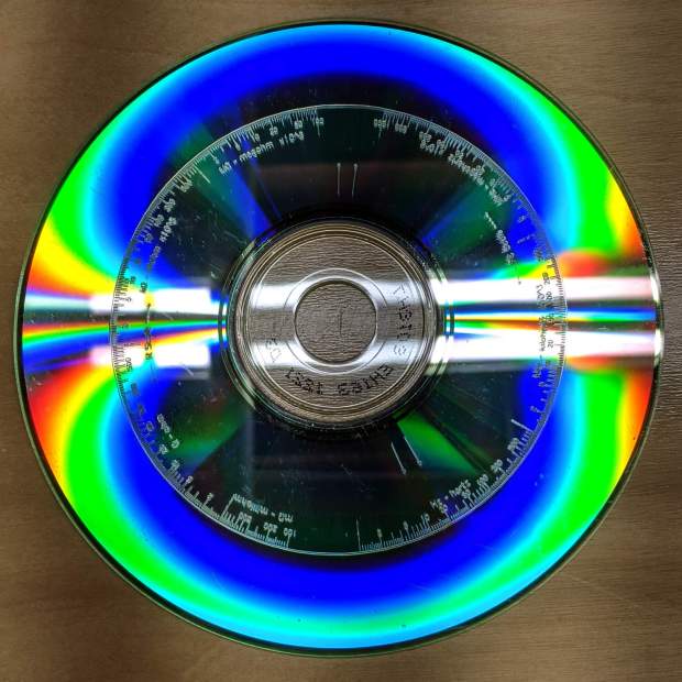
The tiny engravings don’t photograph well, because they’re floating atop the transparent disc and the rainbow patterns from the data layer, but they still come out OK even when scaled to fit on a hard drive platter:
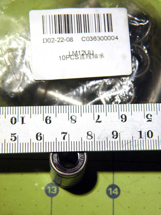
So I bought some LM12UU linear bearings from a nominally US-based eBay seller and received a suitably marked bag:
eBay – LM8UU bearings in LM12UU bag
They looked a bit on the skinny side:
eBay – LM8UU bearing
It seems somebody in the supply chain wasn’t paying attention, which isn’t surprising given the its ability to deliver ten hunks of reasonably precise machining to my mailbox for a buck-and-a-half apiece.
As it happens, I already have far too many LM8UU bearings and, after some unavailing back-and-forth with the seller, eBay customer service determined neither of us was “at fault” and refunded the whole order.
Being in no particular hurry, I ordered the next lot from halfway around the planet. Apparently, I’m now known throughout the land:
eBay – drop-ship addressing
Another label atop that one sported my actual address, with a matching Orange Connex tracking number barcode. Turns out OC is a “a joint venture between a leader in Chinese private equity investment, CITI CPE, and the a [sic] pioneer of global e-commerce platform, ebay”.
AFAICT, containers of “direct from China” packages arrive in the belly of a cargo airplane, get a sticker with their final destination, and enter the US postal system. It’s not clear buying from a “US seller” changes anything, as many of those packages come from addresses matching a building next to an airport.
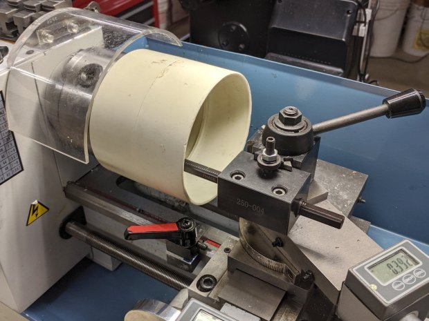
This came about while tinkering up a shade for a repurposed LED downlight:
PVC fitting – boring setup
It’s a 4 inch DWV pipe coupling I bored out to fit the LED housing, which was ever so slightly larger than the pipe OD.
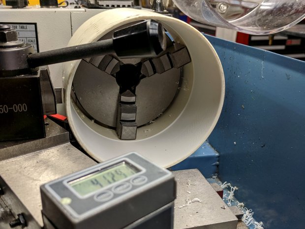
Cutting it off required as much workspace as the poor little lathe had:
PVC fitting – cutoff setup
Ignore the toolpost handle across the top. What’s important: the cutoff blade poking out of the QCTP, above the orange carriage stop lock lever, extending just far enough to cut through the coupling’s wall before the compound hits the coupling. The compound slide is all the way out against the cross-slide DRO, rotated at the only angle putting the tool where it needs to be and clearing the end of the coupling.
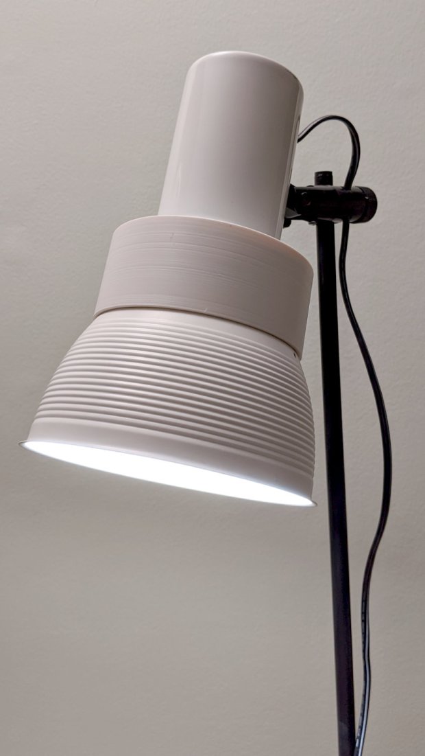
It ended reasonably well:
PVC fitting – LED floor lamp
But, in retrospect, was hideously bad practice. Next time, I’ll make a fixture to hold the fitting on a faceplate.