Ed Nisley's Blog: Shop notes, electronics, firmware, machinery, 3D printing, laser cuttery, and curiosities. Contents: 100% human thinking, 0% AI slop.
Using different card colors makes it easy to find your program deck in the Comp Center’s output bins:
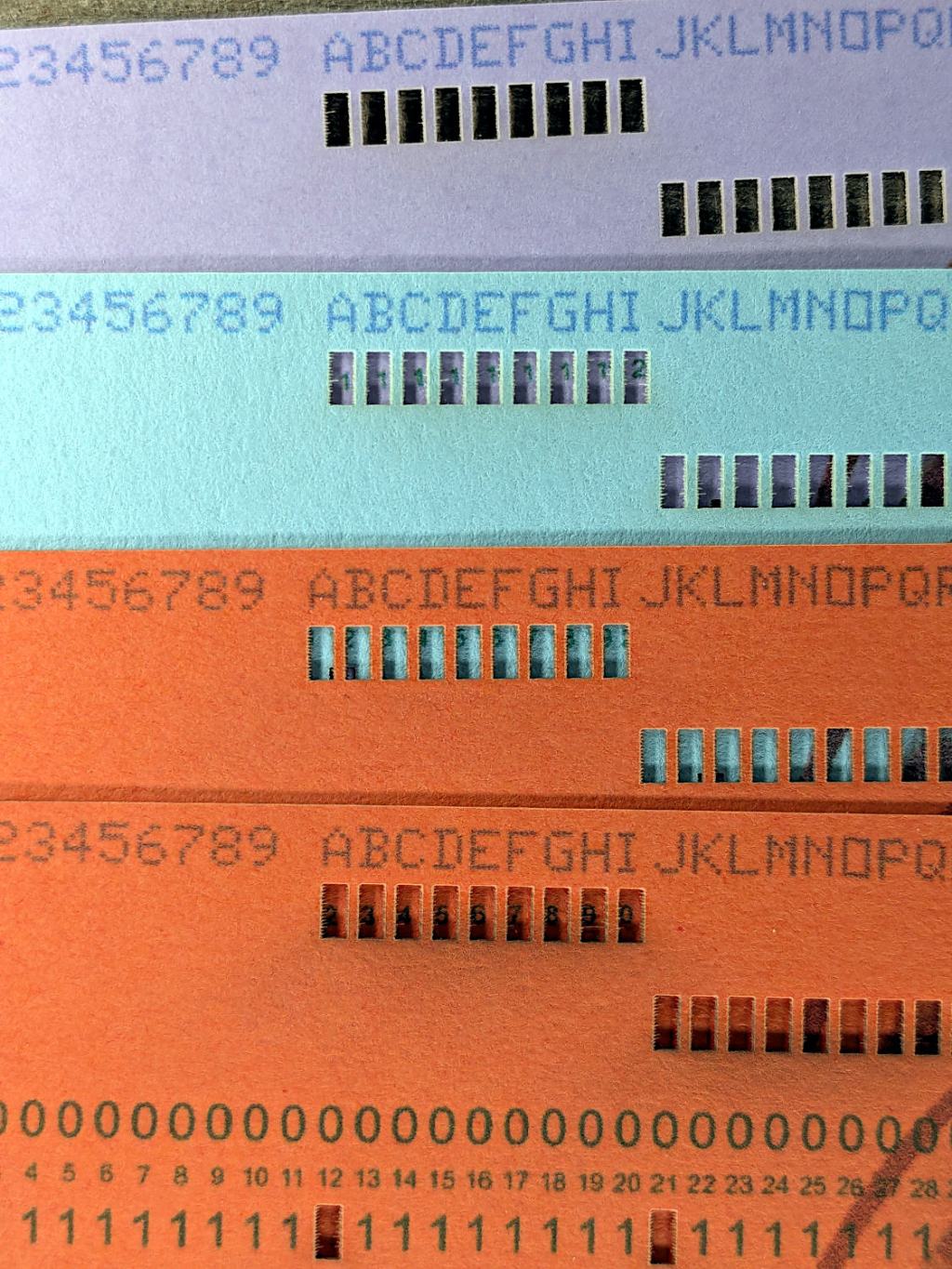
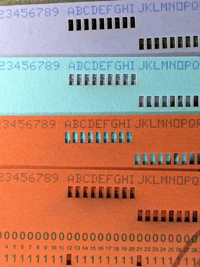
Punched Cards – paper color vs smoke stains
The smoke stains on the bottom orange card came from the same LightBurn settings used with the purple (violet?) and blue (teal?) cards: 400 mm/s, 35% power, and assist air enabled.
The conventional wisdom is that you *do not* use assist air while engraving, to avoid pushing the smoke / soot down onto the material, and I’ve generally followed that rule. Apparently evaporating holes in the other colors doesn’t generate much smoke and I had no reason to notice the air was enabled.
The upper orange card differs from the lower one only in having the assist air turned off, so I have definitely learned my lesson!
Readers of long memory will recall the dual-path assist air setup that pushes 2 l/m through the nozzle when the LightBurn layer has AIR disabled, specifically to keep smoke out of the nozzle and away from the lens; that gentle breeze doesn’t push smoke into the paper.
FWIW, that’s why I run a set of test cards before I do anything fancy for the first time.
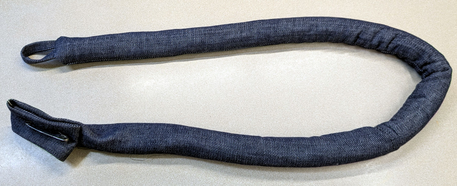
Mary made a frame weight to maintain tension on the fabric in the HQ Sixteen longarm:
Longarm fabric frame weight
It’s a sturdy cloth tube filled with BBs, somewhat like a grossly overweight door snake (a.k.a. draft stopper).
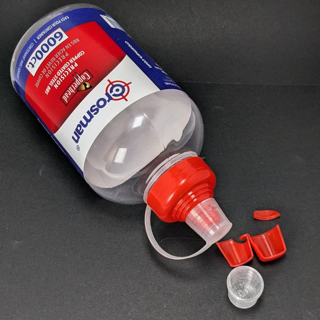
The bottle of 6000 copper-plated steel BBs arrived in an overwrap bag of the sort Amazon applies to all bottled products. This was a Good Thing, because the scrap of packing paper did nothing to cushion the bottle in an otherwise empty box. The bag contained most of the shattered cap and a few BBs, with escapees rattling around inside the box and surely a few left along the way.
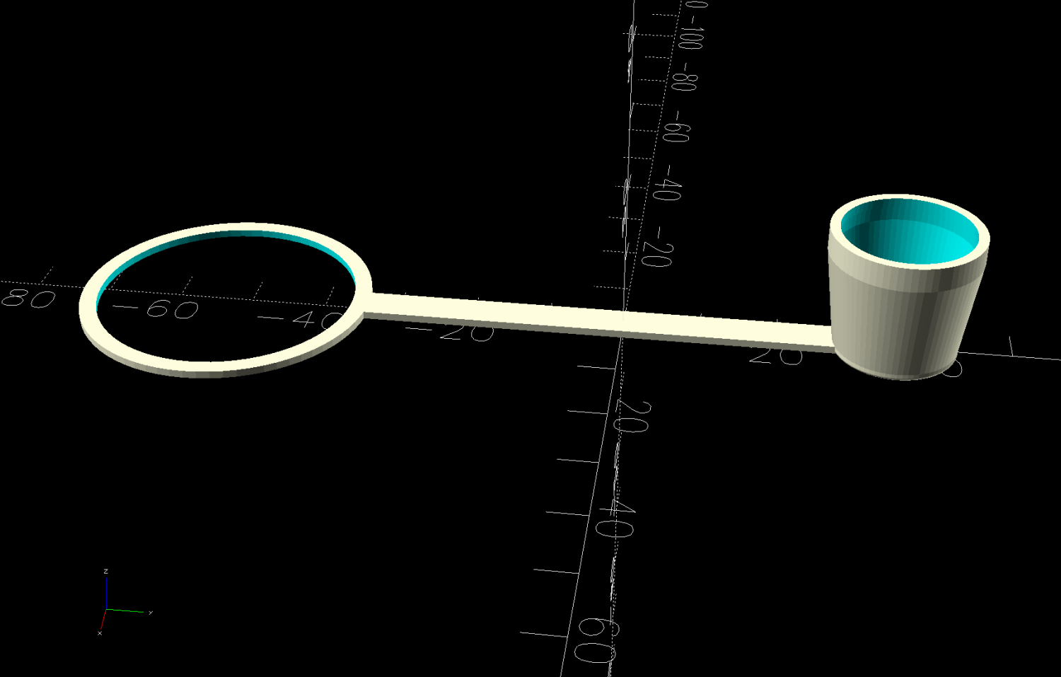
So I conjured a replacement cap from TPU:
Crosman BB bottle cap – solid model – build view
It fits around the bottle neck and snaps onto the spout just like the original:
Crosman BB bottle cap
Except this one is unbreakable.
The strapless TPU cap was a quick test to verify the fiddly shoulder snapping onto the bottle snout:
Crosman BB bottle cap – solid model – section view
As it turned out, we poured all 6000 BBs (minus those few lost-in-transit strays) into the cloth tube, but the bottle will come in handy for something someday.
This file contains hidden or bidirectional Unicode text that may be interpreted or compiled differently than what appears below. To review, open the file in an editor that reveals hidden Unicode characters.
Learn more about bidirectional Unicode characters
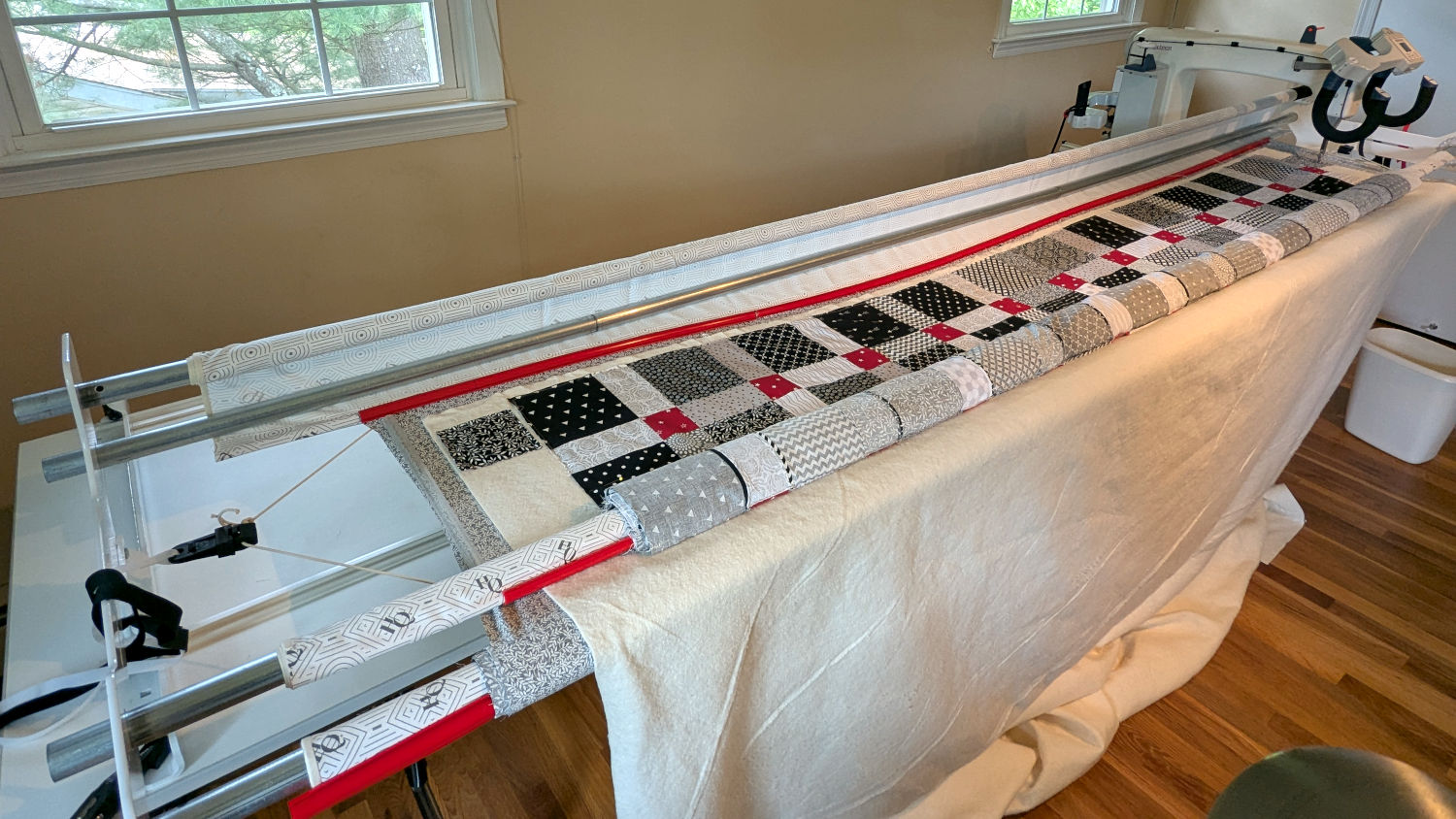
The rods (a.k.a. tubes or poles) holding & guiding the quilt top / batting / backing fabric on Mary’s HQ Sixteen longarm quilting machine span the eleven feet of the table:
HQ Sixteen – table overview
The two end plates are 1/4 inch steel plate with four punched holes for the rods / tubes, which look remarkably like EMT. The machine is two decades old and Mary is (at least) the third owner, so it’s no surprise the rods long ago wore through the white powder-coat paint on the plates and, during the course of a long quilting project, now deposit black dust on the table.
Black dust not being tolerable near a quilt-in-progress, Mary asked for an improvement.
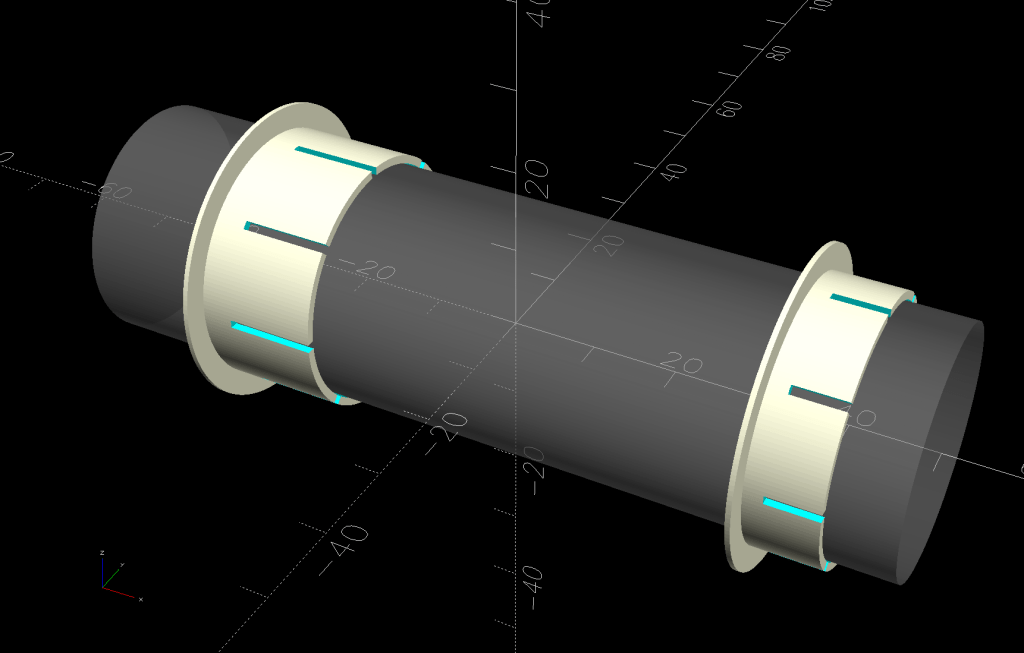
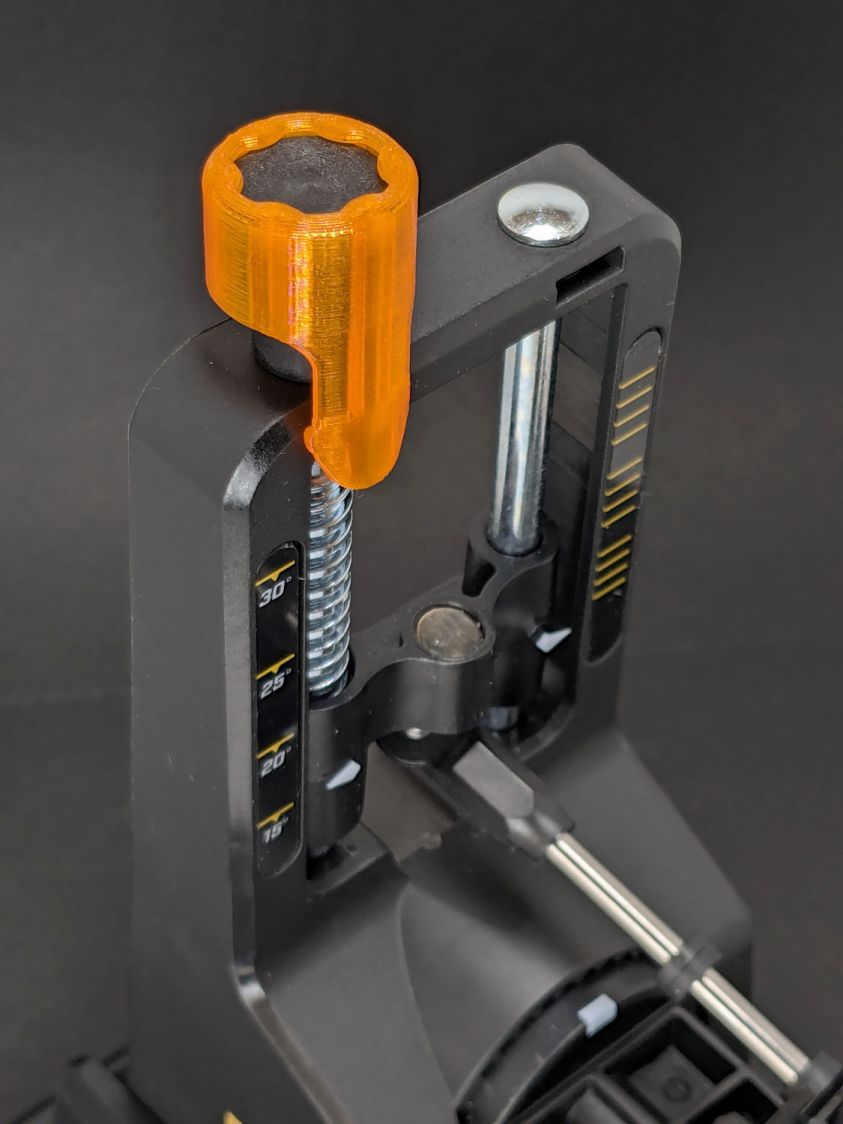
The tube OD is 28.7 mm (so it’s probably 1 inch EMT) and the plate hole ID is 31.2 mm (likely a scant 1-¼ inch punch), leaving barely a millimeter of clearance all around. I wanted to make a bearing from suitably slippery Delrin / acetal, but figured 3D printed PETG would suffice for at least while.
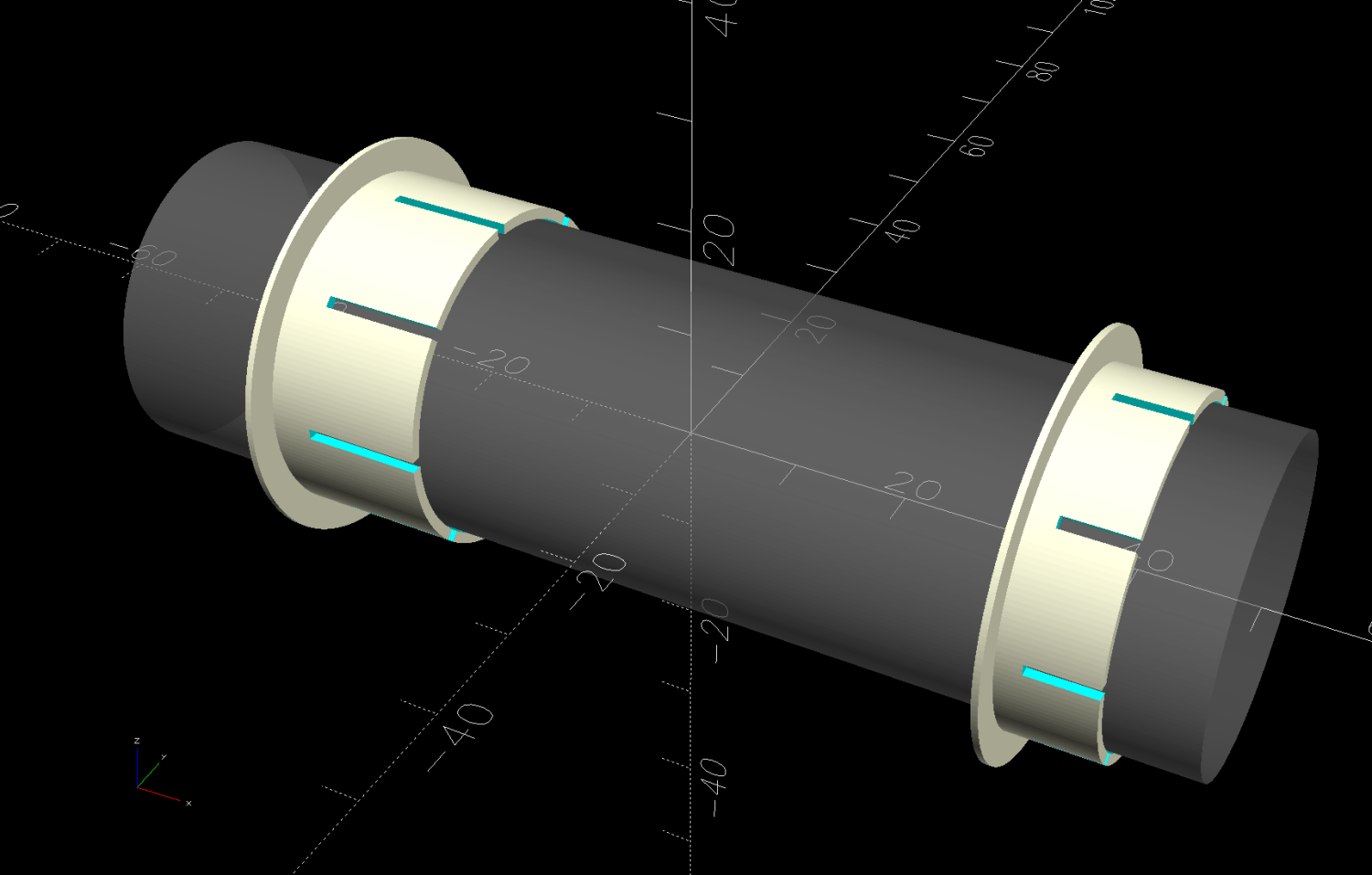
The proper term is “bushing“, because it has no moving parts:
Rod Bearing Sleeve – solid model – show view
On the right side, the bushing rim must fit between the sprockets and the plate:
HQ Sixteen rod – right front
The spring-loaded pin holding the tube in place (visible on the inside bottom) sets the maximum length:
HQ Sixteen rod – right outer
The left side has none of that, so I made the bushings a little longer:
HQ Sixteen rod – left inner
The left-side bushings will need a better design should normal back-and-forth sliding push them out of place.
A touch of silicone grease around the plate holes makes those bushings / bearings turn sooo smooth.
This file contains hidden or bidirectional Unicode text that may be interpreted or compiled differently than what appears below. To review, open the file in an editor that reveals hidden Unicode characters.
Learn more about bidirectional Unicode characters
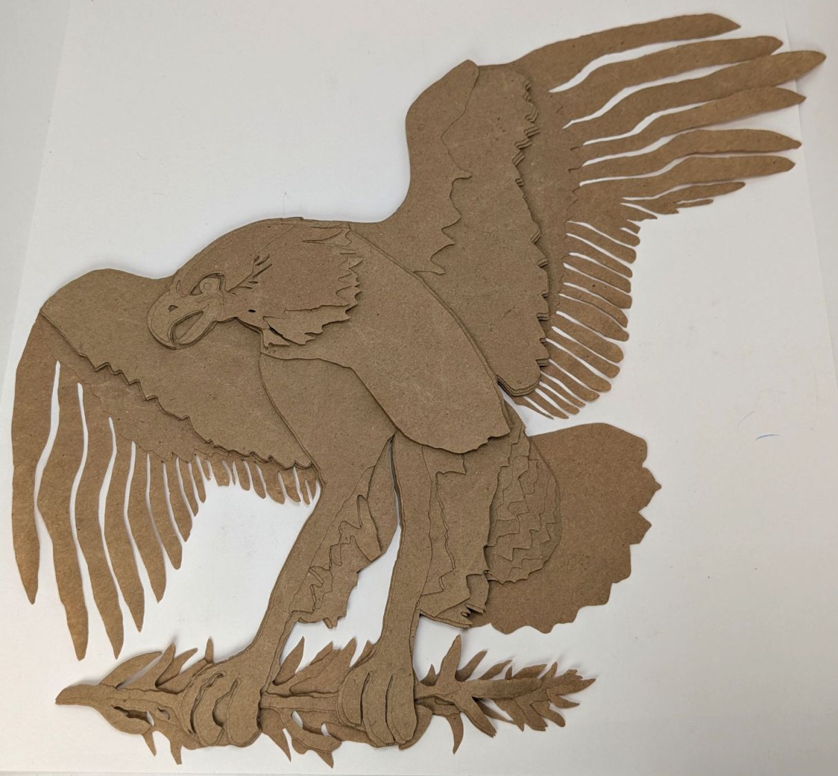
After considerable faffing, a few of the fifteen layers look like this in GIMP:
Apollo 11 Patch – eagle layers
Each layer is a connected white region defining the cut perimeter, which will expose some part of the layer(s) below it in the stack. The small squares in the corners provide a bounding box to make all the layers snap to the same location.
Put outlines on a cut layer, corner squares on a tool layer
Burn each layer separately
Testing the concept with packing paper looked surprisingly good:
Apollo 11 Eagle – layer test piece
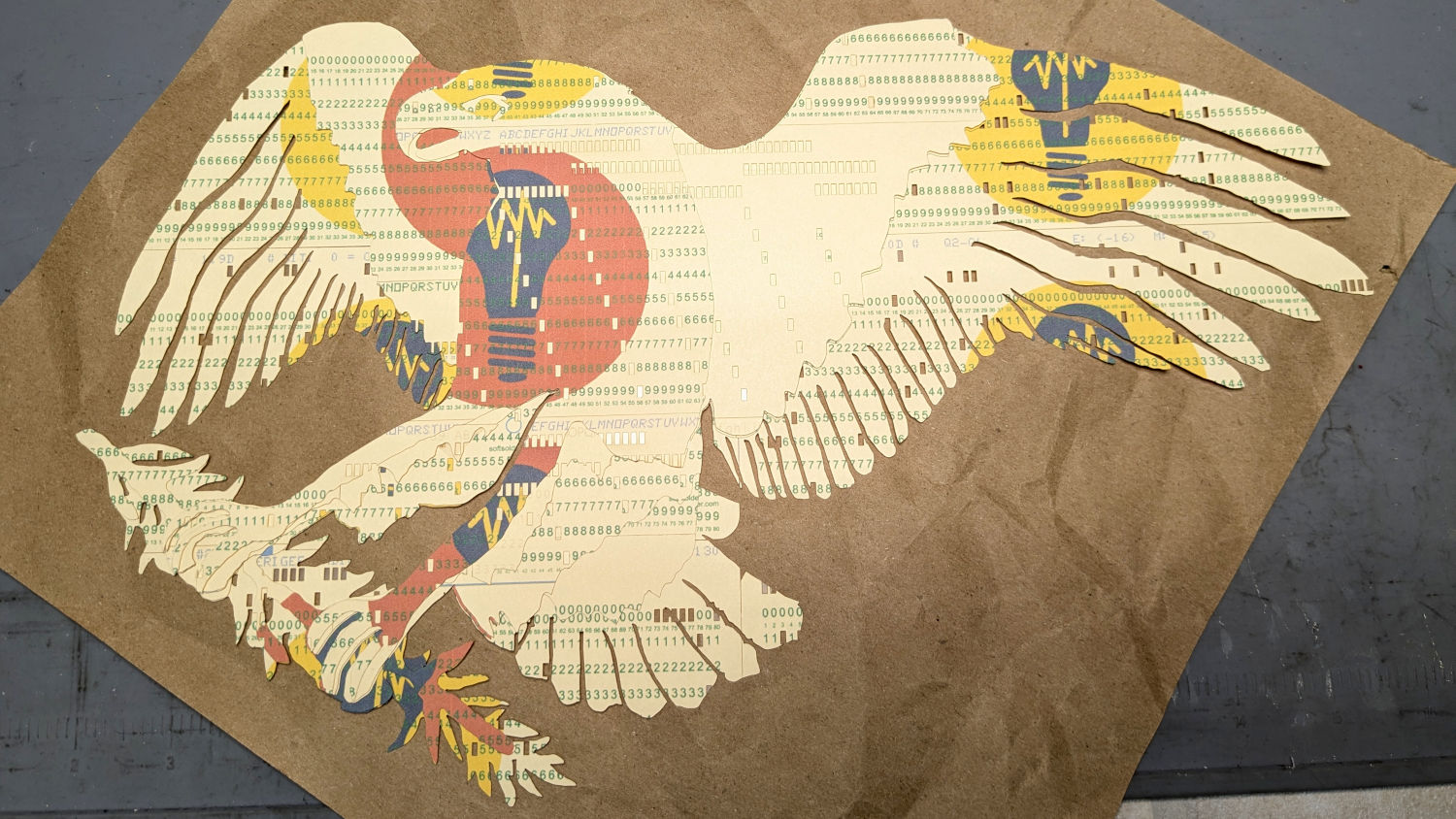
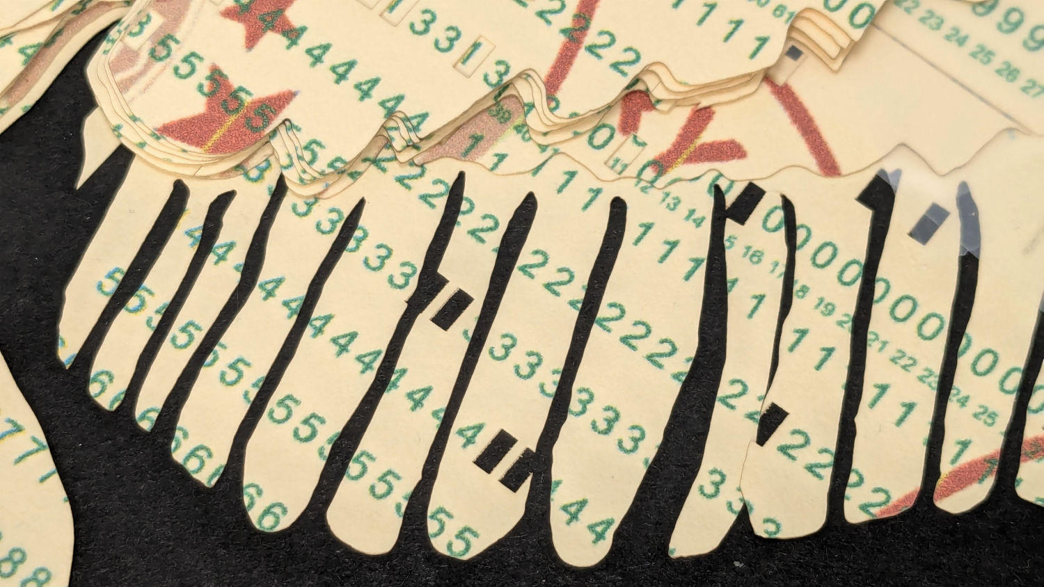
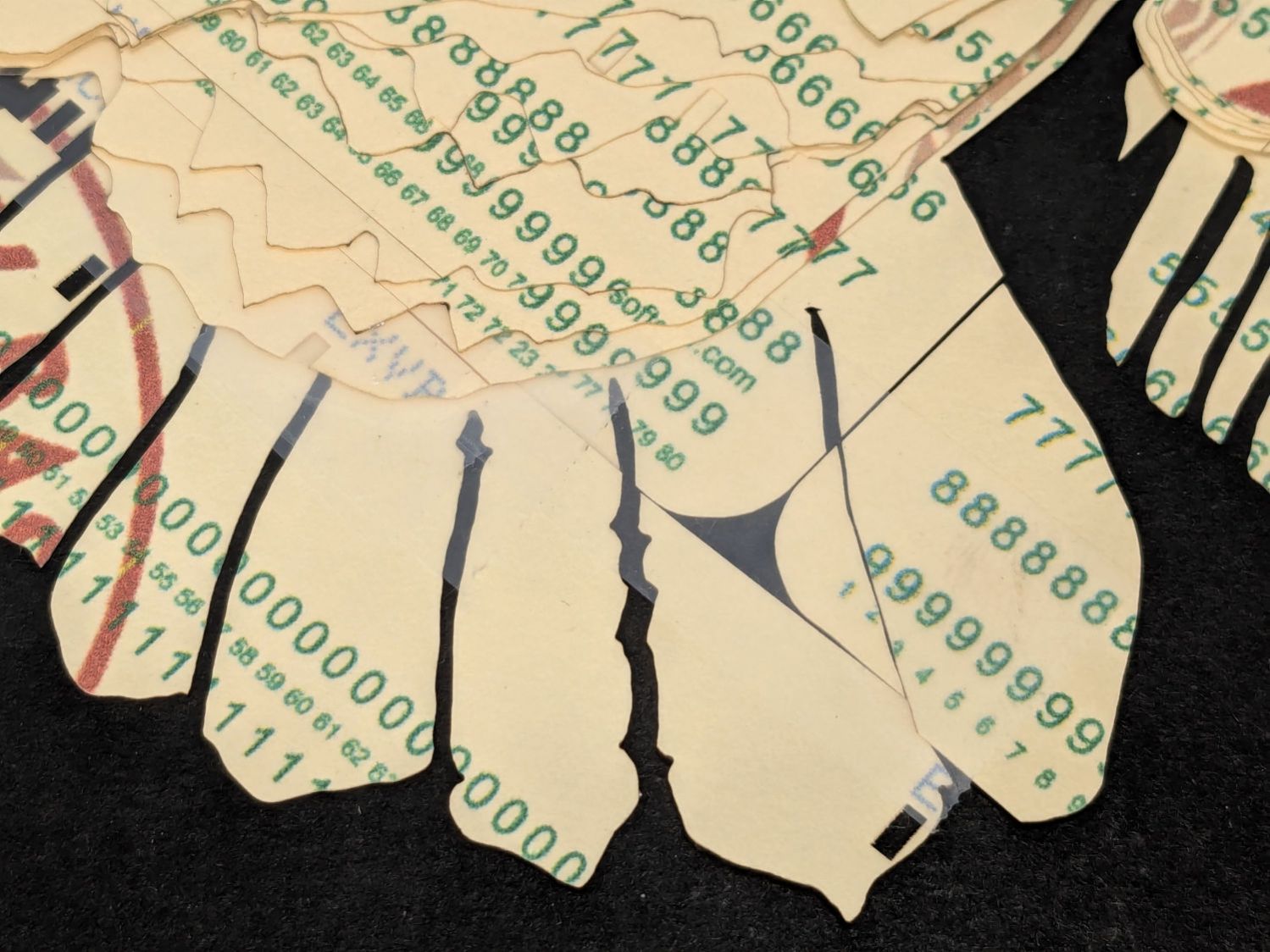
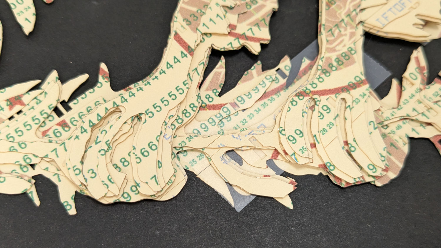
A few key layers on punched cards:
Apollo 11 Eagle – card partial test piece
The changes for each of those iterations required tweaking the original layer images to eliminate obvious-in-retrospect problems, recreating the SVG files, and importing into LightBurn. This is a relentlessly manual process.
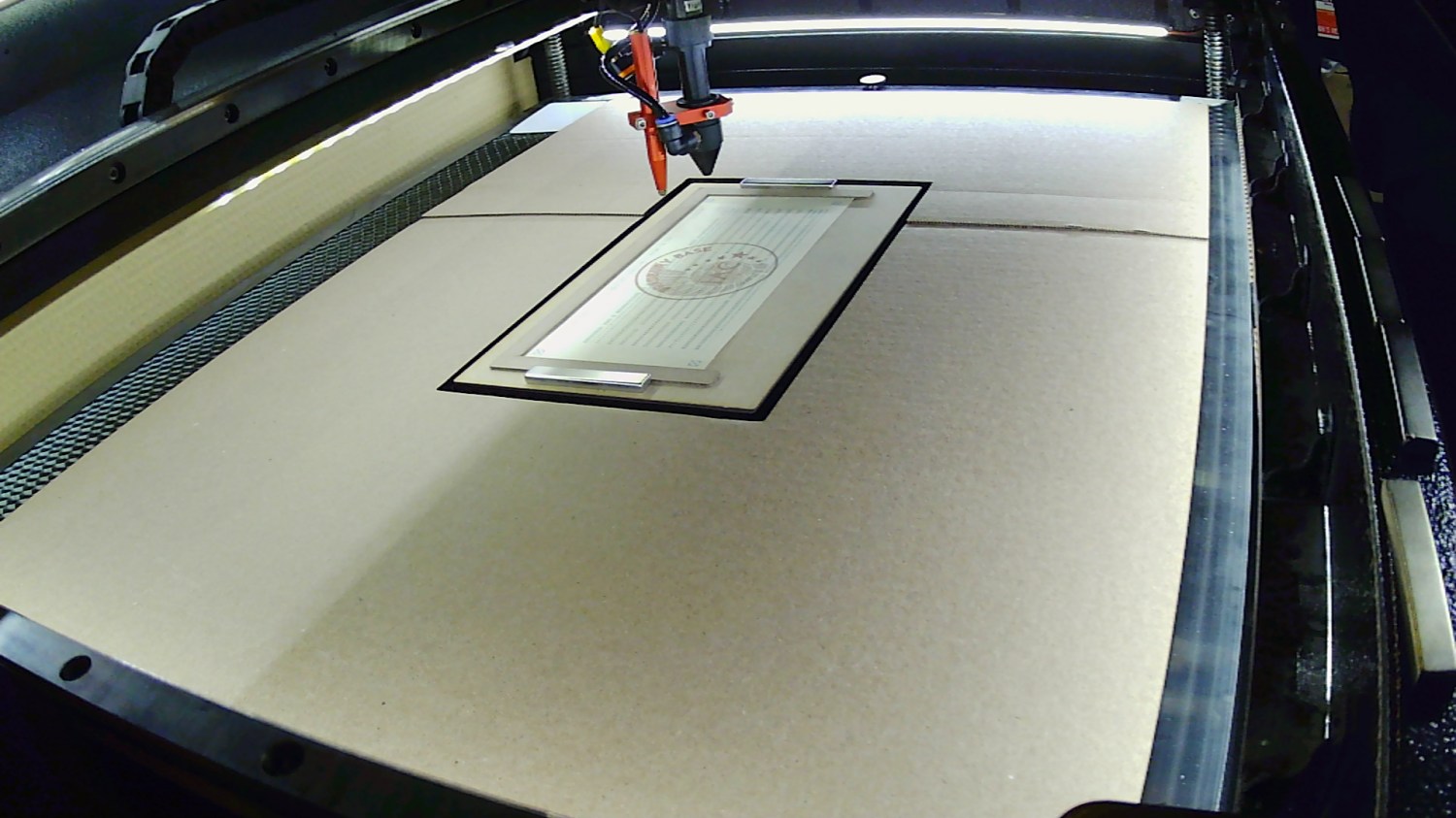
Then I ran a full-up test of all fifteen layers on cards punched with the Apollo source code.
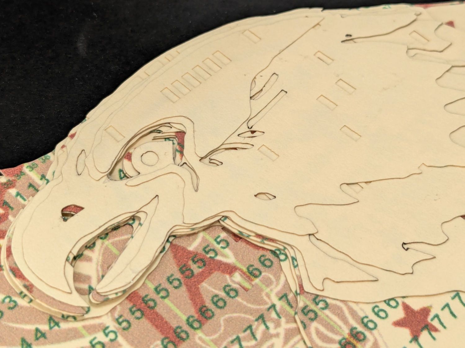
Cutting the head layers from face-down cards made them sufficiently white, although it’d be nice to have a different beak color and darker eyes :
Apollo 11 Eagle patch – layer test – head
I must arrange the cards with text to put more holes in the wings, although too many will cause fragile feathers:
Apollo 11 Eagle patch – layer test – wing
The white tail should be also done with face-down cards, more holes, and the three-way joint between the cards shifted under the tail layers to its left:
Apollo 11 Eagle patch – layer test – tail
The feet and olive branch were a total faceplant, as successive layers did not register accurately enough to overlay the leaves:
Apollo 11 Eagle patch – layer test – feet
Not to mention those ug-u-lee claws.
The wing layers need more rounding along their edges, perhaps with some thin cuts to emphasize the feathers.
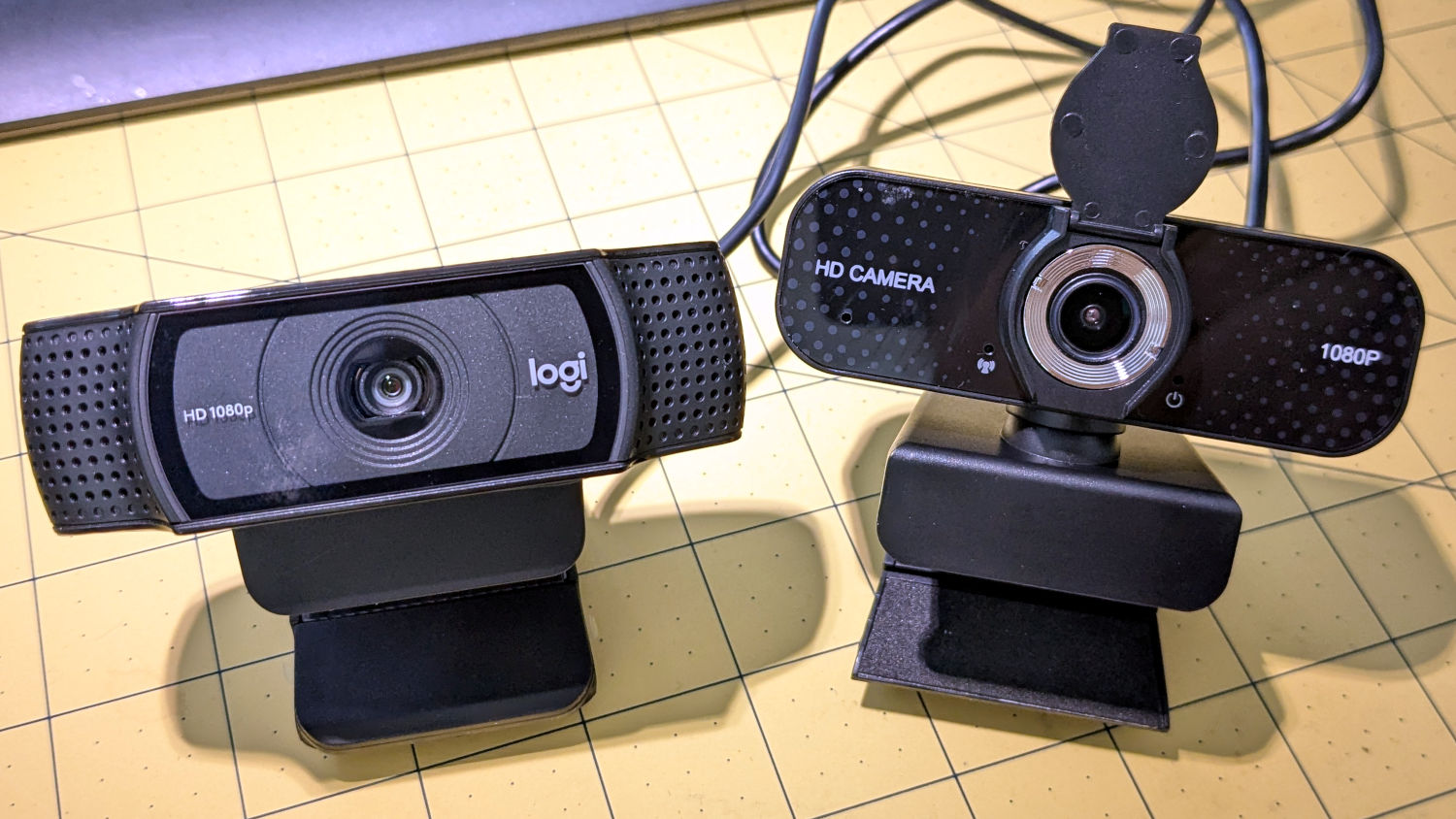
A brace of cheap HD USB cameras may improve the scenery around here during video meetings. They were $16, marked down from an absurd $130:
HD USB Camera price history
Some poor schlubs certainly dropped more than twice the price of a Genuine Logitech camera on these critters, but a nearly total lack of demand must have had some effect.
They do take their stylin’ cues from Logitech, although the speckled pattern on a shiny plastic sheet is amusing:
HD USB Camera – styling vs Logitech C920
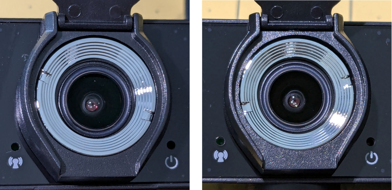
Unsurprisingly, the lens is fixed / manual focus. What looked like focus rings were in different positions on the two cameras:
HD USB Camera – lens focus notches
It turns out the rings were not glued in place, perhaps because they have absolutely no effect on the camera’s focus. Maybe there’s another camera model where they rotate the lens in a threaded socket, but this ain’t that.
The front panel has three pores:
A red Power LED is always on when it’s plugged in
A green On the air LED lights up when the camera is selected; I have no idea what the WiFi-ish glyph is supposed to represent
The “advanced noise canceling microphone” sits behind a pore offscreen left; the claim seems dubious.
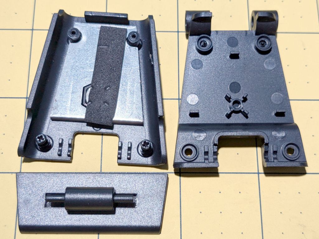
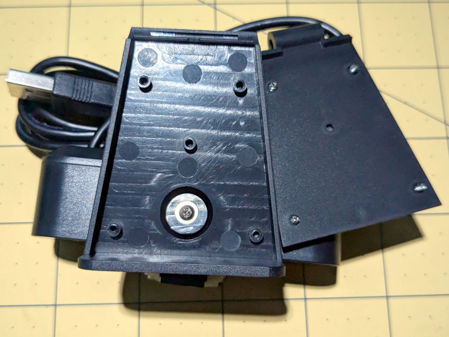
Because these may go into smaller spaces, I dismantled the base to see what was involved. Most of the screws lie underneath thin foam sheets:
HD USB Camera – ball mount interior
The lower plate has a tripod mount and a folding bracket:
HD USB Camera – baseplate interior
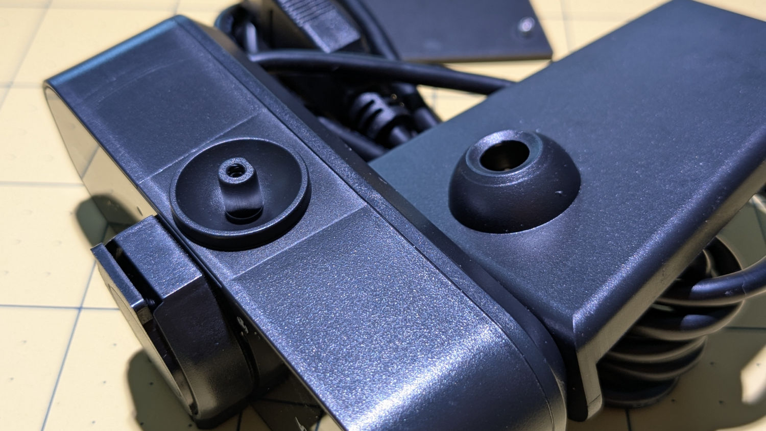
The camera body has a ball mount with a few degrees of movment:
HD USB Camera – ball mount detail
Reassembled and stuck inside the laser cabinet with some good double-sided foam tape, it definitely produces a better image than the previous camera:
Platform camera view
Whatever noise cancellation the mic may provide is irrelevant in there: nobody’s listening.
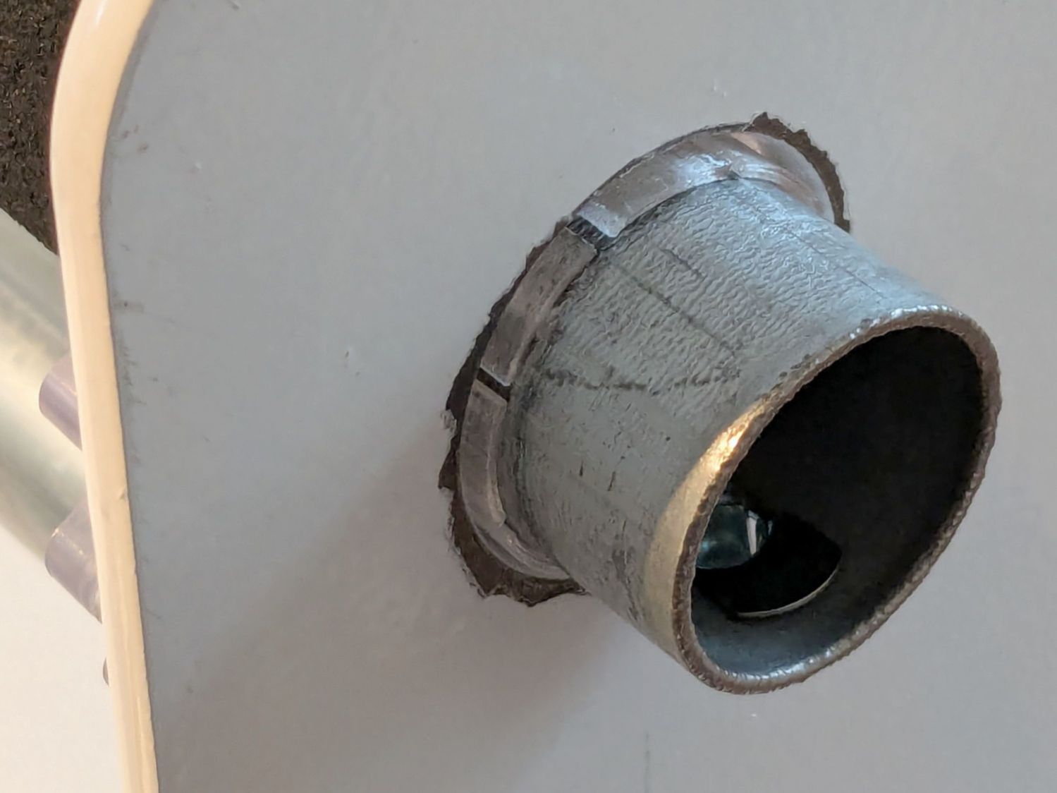
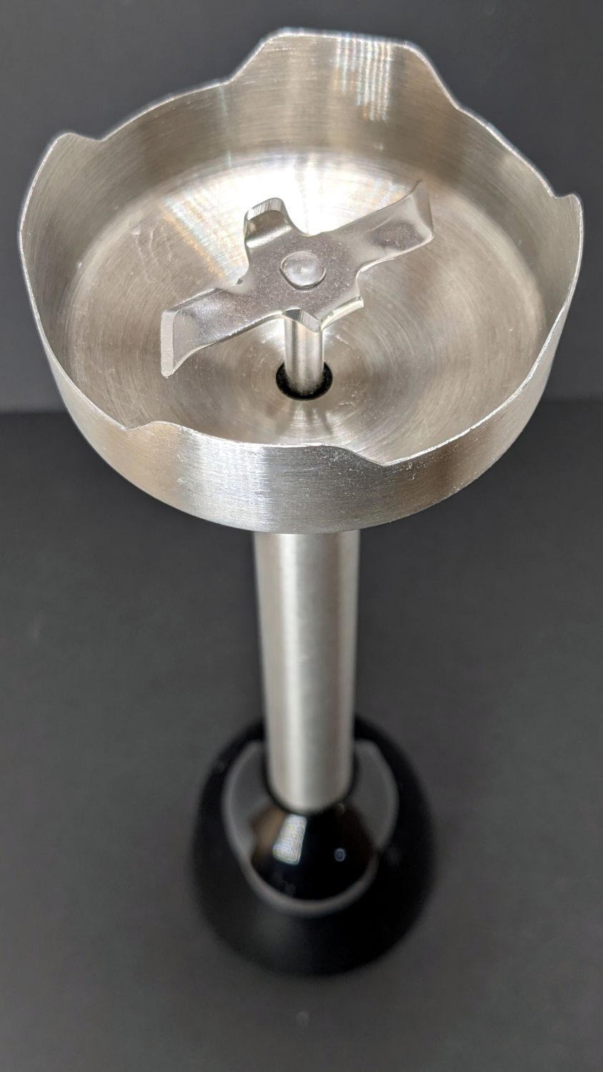
The business end of a cheap stick blender we bought a year ago to replace the previous stick blender (*):
Fresko stick blender
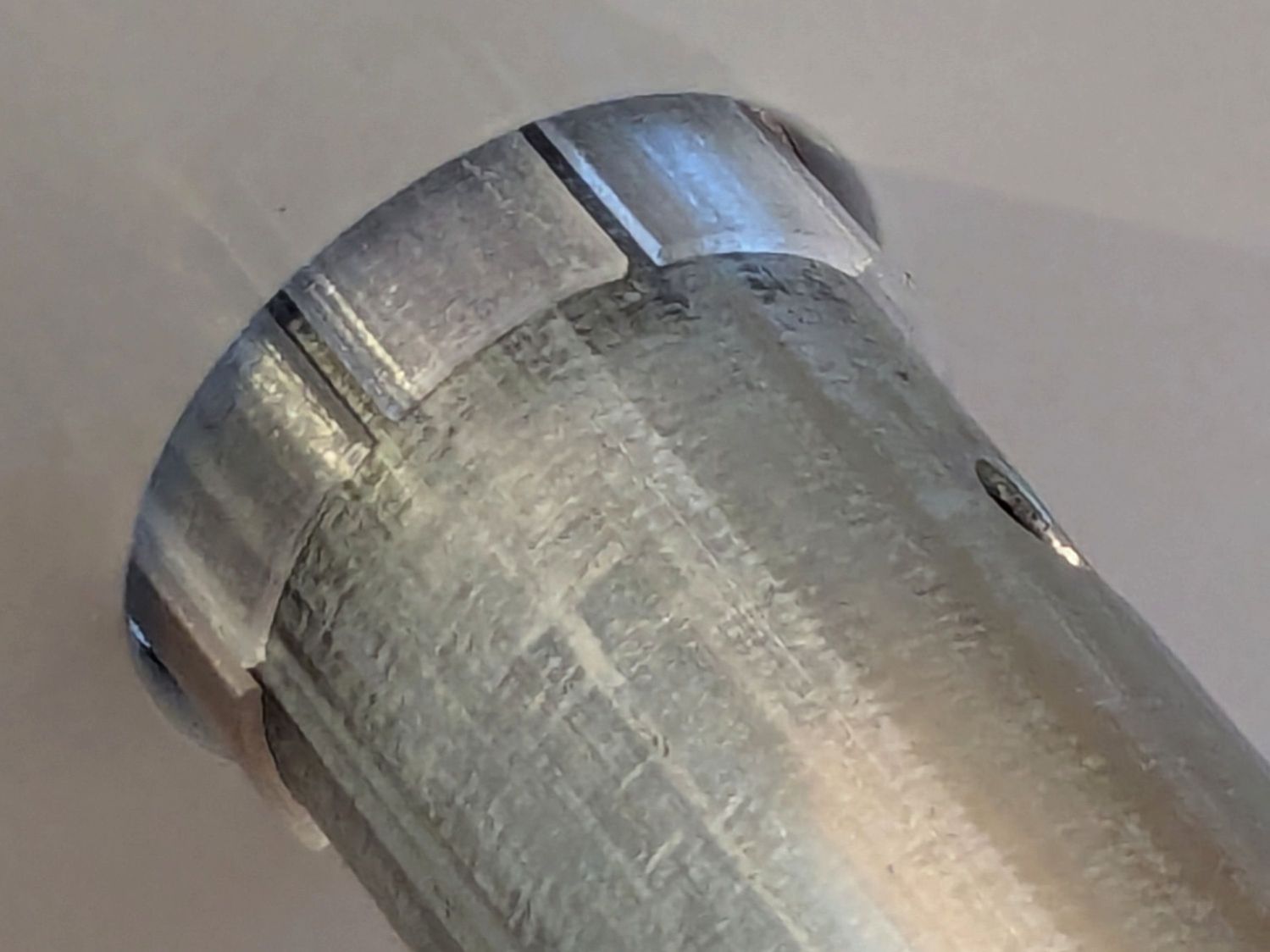
This one failed just slightly beyond the duration of its one-year warranty, apparently with one of the shaft bearings seized to the extent of making the blade un-turnable even by (carefully protected) finger force.
With nothing to lose (and a new blender inbound), it stood in the Basement Shop in that orientation for a week while I dripped penetrating oil around the shaft and wiggled the blade slightly back-and-forth. The bearing eventually broke free and the blade turned reluctantly.
Still having nothing to lose, I gave the shaft a few shots with a drift punch, moving it a few millimeters in each direction. This apparently disturbed the seized bearing just enough to let it turn less reluctantly, with more penetrating oil improving the situation.
Mixing a jar of water went well, even on high speed, but I doubt the bearing is in good health. We decided a blender with penetrating oil tucked up inside should be disqualified for food processing.
When it first locked up, I bought a significantly more expensive stick blender, knowing full well more money does not imply better design / better materials / more QC. This one is now designated as a Cold Backup blender for garden & shop use.
(*) For the record, my 3D printed shaft adapter failed while converting garden tomatoes into thick & zesty pizza sauce. I’m unsurprised PETG-CF wasn’t up to the task.