Ed Nisley's Blog: Shop notes, electronics, firmware, machinery, 3D printing, laser cuttery, and curiosities. Contents: 100% human thinking, 0% AI slop.
Nothing too challenging and, as nobody else ever sees this side of the lid, not very pretty:
Brita Pitcher – reinforced lid screws
I probably should have added a brass reinforcement strip around the cracked plastic mounts, but JB Weld epoxy should be strong enough for this job all by itself. Assuming, that is, it can maintain a grip on the plastic; I’m hoping the various fractures will lock it in place.
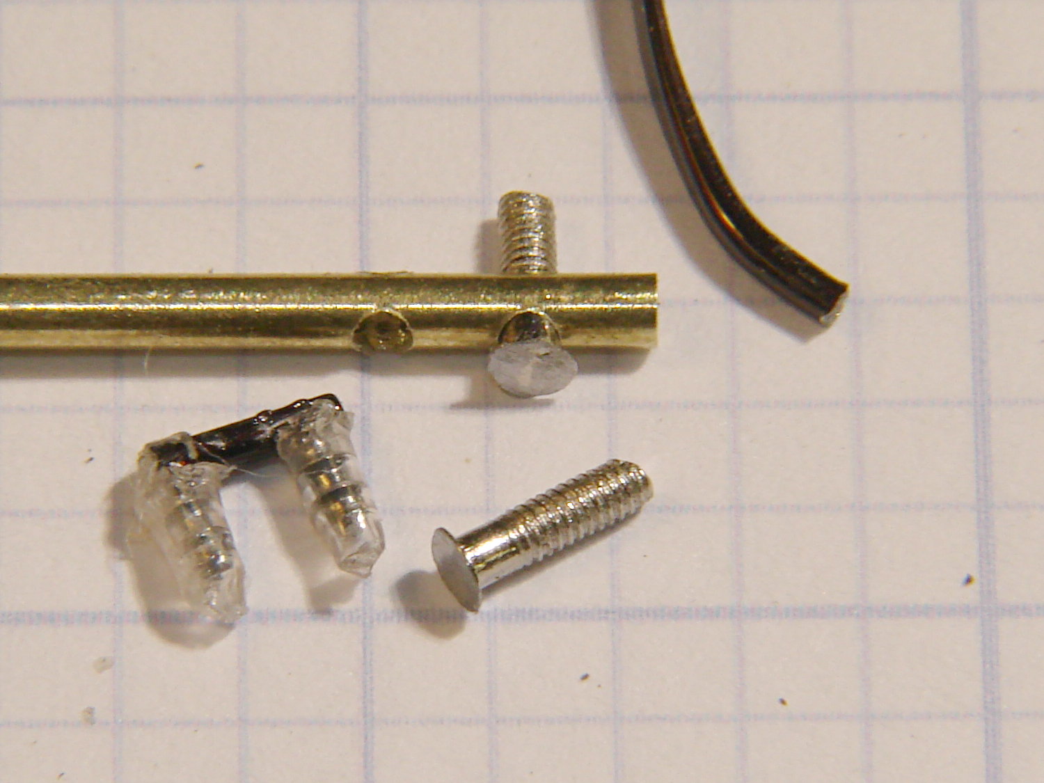
The left temple mount of Mary’s five-year-old and staggeringly expensive titanium Silhouette glasses snapped. Here’s the intact right earpiece and the broken piece from the left temple (the lens is upside-down on the paper):
Silhouette frame – broken temple part
They’re just about ideal glasses, with nothing more than two lenses and three metal bits, but that means simple repairs don’t come easily. The Official Repair Price was about $120 to install a whole new earpiece, so, seeing as how she had these customized for computer work and wouldn’t be wearing them when anybody else was around, I got the job…
First off, mask the lenses with Parafilm to avoid scuffs:
Silhouette glasses – lens protection
Then cut out the broken part shown in the first picture. It’s attached to the lens with a U-shaped bit of transparent plastic that fits into the frame holes and captures its two peg legs; I used flush-cutting pliers to carve away the plastic bar on the inside of the lens.
The lens mount fragment is flat-out not reparable, but the broken end of the earpiece lies flush against the lens and is roughly circular. Even better, a 1/16 inch brass tube from the Little Box o’ Cutoffs fit the temple end perfectly: OD = 62 mils, ID = 35 mils.
The Little Box o’ Tiny Screws produced a pair of stainless steel screws (intended for the hinges in ordinary eyeglass temples) that also fit the holes in the lens and were precisely the right length, so the overall plan came together. The screws seem a bit over 1 mm diameter and I don’t have a nut for them, but epoxy is my co-pilot…
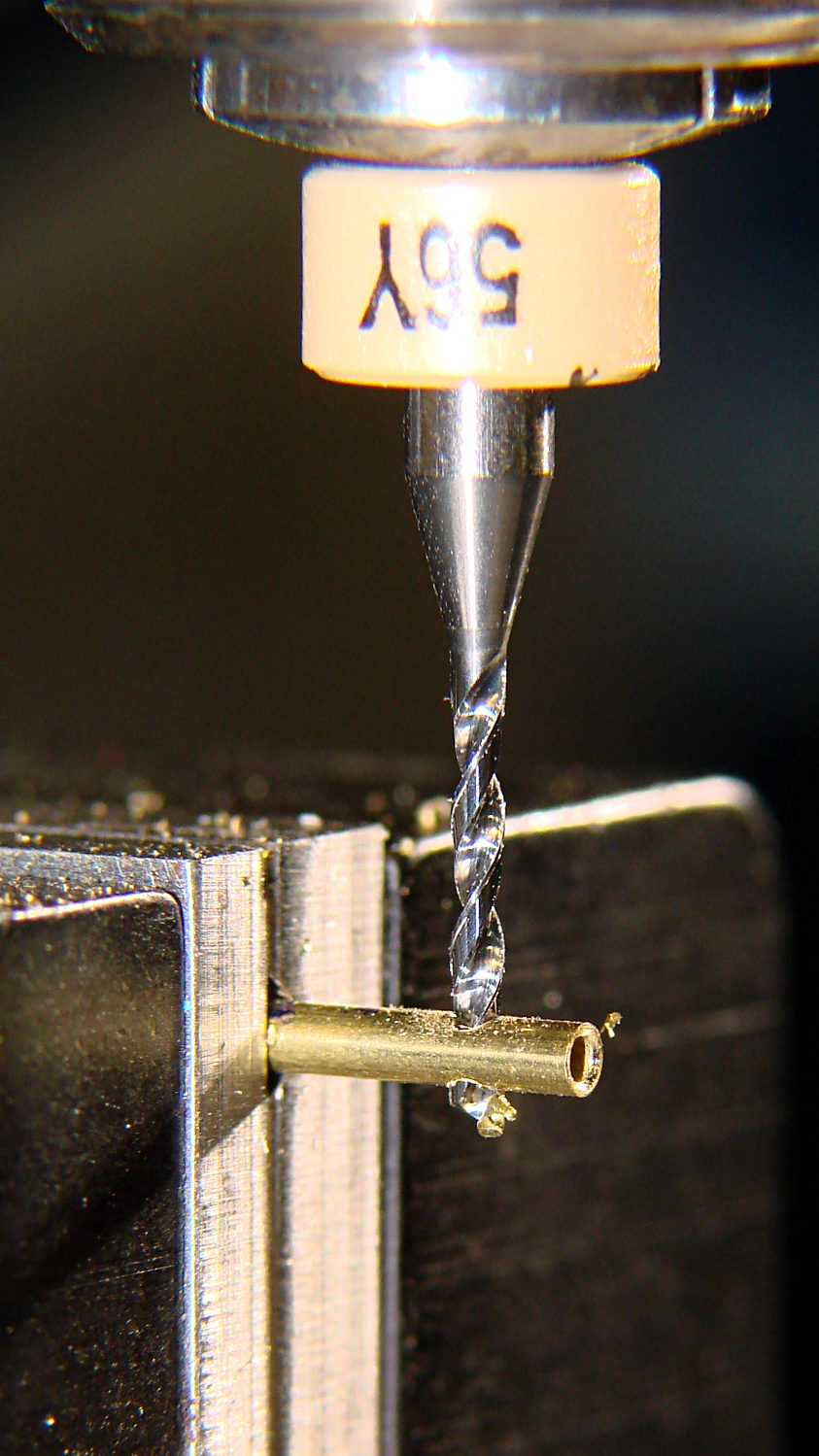
Line up and drill a pair of 47 mil clearance holes in that piece of 62 mil OD brass tubing, leaving barely 7 mil behind on each side:
Drilling brass tube
I may have to frame that picture…
Much to my astonishment, drilling those two holes worked on the first try. I’d chamfered the end with a #1 center drill while mulling over how all this would work out.
File off the screw heads to leave a thin plate:
Silhouette frame – temple mount parts
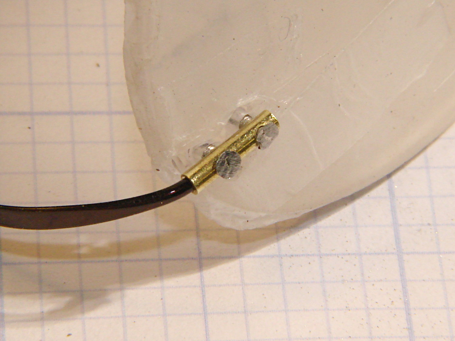
A dry fit shows how everything hangs together:
Silhouette frame – temple trial fit
The intact earpiece holds the lens at the proper angle on a flat surface, so as long as I can keep the repair parts in place on the lens, the temple angle will take care of itself.
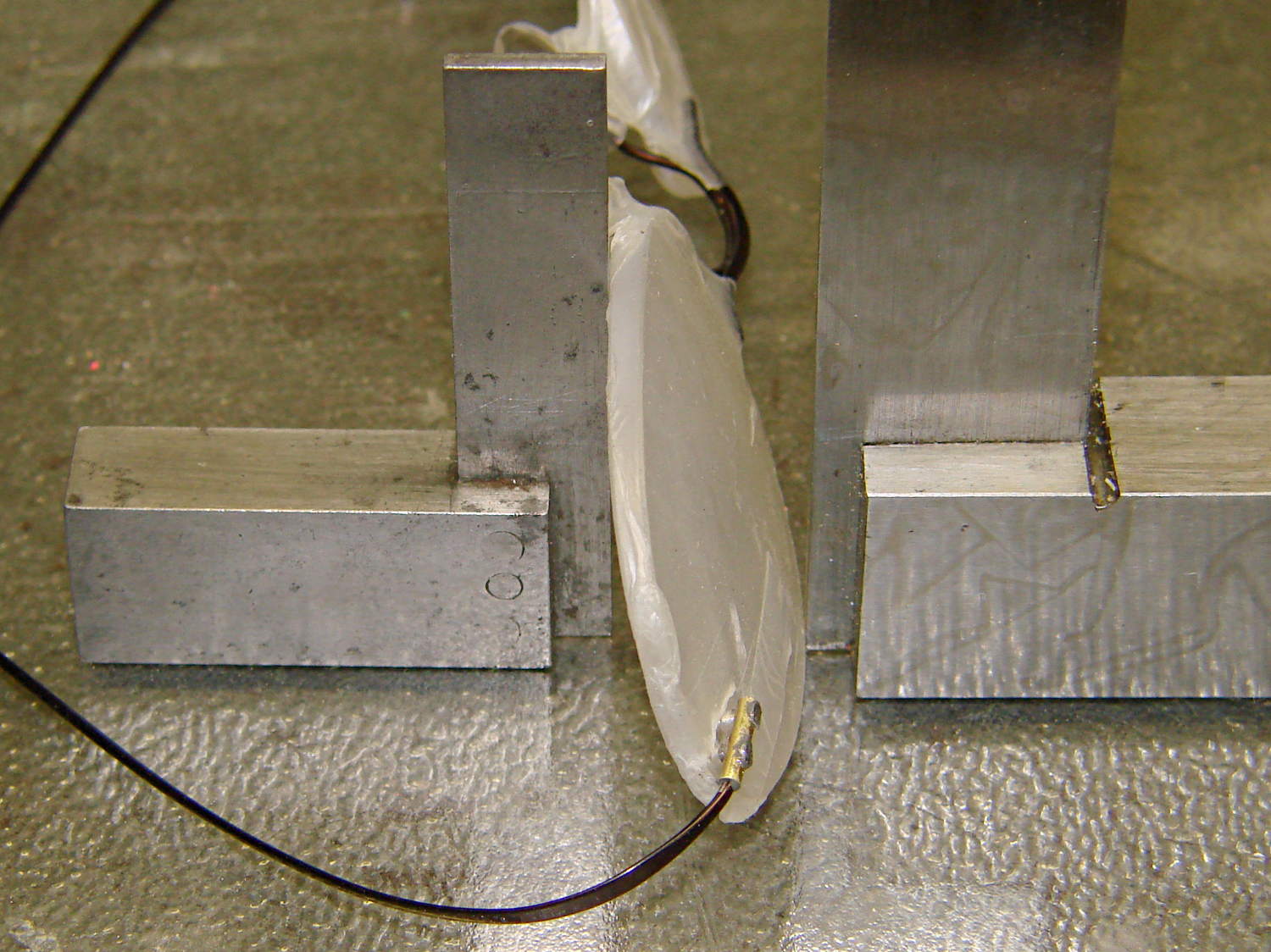
I scuffed up the broken end of the earpiece to encourage a good epoxy bond, bent the edges of those flat plates around the tube, and cleaned everything with acetone. Tiny dabs of JB Weld epoxy hold the screws and the temple piece in the tube, with those little machinist’s squares encouraging the lenses to stay put:
Silhouette frame – mount curing
A day later, lay the lenses face down so the screws point straight up and dab on more JB Weld:
Silhouette frame – lens mount curing
Those dots aren’t quite as round as I’d like, but they’re the better part of 2 mm OD and I’m not complaining much. Note the nice fillet around the temple piece at end of the tubing.
Pause another day for curing…
Then file off the rough edges and peel off the Parafilm. It’s a bit on the garish side, but Mary preferred the Steampunk look over a crude paint job, particularly because it’s invisible from her side of the lens:
The HRECOS folks installed a display on the Walkway Over the Hudson that shows current environmental conditions at the river sampling station just north of the bridge:
HRECOS Display with internal condensation
Those two blurry white rectangles are paper charts taped to the inside of the case below the scrolling LED display, so I think they’re discovering what happens when you trap ambient air inside a sealed enclosure without dehumidification. Even if they weren’t opening the case every now and again to change the charts, diurnal pumping would pull outside air past any affordable non-hermetic seal.
That fancy electronics won’t last long under those conditions; I foresee several pounds of silica gel in their future…
The whole point of the new guide tube block is to see if a larger ID tube will reduce the force required to pull the filament through it; long after Dan suggested simply using a larger tube, I got around to picking up a lifetime supply of 1/4 inch OD polyethylene tubing: 25 feet for $3. The ID is about 0.17 inch = 4.3 mm, large enough to let the 1.75 mm filament move smoothly, and the inside clearance provides a few millimeters of free motion so that retraction moves don’t require pushing the guide tube around.
The new filament guide + wire cover anchors the spool end of the tube:
M2 Larger Filament Guide – overview
On the other end, I blobbed a piece of 1/4 inch ID tubing to anchor the guide tube. It’s nicer than the twist of cardboard I used before, but nothing to get excited about:
As I hoped, the larger guide tube reduces the force required to pull the filament into the extruder under 1 pound. Most of that force comes from persuading the filament spool to drag-rotate around the plastic support arm, so some simple improvements should help there, as well. I foresee some bearings in its future.
Fine tuning of the tubing length is also in order, but that’ll require more printing sessions.
With the reverse-engineered wire cover model in hand, a bit of tinkering extends one side into a relentlessly rectangular block with a hole for the filament guide tube:
M2 Wire Cover Filament Guide – overview
Because the block sits somewhat to the rear of the spool, I added a conical entrance to help ease the filament around the corner into the tube. The hole fits the larger 1/4 inch tube that I’m trying out, with a stop equal to the tube’s 0.17 inch ID just before the conical section, as shown in this cross-section view:
M2 Wire Cover Filament Guide – guide tube section
It fits just about the way you’d expect:
M2 Larger Filament Guide – rear view
The perspective makes the guide tube look more angled than it really is; most of that curve is toward the front, so it’s considerably foreshortened in this view.
The metal bar with the cross pin sticking up in front is a bar clamp that holds an oak strip across the back of the bench to keep the M2 from walking away.
The OpenSCAD source code:
// Improved M2 filament guide and X-min switch wire guide
// Ed Nisley KE4ZNU - Oct 2013

Layout = "Build";				// Build Section

//- Useful Stuff

function IntegerMultiple(Size,Unit) = Unit * ceil(Size / Unit);

Protrusion = 0.1;

HoleWindage = 0.2;

//- Sizes

PlateMinThick = 8.0;				// basic thickness excluding wire guides
PlateLength = 55.0;					// from side of frame beyond top wire guide

TopGuideLength = 7.0;				// protrusion from plate

PlateThick = PlateMinThick + TopGuideLength;

echo(str("Total thickness: ",PlateThick));

GuideTubeOD = 6.3;					// max diameter!
GuideTubeID = 4.3;					// max diameter!
GuideTubeOffset = 45.0;				// centerline from edge of frame

//- Adjust hole diameter to make the size come out right

module PolyCyl(Dia,Height,ForceSides=0) {			// based on nophead's polyholes

  Sides = (ForceSides != 0) ? ForceSides : (ceil(Dia) + 2);

  FixDia = Dia / cos(180/Sides);

  cylinder(r=(FixDia + HoleWindage)/2,h=Height,$fn=Sides);
}

//- Put peg grid on build surface

module ShowPegGrid(Space = 10.0,Size = 1.0) {

  RangeX = floor(100 / Space);
  RangeY = floor(125 / Space);

	for (x=[-RangeX:RangeX])
	  for (y=[-RangeY:RangeY])
		translate([x*Space,y*Space,Size/2])
		  %cube(Size,center=true);

}

//- Define basic block shape
//  Mostly reverse engineered from
//    https://github.com/MakerGear/M2/blob/master/Printed%20Parts/STL/M2%20X%20Endstop%20Wire%20Cover%20with%20Filament%20Guide.stl
//	Hence all the magic numbers...

module BaseBlock() {

SideGuideLength = 4.0;				// protrusion = even with frame interior
ChannelDepth = 4.5;					// wiring channel
FrameOffset = 28;

	translate([18,28,0]) {			// align neatly for later processing

		if (true)
			color("Green",0.2)
				translate([-18,22,15])
					rotate([-90,0,-90])
						import("file:///mnt/bulkdata/Project%20Files/Thing-O-Matic/M2%20Parts/Filament%20Guide/M2+X+Endstop+Wire+Cover+with+Filament+Guide.stl",
								convexity=10);

		difference() {
			linear_extrude(height=PlateThick,convexity=5)		// main block
				polygon(points=[[0,0],[0,22],[12,22],[12,7.5],[22,7.5],
								[22,-(PlateLength + FrameOffset)],[-18,-(PlateLength + FrameOffset)],
								[-18,0]
						]);

			for (i=[-1,0])
				translate([17,((i*15.0)+ 1.05),-Protrusion])
					rotate(180/6) {
						PolyCyl(3.1,(PlateMinThick + 2*Protrusion),6);		// screw holes
						PolyCyl(5.7,(3.0 + Protrusion),6);					//  ... countersink
					}

			translate([0,0,(PlateMinThick - ChannelDepth)])		// wire channel
				linear_extrude(height=15,convexity=5)
					polygon(points=[[2,-5],[2,19],[10,19],[10,-22],[-15,-22],[-15,-5]
							]);

			translate([-10,14,PlateMinThick])				// M2 frame
				rotate(-90)
					cube([42,35,10],center=false);

			translate([-5,5,(PlateMinThick + SideGuideLength)])	// shorten side guide
				cube([20,20,10],center="false");
		}
	}
}

//- Complete object

module GuideCover() {

	difference() {
		BaseBlock();

		translate([50,-GuideTubeOffset,PlateThick/2])
			rotate([0,-90,0])
				rotate(180/6)
					PolyCyl(GuideTubeID,60,6);

		translate([25,-GuideTubeOffset,PlateThick/2])
			rotate([0,-90,0])
				rotate(180/6)
					PolyCyl(GuideTubeOD,60,6);

		translate([41,-GuideTubeOffset,PlateThick/2])
			rotate([0,-90,0])
				rotate(180/6)
					cylinder(r1= 0.5*PlateThick,r2=GuideTubeID/2,h=8,$fn=12);
	}
}

//- Build it

ShowPegGrid();

if (Layout == "Section")
	difference() {
		GuideCover();
		translate([2*100/3,-GuideTubeOffset,-PlateThick])
			rotate(180)
				cube([100,PlateLength,3*PlateThick]);
	}

if (Layout == "Build")
	GuideCover();
The Makergear M2 comes with a plastic block that covers the X-min switch wiring and anchors the end of the filament guide. Because the guide wasn’t anchored to the block, bumping the guide tended to bend the filament where it exited the block. To prevent that, I hot-melt-glued the guide to the block, which really wasn’t particularly elegant. This picture shows the X-min switch relocated to contact the platform, with the slightly out of focus blob anchoring the guide off to the right:
M2 – Z-min switch at rear X gantry
Makergear provides STL files of the M2’s printable bits, including several versions of the wire cover block. This corresponds to the one on my M2, although the rounded edges don’t come through in the plastic very welll:
Stock M2 Wire Cover Filament Guide – solid model
Because STL files aren’t editable, I reverse-engineered the dimensions into an OpenSCAD model that I could use as the basis for a different guide. This is just the basic wire cover, minus the filament guide extension, plus a flat end that wraps around the edge of the chassis:
M2 Wire Cover – reverse engineered
The trick is to import the STL into OpenSCAD, then build a model that matches the key dimensions. Fortunately, Makergear used hard metric sizes for everything, so most of the numbers came out as integers or single-place decimals:
The shimmer indicates coincident surfaces; that’s ordinarily a Very Bad Thing, but in this case it shows that the dimensions match. The top of the holes have neat hexagonal patterns where my straight-sided PolyHoles extend through their chamfered circular holes:
Unlike my from-scratch OpenSCAD models, this one bristles with magic numbers that describe the dimensions of the M2 STL model. The basic shape comes from an extruded polygon matching the outside walls, another extruded polygon knocking out the wire channel, then cubes lopping off the top surfaces:
M2 Wire Cover Filament Guide – overlay – F12 view
The end result of all that thrashing around has a certain Soviet Concrete look to it:
M2 Wire Cover – OpenSCAD solid model
This version lacks the filament guide; I wanted to make sure all the protrusions and channels fit, which they sort of did:
M2 reverse engineered wire cover – installed
The next version will have slightly more clearance on the side and slightly less on the top; that’s easy to do now that I have an editable OpenSCAD model.
The OpenSCAD source code:
// Improved M2 filament guide and X-min switch wire guide
// Ed Nisley KE4ZNU - Oct 2013

function IntegerMultiple(Size,Unit) = Unit * ceil(Size / Unit);

Protrusion = 0.1;

HoleWindage = 0.2;

//- Sizes

PlateMinThick = 8.0;				// basic thickness excluding wire guides
PlateLength = 5.0;					// from side of frame beyond top wire guide

TopGuideLength = 7.0;				// protrusion from plate

PlateThick = PlateMinThick + TopGuideLength;

echo(str("Total thickness: ",PlateThick));

//- Adjust hole diameter to make the size come out right

module PolyCyl(Dia,Height,ForceSides=0) {			// based on nophead's polyholes

  Sides = (ForceSides != 0) ? ForceSides : (ceil(Dia) + 2);

  FixDia = Dia / cos(180/Sides);

  cylinder(r=(FixDia + HoleWindage)/2,h=Height,$fn=Sides);
}

//- Put peg grid on build surface

module ShowPegGrid(Space = 10.0,Size = 1.0) {

  RangeX = floor(100 / Space);
  RangeY = floor(125 / Space);

	for (x=[-RangeX:RangeX])
	  for (y=[-RangeY:RangeY])
		translate([x*Space,y*Space,Size/2])
		  %cube(Size,center=true);

}

//- Define basic block shape
//  Mostly reverse engineered from
//    https://github.com/MakerGear/M2/blob/master/Printed%20Parts/STL/M2%20X%20Endstop%20Wire%20Cover%20with%20Filament%20Guide.stl
//	Hence all the magic numbers...

module BaseBlock() {

SideGuideLength = 4.0;				// protrusion = even with frame interior
ChannelDepth = 4.5;					// wiring channel
FrameOffset = 28;

	translate([18,FrameOffset,0]) {			// align neatly for later processing

		if (true)
			color("Green",0.3)
				translate([-18,22,15])
					rotate([-90,0,-90])
						import("/mnt/bulkdata/Project Files/Thing-O-Matic/M2 Parts/Filament Guide/M2+X+Endstop+Wire+Cover+with+Filament+Guide.stl",
								convexity=10);

		difference() {
			linear_extrude(height=PlateThick,convexity=5)		// main block
				polygon(points=[[0,0],[0,22],[12,22],[12,7.5],[22,7.5],
								[22,-(PlateLength + FrameOffset)],[-18,-(PlateLength + FrameOffset)],
								[-18,0]
						]);

			for (i=[-1,0])
				translate([17,((i*15.0)+ 1.05),-Protrusion])
					rotate(180/6) {
						PolyCyl(3.1,(PlateMinThick + 2*Protrusion),6);		// screw holes
						PolyCyl(5.7,(3.0 + Protrusion),6);					//  ... countersink
					}

			translate([0,0,(PlateMinThick - ChannelDepth)])		// wire channel
				linear_extrude(height=15,convexity=5)
					polygon(points=[[2,-5],[2,19],[10,19],[10,-22],[-15,-22],[-15,-5]
							]);

			translate([-10,14,PlateMinThick])				// M2 frame
				rotate(-90)
					cube([42,35,10],center=false);

			translate([-5,5,(PlateMinThick + SideGuideLength)])	// shorten side guide
				cube([20,20,10],center="false");

		}
	}

}

//- Build it

ShowPegGrid();

BaseBlock();
As you can tell from the stock Makergear HBP, I printed it a while ago. It’s the full-length version of that classic, not the shortened Barbie Pistol for the Thing-O-Matic which has been fending off zombies for the last three years (unsuccessfully, from what I hear).
The finished product is a bit ungainly:
Nerf pistol – loaded
That’s not the proper Nerf dart for the thing, but it’s scavenged from tag sale debris and some day I’ll pick up a pack of the skinny ones.
All the pivot points and the sear spring are 3 mm black ABS filament, mostly for contrast. They’re glued in with dabs of Oatey clear PVC cement, the kind with tetrahydrofuran in addition to the usual hellish mix of acetone and MEK.
I bring it along to my show-n-tells, just so I can say I downloaded and printed a gun long before Defense Distributed made it trendy. Haven’t gotten into any trouble yet, but I’m sure some Zero Tolerance regime will bust my ass one of these days.
It was a big hit with the adolescent males at a Squidwrench event, for some reason. [grin]