Our Larval Engineer’s new camera uses Canon NB-6LH batteries, which have exactly the same nominal capacity as the NB-5L batteries for my camera, despite being not quite the same size. I cannot imagine any reason for that, other than brand fractionation, but there it is.
Fortunately, the sizes are pretty close, so I conjured up another 3D printed battery test fixture for the rundown tests:

That hideous Powerpole thing came from one of the AA cell packs I’d been using to power the HTs on the bikes, before switching to lithium battery packs. It’s easier to harvest something suitable than to build a new thing, particularly for such a low duty cycle gadget.
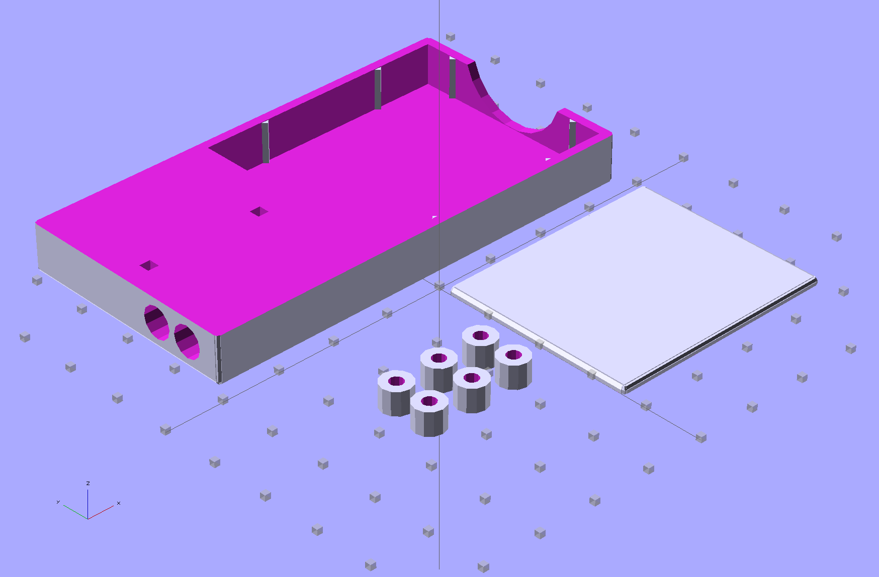
This view of the solid model shows the contact pins, with the lid floating over its alignment pegs (made from snippets of 1.75 mm filament):

The pegs simplify gluing the lid in place, a process for which you can never have enough clamps:

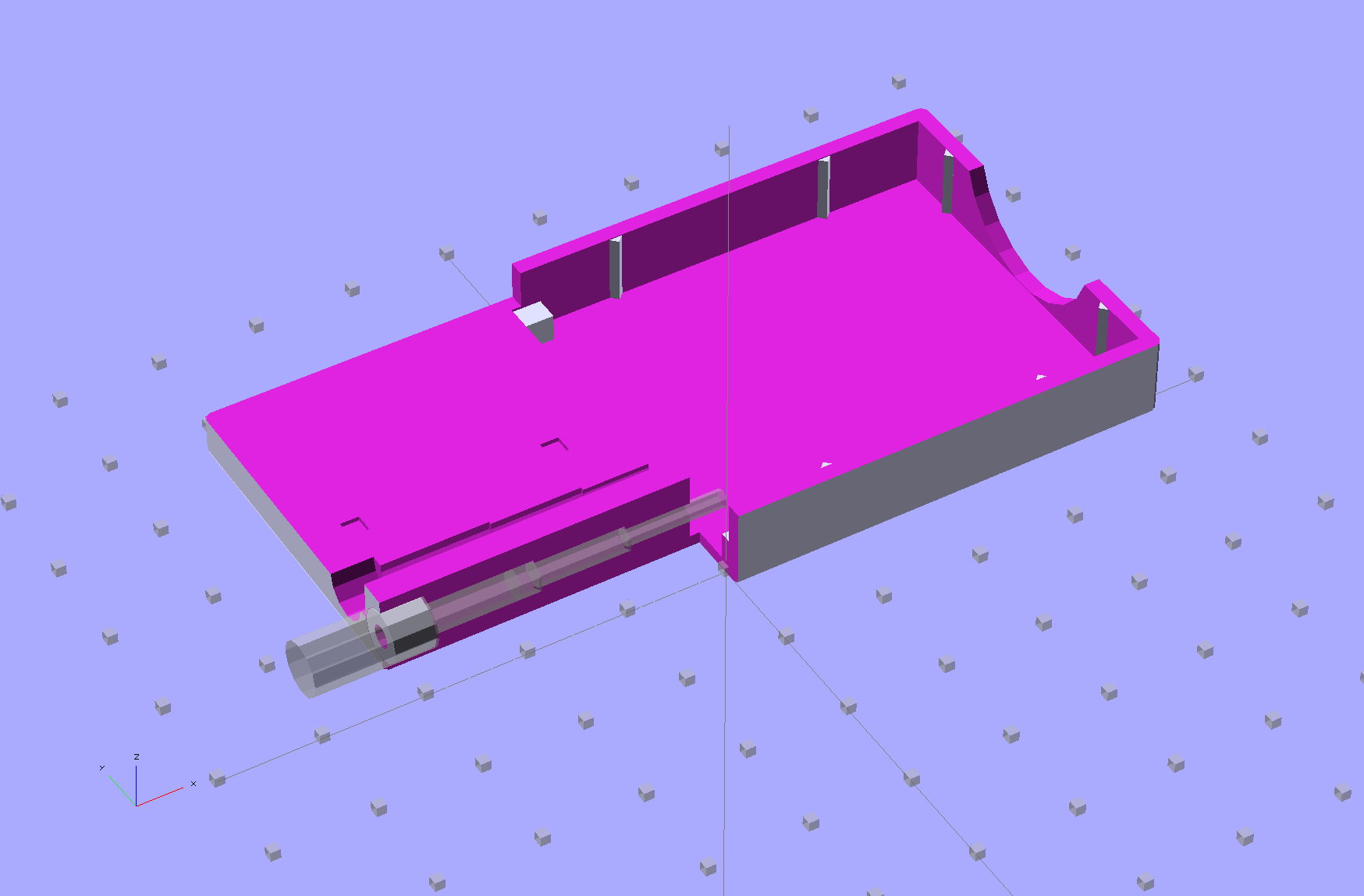
A cutaway shows the stepped holes around the contact pin, with the coil springs being the largest cylinder to the right of the solid-looking plug:
The contact pins look like this, at least after one remembers to slide on all the parts before soldering the wires in place:
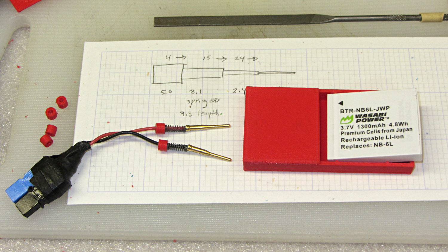
I filed off the inevitable solder bumps, rounded the butt ends with gentle suasion, and generally tidied the pins up so they’re smooth and symmetrical. The springs don’t have a lot of oomph, so wasting any force on friction or binding is a Bad Thing.
The holes require reaming with twist drills for a nice slip fit around the pins. The OpenSCAD script prints out the relevant diameters and depths:
ECHO: "Contact pin tip dia: 1.6"
ECHO: "Drill depth to taper end: 24.1 -- Dia: 2.4"
ECHO: "            to ferrule end: 15 -- Dia: 3.1"
ECHO: "            to plug end: 4 -- Dia: 5.2"
Grab the proper drill in a pin punch, adjust so that length protrudes, and have at it. Making the holes about 0.2 mm larger than nominal works well, although your mileage will definitely vary.
The build layout includes extra retaining plugs, as they tend to go walkabout under the bench:
Add a dab of PVC cement with THF inside the holes and the plugs push firmly into place:
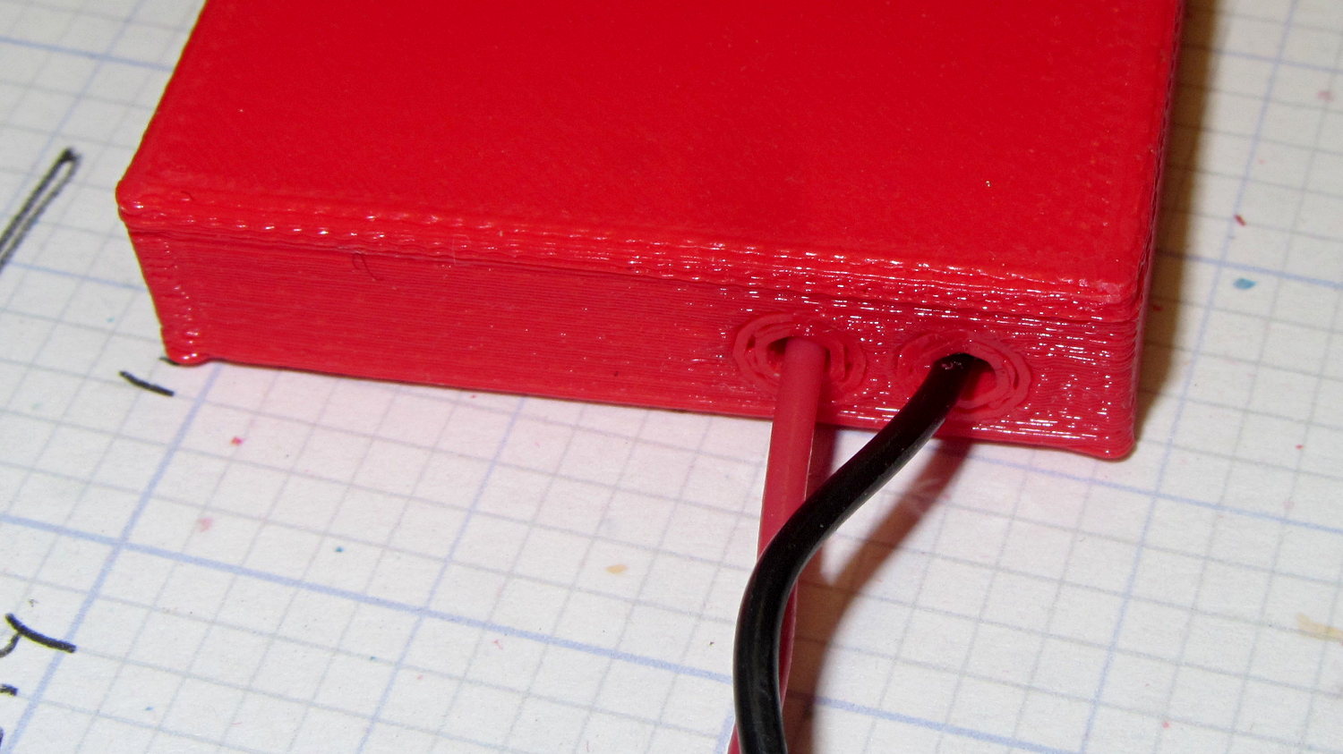
I loves me my 3D printer…
The OpenSCAD source code:
// Holder for Canon NB-6L Li-Ion battery
// Ed Nisley KE4ZNU January 2013

include <MCAD/boxes.scad>

// Layout options

Layout = "Plugs";					//  Show Build Fit Case Lid Pins Plugs AlignPins

//- Extrusion parameters - must match reality!
//  Print with +2 shells and 3 solid layers

ThreadThick = 0.20;
ThreadWidth = 0.40;

HoleWindage = 0.2;

function IntegerMultiple(Size,Unit) = Unit * ceil(Size / Unit);

Protrusion = 0.1;			// make holes end cleanly

inch = 25.4;

BuildOffset = 3.0;			// clearance for build layout

Gap = 8.0;					// separation for Fit parts

//- Battery dimensions - rationalized from several samples
//  Coordinate origin at battery corner by contact plates on bottom surface

BatteryLength = 42.5;
BatteryWidth = 35.5;
BatteryThick =  7.0;

ContactWidth = 2.10;
ContactLength = 4.10;
ContactRecess = 0.85;

ContactOC = 3.18;			// center-to-center across contact face
ContactOffset = 4.45;		// offset from battery edge
ContactHeight = 3.05;		// offset from battery bottom plane

AlignThick = 2.8;			// alignment recesses on contact face
AlignDepth = 2.0;			// into face
AlignWidth1 = 0.7;			// across face at contacts
AlignWidth2 = 2.0;			//  ... other edge

//- Pin dimensions

PinTipDia = 1.6;
PinTipLength = 10.0;

PinTaperLength = 2.3;

PinShaftDia = 2.4;
PinShaftLength = 6.8;

PinFerruleDia = 3.1;
PinFerruleLength = 2.0;

PinLength = PinTipLength + PinTaperLength + PinShaftLength + PinFerruleLength;

ExtendRelax = 1.5 + ContactRecess;		// pin extension when no battery is present
ExtendOvertravel = 1.0;					//  ... beyond engaged position

//- Spring dimensions

SpringDia = 3.1;						// coil OD
SpringMax = 9.3;
SpringLength = SpringMax - 0.3;			// slightly compressed
SpringMin = 4.5;

SpringPlugOD = IntegerMultiple(5.0,ThreadWidth);		// plug retaining the spring
SpringPlugID = 2.0;
SpringPlugLength = IntegerMultiple(4.0,ThreadWidth);
SpringPlugSides = 3*4;

SpringTravel = ExtendRelax + ExtendOvertravel;

//- Holder dimensions

GuideRadius = ThreadWidth;						// friction fit ridges
GuideOffset = 10;
WallThick = 4*ThreadWidth;						// holder sidewalls

BaseThick = 6*ThreadThick;			// bottom of holder to bottom of battery
TopThick = 6*ThreadThick;			// top of battery to top of holder

ThumbRadius = 10.0;			// thumb opening at end of battery

CornerRadius = 3*ThreadThick;			// nice corner rounding

CaseLength = SpringPlugLength + SpringLength + PinLength - ExtendRelax
			+ BatteryLength + GuideRadius + WallThick;
CaseWidth = 2*WallThick + 2*GuideRadius + BatteryWidth;
CaseThick = BaseThick + BatteryThick + TopThick;

AlignPinOD = 1.75;			// lid alignment pins - filament snippets
AlignPinLength = 5.0;
AlignPinInset = 7.0;

//- XY origin at front left battery corner, Z on platform below that

CaseLengthOffset = -(SpringPlugLength + SpringLength + PinLength - ExtendRelax);
CaseWidthOffset = -(WallThick + GuideRadius);
CaseThickOffset = BaseThick;

LidLength = ExtendRelax - CaseLengthOffset;

echo(str("Contact pin tip dia: ",PinTipDia));
echo(str("Drill depth to taper end: ",
		 (SpringPlugLength + SpringLength + PinFerruleLength + PinShaftLength + PinTaperLength),
		 " -- Dia: ",PinShaftDia));
echo(str("            to ferrule end: ",
		  (SpringPlugLength + SpringLength + PinFerruleLength),
		 " -- Dia: ",PinFerruleDia));
echo(str("            to plug end: ",SpringPlugLength,
		 " -- Dia: ",SpringPlugOD));

//----------------------
// Useful routines

module PolyCyl(Dia,Height,ForceSides=0) {			// based on nophead's polyholes

  Sides = (ForceSides != 0) ? ForceSides : (ceil(Dia) + 2);

  FixDia = Dia / cos(180/Sides);

  cylinder(r=(FixDia + HoleWindage)/2,
           h=Height,
	   $fn=Sides);
}

module ShowPegGrid(Space = 10.0,Size = 1.0) {

  Range = floor(50 / Space);

	for (x=[-Range:Range])
	  for (y=[-Range:Range])
		translate([x*Space,y*Space,Size/2])
		  %cube(Size,center=true);

}

//-------------------

//-- Guides for tighter friction fit

module Guides() {
  	  translate([GuideOffset,-GuideRadius,CaseThickOffset])
		PolyCyl(2*GuideRadius,(BatteryThick - Protrusion),4);
	  translate([GuideOffset,(BatteryWidth + GuideRadius),CaseThickOffset])
		PolyCyl(2*GuideRadius,(BatteryThick - Protrusion),4);
	  translate([(BatteryLength - GuideOffset),-GuideRadius,CaseThickOffset])
		PolyCyl(2*GuideRadius,(BatteryThick - Protrusion),4);
	  translate([(BatteryLength - GuideOffset),(BatteryWidth + GuideRadius),CaseThickOffset])
		PolyCyl(2*GuideRadius,(BatteryThick - Protrusion),4);
	  translate([(BatteryLength + GuideRadius),GuideOffset/2,CaseThickOffset])
		PolyCyl(2*GuideRadius,(BatteryThick - Protrusion),4);
	  translate([(BatteryLength + GuideRadius),(BatteryWidth - GuideOffset/2),CaseThickOffset])
		PolyCyl(2*GuideRadius,(BatteryThick - Protrusion),4);

}

//-- Contact pins (holes therefore)

module PinShape() {

  union() {
	cylinder(r=(PinTipDia + HoleWindage)/2,h=(PinTipLength + Protrusion),$fn=6);

	translate([0,0,PinTipLength])
	  cylinder(r=(PinShaftDia + HoleWindage)/2,
			   h=(PinTaperLength + PinShaftLength + Protrusion),$fn=6);

	translate([0,0,(PinLength - PinFerruleLength)])
	  cylinder(r=(PinFerruleDia + HoleWindage)/2,
				h=(PinFerruleLength + Protrusion),$fn=6);

	translate([0,0,(PinLength)])
	  cylinder(r=(SpringDia + HoleWindage)/2,
				h=(SpringLength + Protrusion),$fn=6);

	translate([0,0,(PinLength + SpringLength - HoleWindage)])	// windage for hole length
	  cylinder(r=(SpringPlugOD + HoleWindage)/2,h=3*SpringPlugLength,$fn=SpringPlugSides);

//	  translate([0,0,(PinLength + SpringLength + SpringPlugLength)])
//	  cylinder(r=(SpringPlugOD + HoleWindage)/2,h=2*SpringPlugLength,$fn=SpringPlugSides);	// extend hole
  }

}

module PinAssembly() {

  translate([ExtendRelax,ContactOffset,CaseThickOffset + ContactHeight]) {
	rotate([0,270,0]) {
	  PinShape();												// pins
	  translate([0,(2*ContactOC),0])
		PinShape();
	}
  }

}

//-- Alignment pins

module AlignPins() {

	for (x=[-1,1])
		translate([x*(LidLength - 2*AlignPinInset)/2,0,0])
			rotate(45)
			PolyCyl(AlignPinOD,AlignPinLength);
}

//-- Case with origin at battery corner

module Case() {

  difference() {

	union() {

	  difference() {
		translate([(CaseLength/2 + CaseLengthOffset),
				  (CaseWidth/2 + CaseWidthOffset),
				  (CaseThick/2)])
		  roundedBox([CaseLength,CaseWidth,CaseThick],CornerRadius); 	// basic case shape

		translate([-ExtendOvertravel,-GuideRadius,CaseThickOffset])
		  cube([(BatteryLength + GuideRadius + ExtendOvertravel),
				(BatteryWidth + 2* GuideRadius),
				(BatteryThick + Protrusion)]);						// battery space

	  }

	  Guides();

	  translate([-ExtendOvertravel,-GuideRadius,BaseThick])
		cube([(AlignDepth + ExtendOvertravel),
			  (AlignWidth1 + GuideRadius),
			  AlignThick]);											// alignment blocks
	  translate([-ExtendOvertravel,
				 (BatteryWidth - AlignWidth2),
				 BaseThick])
		cube([(AlignDepth + ExtendOvertravel),
			  (AlignWidth2 + GuideRadius),
			  AlignThick]);

	}

	translate([(-ExtendOvertravel),
			   (CaseWidthOffset - Protrusion),
			   (CaseThickOffset + BatteryThick)])
	  cube([CaseLength,
		    (CaseWidth + 2*Protrusion),
		    (TopThick + Protrusion)]);								// battery access

	translate([(CaseLengthOffset - Protrusion),
			   (CaseWidthOffset - Protrusion),
			   (CaseThickOffset + BatteryThick)])
	  cube([(CaseLength + 2*Protrusion),
		    (CaseWidth + 2*Protrusion),
		    (TopThick + Protrusion)]);								// battery insertion allowance

	translate([(BatteryLength - Protrusion),
			    (CaseWidth/2 + CaseWidthOffset),
			    (CaseThickOffset + ThumbRadius)])
	  rotate([90,0,0])
		rotate([0,90,0])
		  cylinder(r=ThumbRadius,
				   h=(WallThick + GuideRadius + 2*Protrusion),
				   $fn=22);											// remove thumb notch

	PinAssembly();

	translate([-LidLength/2,BatteryWidth/2,CaseThick - TopThick - (AlignPinLength - TopThick/2)])
		AlignPins();
  }

}

module Lid() {

  difference() {
	translate([0,0,(CaseThick/2 - BaseThick - BatteryThick)])
	  roundedBox([LidLength,
				 CaseWidth,CaseThick],CornerRadius);

	translate([0,0,-(CaseThick/2)])
	  cube([(LidLength + 2*Protrusion),
		    (CaseWidth + 2*Protrusion),
		    (CaseThick)],center=true);

	translate([-ExtendRelax,0,-(AlignPinLength - TopThick/2)])
		AlignPins();
  }

}

module PlugShape() {

  difference() {
	cylinder(r=SpringPlugOD/2,h=SpringPlugLength,$fn=SpringPlugSides);
	translate([0,0,-Protrusion])
	  PolyCyl(SpringPlugID,(SpringPlugLength + 2*Protrusion),SpringPlugSides);
  }
}

module Plugs() {
  translate([0,ContactOC,0])
	PlugShape();
  translate([0,-ContactOC,0])
	PlugShape();
}

//-------------------
// Build it!

ShowPegGrid();

if (Layout == "Case")
  Case();

if (Layout == "Lid")
  Lid();

if (Layout == "Plugs")
	for (i=[-1:1])
		translate([i*1.5*SpringPlugOD,0,0])
			Plugs();

if (Layout == "Pins")
  PinShape();

if (Layout == "AlignPins")
  AlignPins();

if (Layout == "Show") {								// reveal pin assembly
  difference() {
	Case();

	translate([(CaseLengthOffset - Protrusion),
			   (CaseWidthOffset - Protrusion + WallThick + ContactOffset + ContactOC),
			   (BaseThick + ContactHeight)])
	  cube([(-CaseLengthOffset + Protrusion),
			 (CaseWidth + 2*Protrusion),
			 CaseThick + BaseThick - ContactHeight + Protrusion]);

	translate([(CaseLengthOffset - Protrusion),
			   (CaseWidthOffset - Protrusion),
			   -Protrusion])
	  cube([(-CaseLengthOffset + Protrusion),
			 (WallThick + GuideRadius + ContactOffset + Protrusion),
			 CaseThick]);
  }

  translate([ExtendRelax,ContactOffset,(CaseThickOffset + ContactHeight)]) {	// pins
	rotate([0,270,0]) {
	  %PinShape();
//	  translate([0,(2*ContactOC),0])
//		%PinShape();
	}
  }

  translate([CaseLengthOffset,ContactOffset,(CaseThickOffset + ContactHeight)])
	rotate([0,90,0])
	  PlugShape();
}

if (Layout == "Build") {
  translate([-(CaseLength/2 + CaseLengthOffset),-(CaseWidthOffset - BuildOffset),0])
	Case();
  translate([CaseWidth/2,(CaseLengthOffset/2 - BuildOffset),0])
	rotate([0,0,90])
	  Lid();
  for (i=[-1:1])
	translate([CaseLengthOffset/2 + i*1.5*SpringPlugOD,-CaseWidth/2,0])
		Plugs();
}

if (Layout == "Fit") {
  Case();
  translate([(-LidLength/2 + ExtendRelax),
			(CaseWidth/2 + CaseWidthOffset),
			(BaseThick + BatteryThick + Gap)])
	  Lid();
  translate([ExtendRelax,ContactOffset,CaseThickOffset + ContactHeight]) {	// pins
	rotate([0,270,0]) {
	  %PinShape();
	  translate([0,(2*ContactOC),0])
		%PinShape();
	}
  }

  translate([CaseLengthOffset,
			(ContactOffset + ContactOC),
			(CaseThickOffset + ContactHeight)])
  rotate([0,90,0])
	Plugs();

  translate([-LidLength/2,BatteryWidth/2,CaseThick])
#	AlignPins();

}