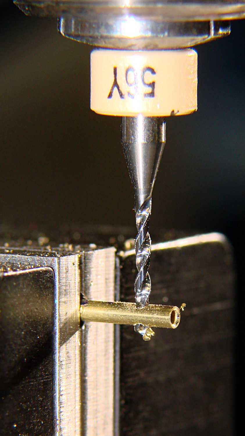
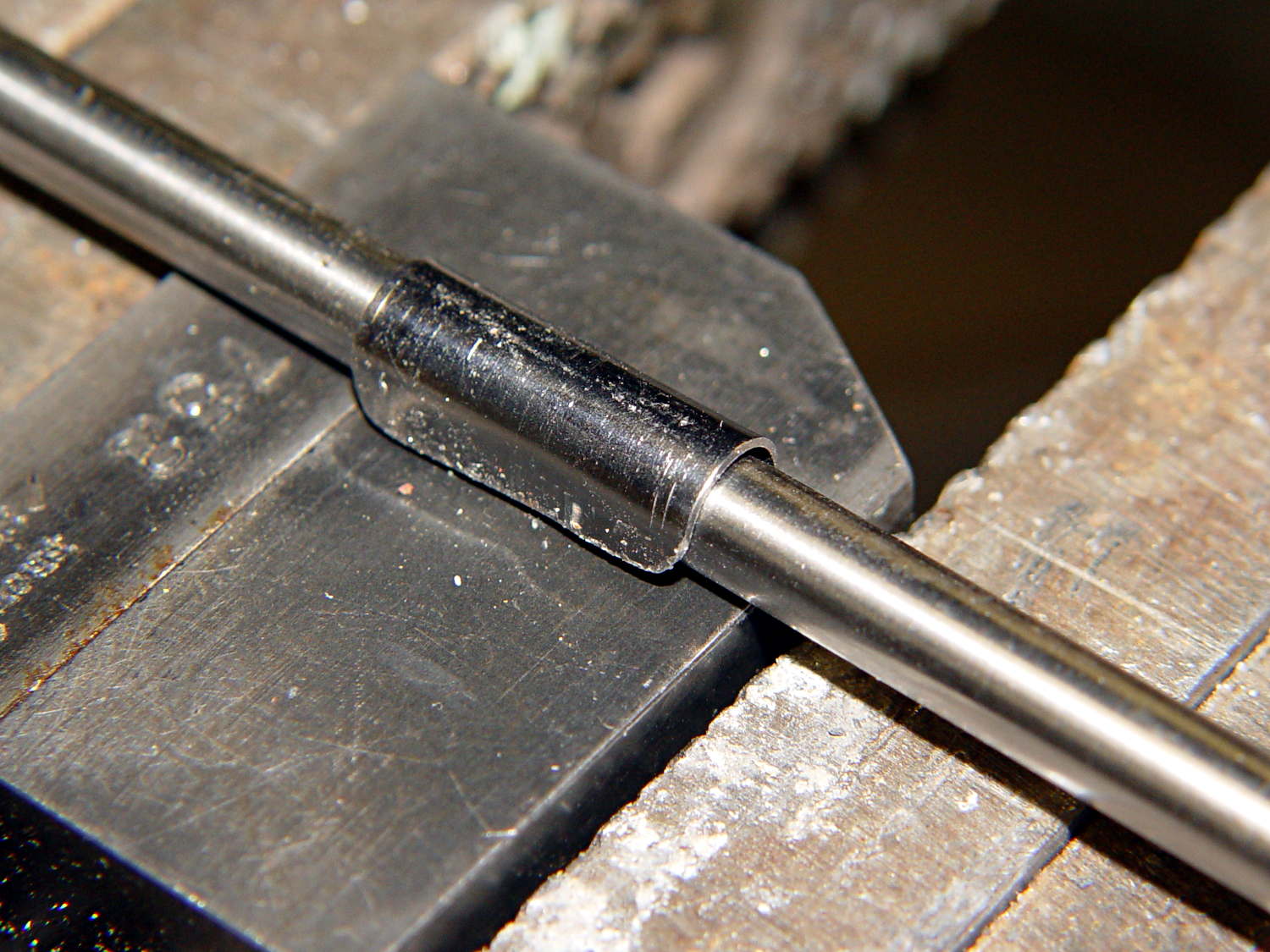
A few trips with the M2 convinced me that the cable to the relocated Z-min switch along the front of the X gantry needed a clip on each end and should not run under the gantry. This time I used the full width of the steel strap and bashed a neater curve around a length of drill rod:
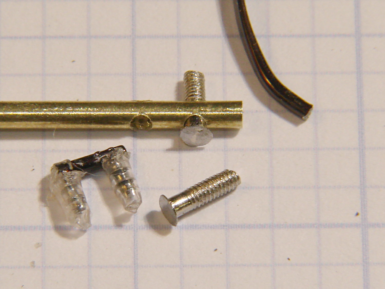
The new clips look a bit better with straight edges:

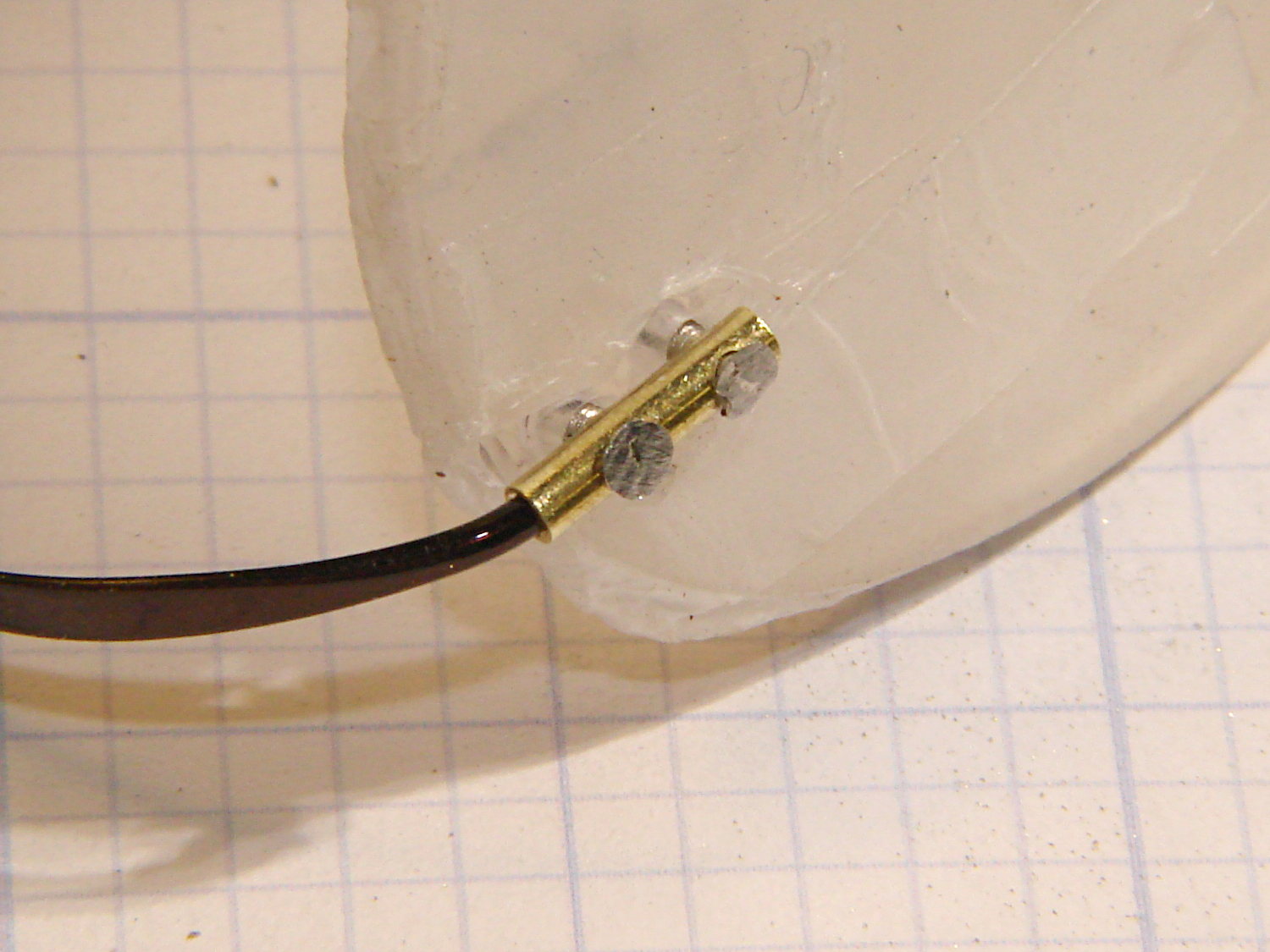
The top view shows the new clips and cable location:

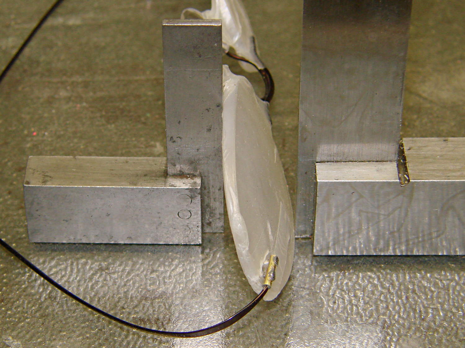
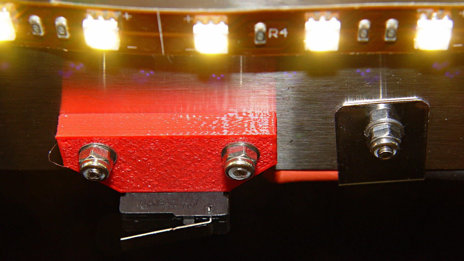
While I was at it, I trimmed the edges off the switch mounting block. Rather than figure out the trig required to hack off the corners, I applied linear_extrude() to a polygon() defined by some obvious points, then poked the same holes in the block:

It pretty much vanishes in the top view, but here’s a view from the +Y end of the platform:
Despite all that maneuvering, the G92 Z-4.55 touchoff value remained the same!
If you’ve forgotten why all this makes sense, it’s a first pass at detecting the actual build platform position. The stock M2 uses that switch to detect the top of a screw attached to the Z-axis stage, which means it can’t sense the actual platform. The Z-min switch I added to the Thing-O-Matic convinced me that was the only way to fly; given the TOM’s plywood-and-acrylic frame, it was essentially mandatory.
Mounting the switch on the extruder would allow probing the entire platform, which would allow on-the-fly correction for both average height and (non-)flatness, but that’s a whole ‘nother project.
The OpenSCAD source code:
// Block to mount M2 Z-min switch on X gantry
// Ed Nisley KE4ZNU - Oct 2013

//- Extrusion parameters - must match reality!

ThreadThick = 0.25;
ThreadWidth = 0.40;

function IntegerMultiple(Size,Unit) = Unit * ceil(Size / Unit);

Protrusion = 0.1;

HoleWindage = 0.2;

//- Sizes

SwitchLength = 20.0;					// switch size across front of block

SwitchScrewOD = 2.05;					// microswitch screw tapping
SwitchScrewOC = 9.5;					//  ... on-center spacing

GantryScrewOD = 3.0;					// X rail screw clearance
GantryScrewOC = 25.0;					//  ... on-center spacing along X
GantryScrewOffset = 12.0;				//  ... Y offset from gantry front

BlockSize = [1.5*GantryScrewOC,17.0,5.0];			// XYZ dimensions as mounted
HalfBlock = BlockSize/2;

SwitchScrewLength = BlockSize[1] - 5*ThreadWidth;	// net length of switch screws
echo("Max switch screw length: ",SwitchScrewLength + 5.0);		// ... allow switch thickness

ChamferAngle = atan((BlockSize[0] - SwitchLength)/(BlockSize[1]/2));
echo("Chamfer Angle: ",ChamferAngle);

//- Adjust hole diameter to make the size come out right

module PolyCyl(Dia,Height,ForceSides=0) {			// based on nophead's polyholes

  Sides = (ForceSides != 0) ? ForceSides : (ceil(Dia) + 2);

  FixDia = Dia / cos(180/Sides);

  cylinder(r=(FixDia + HoleWindage)/2,h=Height,$fn=Sides);
}

//- Put peg grid on build surface

module ShowPegGrid(Space = 10.0,Size = 1.0) {

  RangeX = floor(100 / Space);
  RangeY = floor(125 / Space);

	for (x=[-RangeX:RangeX])
	  for (y=[-RangeY:RangeY])
		translate([x*Space,y*Space,Size/2])
		  %cube(Size,center=true);

}

//- Define basic block shape

module BaseBlock() {
	translate([0,-GantryScrewOffset,0])
		linear_extrude(height=BlockSize[2])
		polygon(points=[[-HalfBlock[0],BlockSize[1]],
						[HalfBlock[0],BlockSize[1]],
						[HalfBlock[0],HalfBlock[1]],
						[SwitchLength/2,0],
						[-SwitchLength/2,0],
						[-HalfBlock[0],HalfBlock[1]]
						]);
}

//- Build it

ShowPegGrid();

difference() {
	BaseBlock();
	for (i=[-1,1]) {
		translate([i*GantryScrewOC/2,0,-Protrusion])
			rotate(-90)
				PolyCyl(GantryScrewOD,(BlockSize[2] + 2*Protrusion));
		translate([i*SwitchScrewOC/2,-(GantryScrewOffset + Protrusion),BlockSize[2]/2])
			rotate([-90,0,0])
				rotate(90)
					PolyCyl(SwitchScrewOD,(SwitchScrewLength + Protrusion));
	}
}