Ed Nisley's Blog: Shop notes, electronics, firmware, machinery, 3D printing, laser cuttery, and curiosities. Contents: 100% human thinking, 0% AI slop.
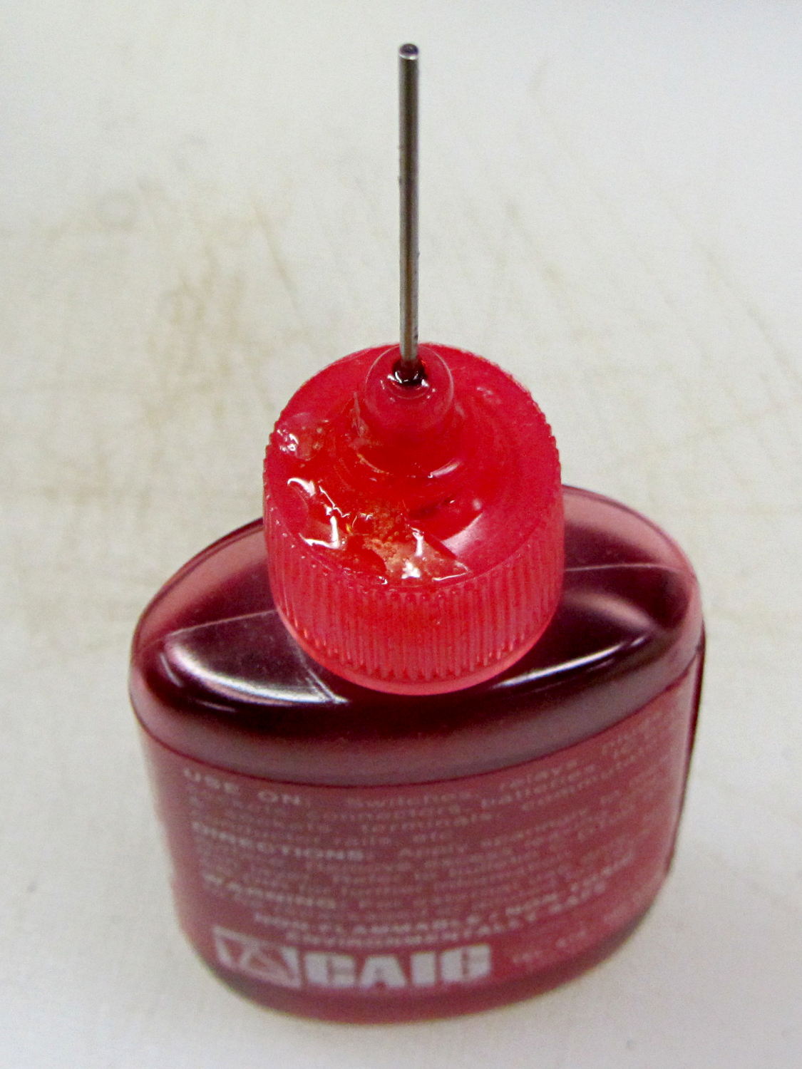
For years this bottle of DeoxIT has been covered with a very thin layer of red juice, despite having the lid screwed firmly in place and a cap (removed here) pushed over the tube:
Caig DeoxIT bottle – lid crack repair
Turns out that there’s a minute crack in the cap. Every time I use the bottle, I refresh the oil layer on the inside of the bottle, which then gets pumped outside through capillary action. I’d been keeping the bottle in a tall ziploc baggie, specifically to contain the oil, and always assumed it was a simple leak.
The bottle still contains a lifetime supply of DeoxIT that may become a cherished family heirloom, one to be handed down through the generations. I can’t think of a better applicator, either, so I’m kind of stuck with that cap.
The cap is, of course, un-bondable polyethylene covered with thin oil, so there’s no possible way to repair it. I wiped it down with alcohol and acetone, then quick-like-a-bunny dabbed on a blob of Duco cement (which is the irregular shape on the cap) and worked it into the crack, in the hope it would stick well enough to reduce the pumping.
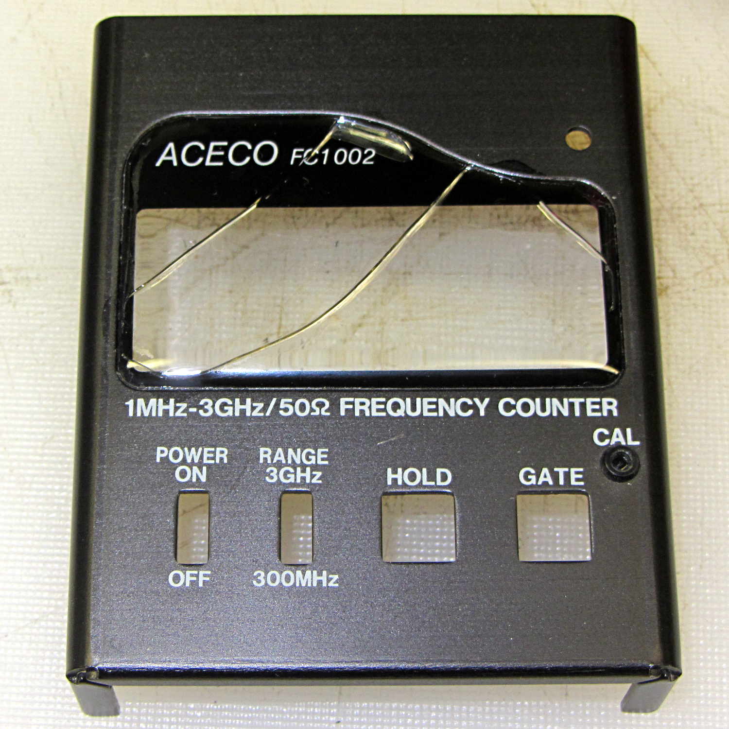
The plastic faceplate over the display cracked quite a while ago:
FC1002 Frequency Counter – cracked plastic
I don’t recall dropping the poor thing. Given the interesting pattern, it could be inherent stress that finally let loose as the plastic aged.
While I have it apart to rebuild the battery pack (more on that later), I’ve been easing acetone/MEK into those cracks by capillary attraction in the hopes of dissolving just enough plastic to rejoin them, without slobbering solvent all over the faceplate and scarring it.
If all else fails, I suppose I can mill out a replacement from thin acrylic sheet, but those nicely rounded cast / molded edges lie well beyond my abilities…
I did five minutes of standup comedy at yesterday’s MHV Lug meeting, pointing out some of the more interesting ways to compromise a PC when you have an infinite budget for development and consumables.
You don’t get my patter with the PDF (unless you had access to the room’s bugging hardware), but the links may come in handy in the unlikely event you haven’t been following the story closely.
If you have a security clearance or are in line for one, you probably shouldn’t click on the link, because it contains copies of pages from the leaked NSA catalog:
A discussion on the Makergear Google Group about a heated enclosure prompted me to run the numbers for cooling stepper motors with water, rather than fans and finned heatsinks.
The general idea comes from my measurements of the air-cooled heatsink stuck to a stepper’s end cap. The metal-to-metal conductivity works surprisingly well and reduces the case temperature to slightly over ambient with decent airflow through the heatsink; epoxying a cold plate to the end cap should work just as well. A NEMA 17 stepper case is 42.3 mm square, so a standard 40 mm square CPU cooling plate will fit almost exactly.
The question then becomes: how much water flow do you need to keep the motors cool?
Some numbers:
Water’s heat capacity is 4.2 J/g·K
1 J = 1 W·s, 1 W = 1 J/s
NEMA 17 motors dissipate about 5 W (13 W if you’re abusing them)
We’ll cool all four motors in parallel, for a total of 20 W
Allow a 5 K = 5 °C temperature rise in each cold plate
Rub them all together:
(20 J/s) / (5 K * (4.2 J/g·K)) = 0.95 g/s
For water, 1 g = 1 cc, so the total flow is 1 cc/s = 3600 cc/h = 3.6 liter/h, which, here in the US, works out to a scant 1 gallon/hour. It’s tough getting a pump that small and cheap flowmeters run around 0.5 liter/m…
If you don’t want a pump. put an aquarium up on a (sturdy) shelf and drain it through the cold plates. A cubic foot of water, all eight gallons and sixty-some-odd pounds of it, will last 8 hours, which should be enough for most printing projects.
If you want reliability, drain the coolers into a sump with a float switch (high = on), put another float switch (high = off) on the aquarium, and have the pump top up the aquarium. If the pump fails, your steppers stay cool for the next 8 hours. Heating the water about 5 °C during 8 hours won’t require active cooling.
Now, managing the hoses leading to the X axis stepper may be challenging, but a cable drag chain would control the rest of the wiring, too.
Browning HP Mag Blocks – stainless and plastic – side
It’s actually bronze-infused stainless steel powder, so it’s not exactly solid steel. The parts spend a day rattling around in a vibratory polisher that slightly rounds off their edges and smooths the surface, but (as with all 3D printed objects) you must learn to love the results; it’s certainly more photogenic than the black plastic version from my M2.
The bottom view shows the hole I added to reduce the metallic volume; they charge a bit under $0.01/mm3, which encourages airy design:
Browning HP Mag Blocks – stainless and plastic – bottom
A cross-section view of the solid model shows the interior structure:
The vent pipes are somewhat larger than in the plastic version and, obviously, I didn’t include the yellow support structures in the model I sent to Shapeways.
Their specs give a minimum wall thickness of 3.0 mm, which I’m definitely pushing on some of the internal features. The pipes came out perfectly, as nearly as I can tell, although some polishing media did get wedged in the smaller hole. Air passes freely across the top, which is the important part.
Although the specs list a ±2 mm (!) tolerance, a comment in a Shapeways forum said that applies to larger objects, with 0.2 mm being typical for smaller objects. The steel and plastic parts match within 0.2 mm of the nominal model dimensions, so that lower tolerance seems about right; I have no idea how consistent it is.
Another comment recommended carbide tools for secondary operations and that’s definitely true; I wrecked a perfectly good HSS tap trying to thread the central hole. Fortunately, I made the block slightly smaller outside and slightly larger inside, specifically to avoid having a deep thread; I intend to ram a standard M3x0.5 SHCS into that hole and epoxy it in place without worrying about thread damage.
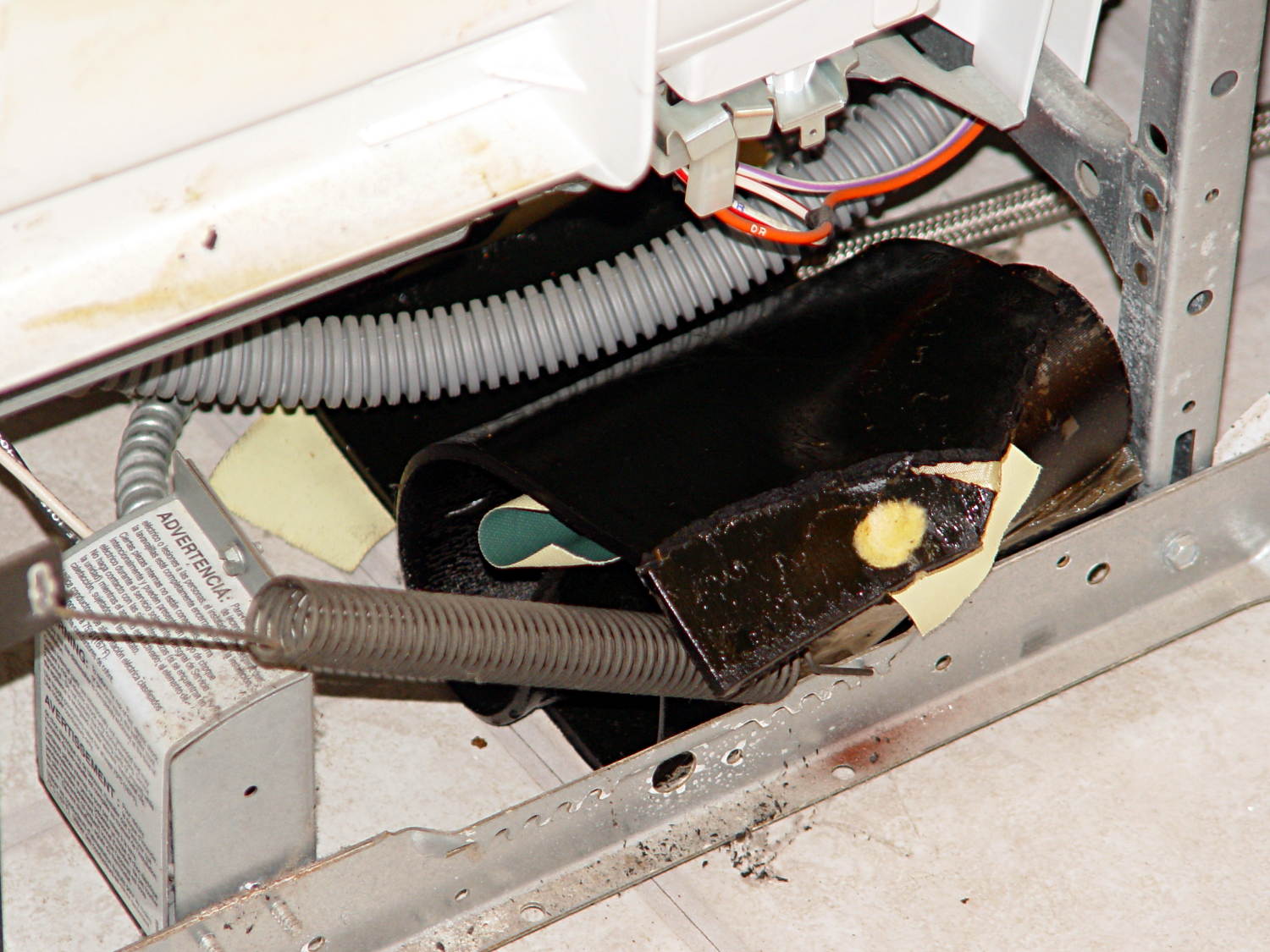
The springs balancing the dishwasher door started twanging again, which I now know is the diagnostic sign that an asphalt sound deadening sheet has slipped off the tub. A sheet on the right side almost perpetrated a clean escape, but the flap drooping over the spring gave it away:
Dishwasher sound deadener – slipped away
Another sheet on the left side was inching away, but hadn’t quite gotten over the fence:
Dishwasher sound deadener – slipping away
They’re pretty much a rigid solid at room temperature:
It puts one in mind of the pitch drop experiments now running in various labs. In this case, we now know it takes about four years for an asphalt sheet to slide completely off the tub; those two sheets were definitely in place when I buttoned it up after the previous one broke free.
I applied a heat gun to soften the sheets, then smoothed them around the tub again. This time I applied long strips of Gorilla Tape from one side to the other, rather than short strips of ordinary duct tape along the edges, and maybe this fix will outlast either the dishwasher or our tenure here, whichever comes first…