The Nyloc nut atop that modified quilting foot requires more grip than fingers can provide:
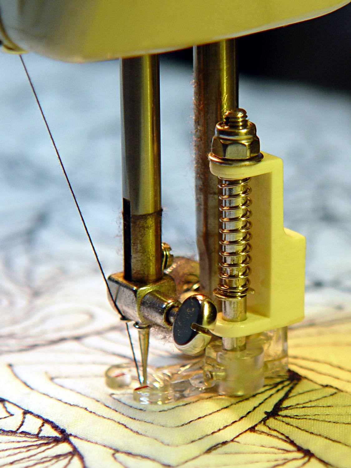
The “precision” wrench I adapted to that nut works for small adjustments, but for larger ones it’s easier to take the foot off and spin this knob:
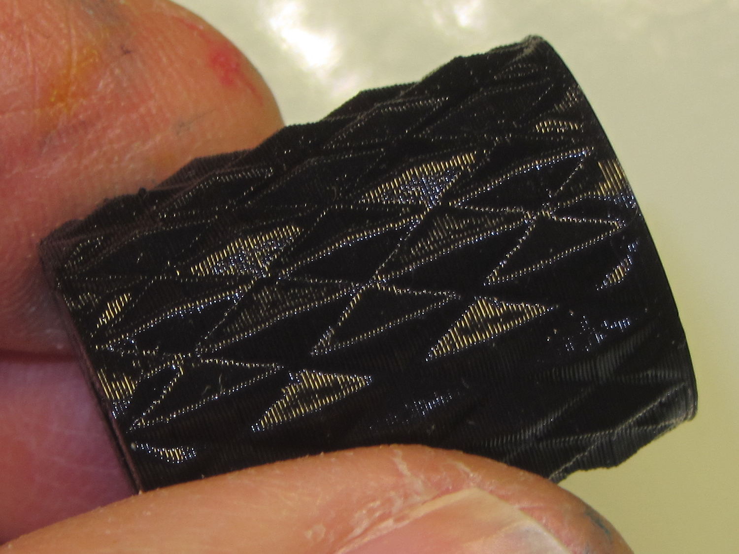
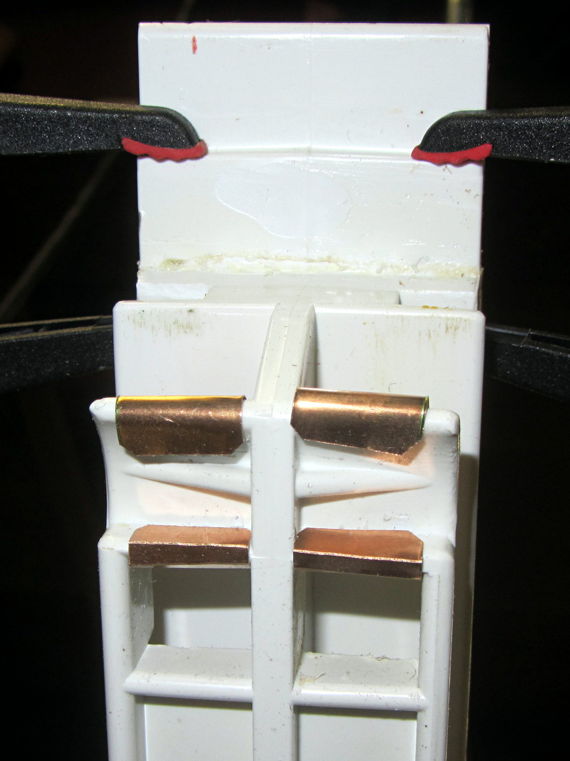
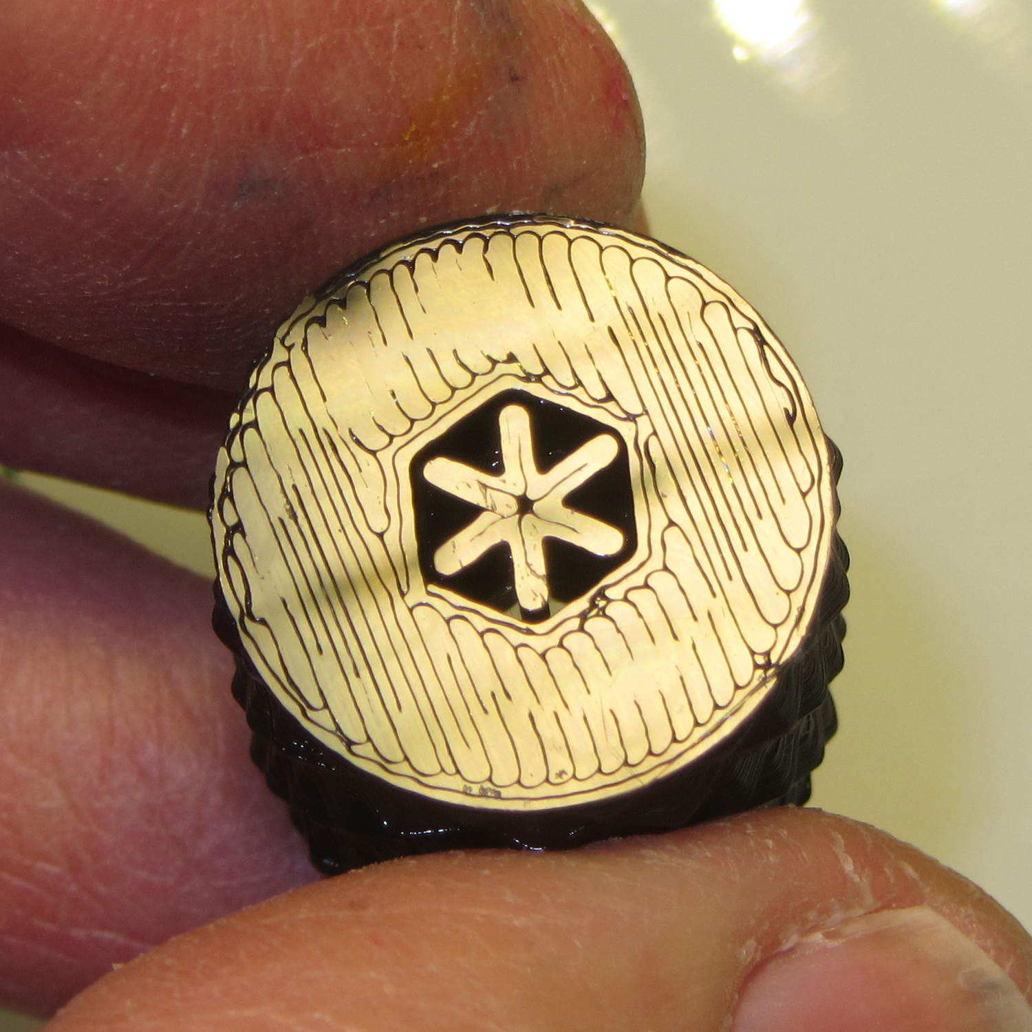
It has a hex opening in each end that fits the nut, with a through hole for the bolt. The top looks exactly like you’d expect:

The bottom needs a bit of support:
The solid model shows off the support in color:
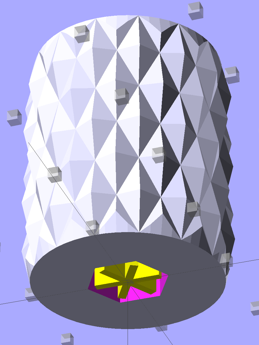
The OpenSCAD source code doesn’t have many surprises:
// Quilting foot knob
// Ed Nisley KE4ZNU January 2013

use <knurledFinishLib_v2.scad>

//- Extrusion parameters must match reality!
//  Print with +1 shells and 3 solid layers

ThreadThick = 0.20;
ThreadWidth = 0.40;

HoleWindage = 0.2;

function IntegerMultiple(Size,Unit) = Unit * ceil(Size / Unit);

Protrusion = 0.1;			// make holes end cleanly

//----------------------
// Dimensions

KnobOD = 20.0;
KnobLength = 25.0;
KnobSides = 12;

DiamondLength = KnobLength/3;
DiamondWidth = DiamondLength/2;
DiamondDepth = 1.0;

NutOD = 7.0;				// across flats!
NutLength = 6.0;
ScrewOD = 4.0;

DoSupport = true;

//----------------------
// Useful routines

module PolyCyl(Dia,Height,ForceSides=0) {			// based on nophead's polyholes

  Sides = (ForceSides != 0) ? ForceSides : (ceil(Dia) + 2);

  FixDia = Dia / cos(180/Sides);

  cylinder(r=(FixDia + HoleWindage)/2,
           h=Height,
	   $fn=Sides);
}

module ShowPegGrid(Space = 10.0,Size = 1.0) {

  RangeX = floor(100 / Space);
  RangeY = floor(125 / Space);

	for (x=[-RangeX:RangeX])
	  for (y=[-RangeY:RangeY])
		translate([x*Space,y*Space,Size/2])
		  %cube(Size,center=true);

}

module Knob() {
	rotate(180/Sides) {
		difference() {
//			cylinder(r=KnobOD/2,h=KnobLength,$fn=KnobSides);
			render(convexity=10)
			knurl(k_cyl_hg=KnobLength,
				  k_cyl_od=KnobOD,
				  knurl_wd=DiamondWidth,
				  knurl_hg=DiamondLength,
				  knurl_dp=DiamondDepth,
				  e_smooth=DiamondLength/2);
			translate([0,0,-Protrusion])
				PolyCyl(ScrewOD,(KnobLength + 2*Protrusion),6);
			translate([0,0,(KnobLength - NutLength)])
				PolyCyl(NutOD,(NutLength + Protrusion),6);
			translate([0,0,-Protrusion])
				PolyCyl(NutOD,(NutLength + Protrusion),6);
		}
	}
}

module Support() {
	color("Yellow")
		for (Seg=[0:5]) {
			rotate(360*Seg/6)
			translate([0,0,(NutLength - ThreadThick)/2])
				cube([(NutOD - 1*ThreadWidth),
						2*ThreadWidth,
						(NutLength - ThreadThick)],
						center=true);
			}
}

//----------------------
// Build them!

ShowPegGrid();

Knob();

if (DoSupport)
	Support();
Mary likes it… and thinks I’m being silly. She’s right, of course.