The Smell of Molten Projects in the Morning

Ed Nisley's Blog: Shop notes, electronics, firmware, machinery, 3D printing, laser cuttery, and curiosities. Contents: 100% human thinking, 0% AI slop.

Category: Machine Shop

Mechanical widgetry

  • Sony HDR-AS30V Audio vs. Wind Noise

    With the Sony HDR-AS30V in its skeleton frame atop my bike helmet, the audio track for all my rides consists entirely of horrendous wind noise. You can get an idea of the baseline quality from the sound track of a recent Walkway Over The Hudson crossing.

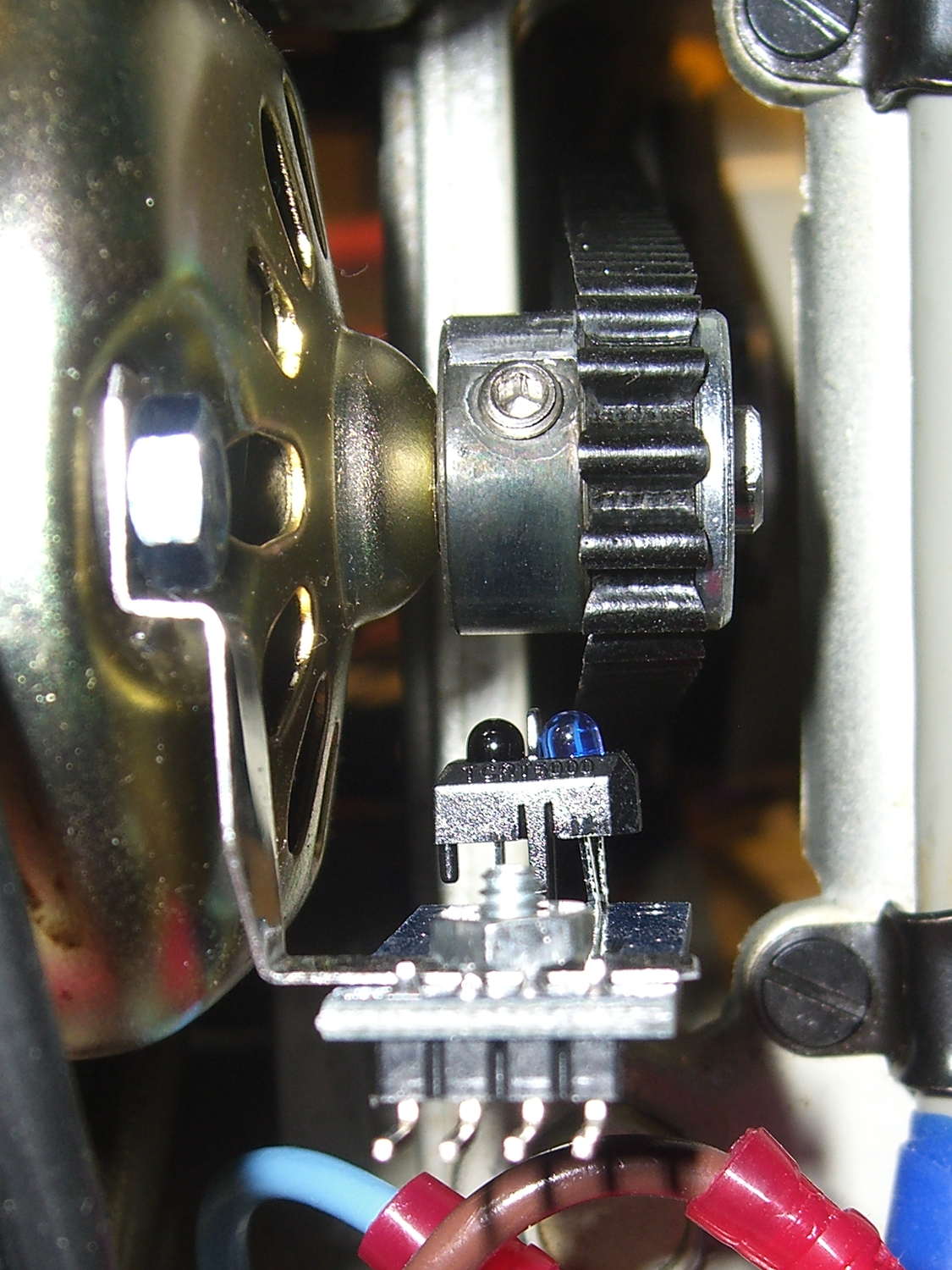
    The camera has two mics, although I’m not sure 15 mm of separation really produces meaningful stereo sound:

    Sony HDR-AS30V - front view
    Sony HDR-AS30V – front view

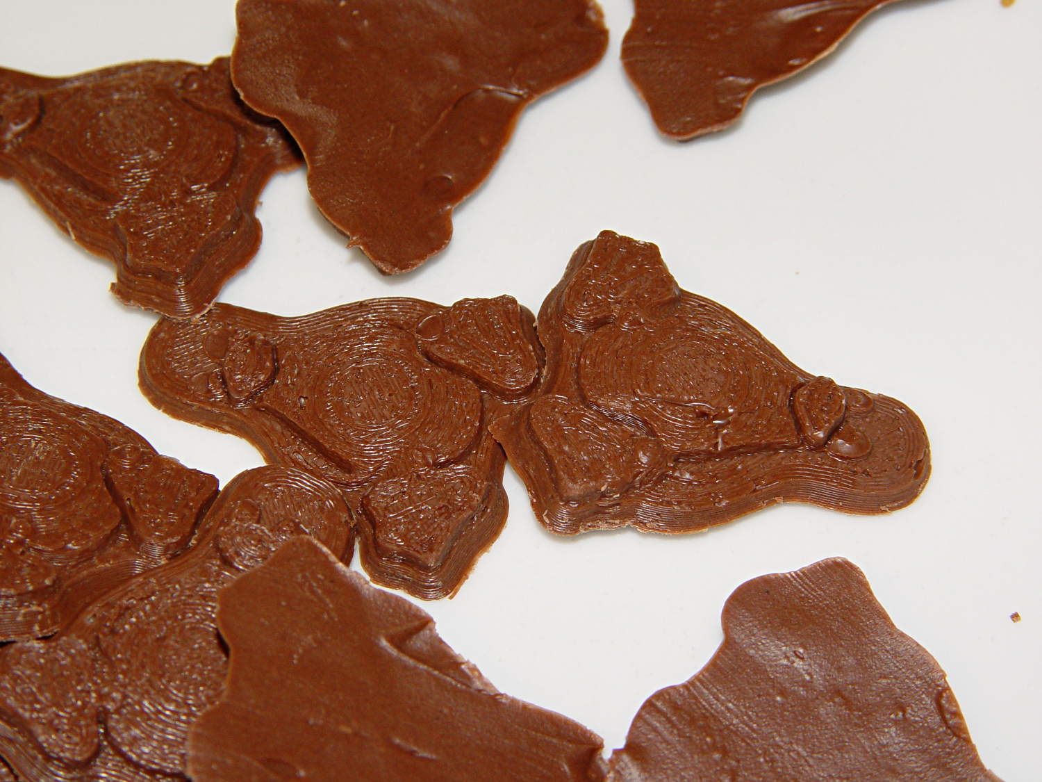
    Note that two of the five pores on each side are closed flat-bottom pits. As with earbud vents , it must be a stylin’ thing.

    I added a rounded pad of the same acoustic foam that forms an effective wind noise buffer for the boom mic:

    Sony HDR-AS30V - foam mic cover
    Sony HDR-AS30V – foam mic cover

    That reduced the overall noise load by buffering direct wind impact, but non-radio conversations remained unintelligible; there’s just too much low-frequency energy.

    Surprisingly, closing the mic pores with ordinary adhesive tape didn’t impair the audio in a quiet room:

    Sony HDR-AS30V - closed mic pores
    Sony HDR-AS30V – closed mic pores

    Out on the road that’s even better than foam over open mic pores; I think it reduces the peak volume enough that the internal compression can regain control. Sticking the foam pad over the tape slightly reduced the noise during high-speed (for me, anyhow) parts of the ride, but didn’t make much difference overall.

    The wind noise remains too high for comfort, even if I can now hear cleats clicking into pedals, shifters snapping, and even the horrible background music when I’m stopped next to the Mobil gas station on the corner.

    Next step: raid the cloth scrap box for a flap of faux fur to make a mic mop. This might be an opportunity to recycle some roadkill

  • Poughkeepsie Mini Maker Faire: 3D Printing Status Report

    The Poughkeepsie paper had a short writeup on last Saturday’s Mini Maker Faire, featuring exactly one picture (it’s their Copyrighted Work, so I can’t show it here): my hotrodded M2 with a platform of Tux penguins from the chocolate mold project.

    I passed out samples:

    Tux Gradient 4x4 - milk chocolate detail
    Tux Gradient 4×4 – milk chocolate detail

    Of course, I told the kids that Santa was on their side for getting a 3D printer under the tree…

    Rumors from usually reliable sources indicate the two other 3D printers at the Faire had, shall we say, reliability issues and generally weren’t running. The M2 ran continuously from 10 am through 4 pm, cranking out eight Tuxes at a time, with no trouble at all; perhaps that’s why it got its picture in the paper.

    By and large: It. Just. Works.

    I did a presentation on (my opinion of) the current state of Personal 3D Printing, using jimc’s impeccable projects to show how enough skill can cure the usual striated sidewalls, plus other examples and advice from MakerGear forum members.

    A good time was had by all!

    My voice may return by early next week…

  • Kenmore 158: Acceleration and Deceleration

    Plotting the motor RPM every 500 ms while increasing the nominal current by 50 mA per step from 550 mA:

    Motor RPM vs Current Steps - Accelerating
    Motor RPM vs Current Steps – Accelerating

    And then downward from 950 mA:

    Motor RPM vs Current Steps - Decelerating
    Motor RPM vs Current Steps – Decelerating

    No, the steps aren’t the same size going down as they are going up. The nominal current setting is open-loop = constant DAC values: the actual current for a given DAC value varies as the transistors heat up.

    The motor starts running at 3700 RPM with 550 mA and stops well under 1000 RPM with 400 mA. Obviously, starting slowly and smoothly will require finesse: a swift kick of maybe 600 mA to get it turning, then immediately drop to 400-ish mA for slow stitching. Those currents must be the actual motor current, not the nominal DAC values, so the motor sees the proper current regardless of the transistor temperature.

    The sewing machine requires four samples = two seconds to stabilize at each new speed on the way up, so the mechanical time constant is 2/3 second. Trying to stabilize the speed with a loop running much faster than that will certainly cause oscillation.

    There is absolutely no deceleration control authority: reducing the current allows freewheeling as the machinery slows down to match the current. The undershoot after each step on the way down lasts 2.5 s, then there’s a persistent oscillation with a period of 3 s.

    Forcing the firmware to run slowly enough to match the hardware should pose an interesting challenge… you don’t want to lock up the UI while the motor stabilizes!

  • Kenmore 158: Bubble Sorted Motor Current Sampling

    Because the ET227 transistor acts as a current limiter, the motor current waveform has flat tops at the level set by the DAC voltage. However, the current depends strongly on the temperature of all those transistor junctions, with some commutation noise mixed in for good measure, so the firmware must measure the actual current to know what’s going on out there.

    Here’s one way to pull that off:

    Motor current - ADC sample timing
    Motor current – ADC sample timing

    The upper waveform shows the motor current sporting flat tops at 650 mA.

    The lower waveform marks the current measurement routine, with samples taken just before the falling edge of the first nine pulses. The (manually tweaked) delay between the samples forces them to span one complete cycle of the waveform, but they’re not synchronized to the power line. Remember that the motor runs from a full wave rectifier, so each “cycle” in that waveform is half of a normal power line cycle.

    Given an array containing those nine samples, the routine must return the maximum value of the waveform, ignoring the little glitch at the start of the flat top and taking into consideration that the waveform won’t have a flat top (or much of a glitch) when the current “limit” exceeds the maximum motor current.

    After a bit of fumbling around with the scope and software, the routine goes like this:

    • Collect samples during one current cycle
    • Sort in descending order
    • Ignore highest sample
    • Return average of next two highest samples

    Given that the array has only nine samples, I used a quick-and-dirty bubble sort. The runt pulse at the end of the series in the bottom waveform brackets the sort routine, so it’s not a real time killer.

    Seeing as how this is one of the very few occasions I’ve had to sort anything, I wheeled out the classic XOR method of exchanging the entries. Go ahead, time XOR against swapping through a temporary variable; it surely doesn’t make any difference at all on an 8-bit microcontroller.

    The sampling code, with all the tracing stuff commented out:

    //------------------
    // Sample current along AC waveform to find maximum value
    //	this is blocking, so don't call it every time around the main loop!
    
    #define NUM_I_SAMPLES	9
    
    unsigned int SampleCurrent(byte PinNum) {
    	
    unsigned int Samples[NUM_I_SAMPLES];
    unsigned int AvgSample;
    byte i,j;
    	
    //	digitalWrite(PIN_SYNC,HIGH);
    	for (i=0; i < NUM_I_SAMPLES; i++) {				// collect samples
    //		digitalWrite(PIN_SYNC,HIGH);
    		Samples[i] = ReadAI(PinNum);
    //		digitalWrite(PIN_SYNC,LOW);
    		delayMicroseconds(640);
    	}
    //	digitalWrite(PIN_SYNC,LOW);
    	
    //	digitalWrite(PIN_SYNC,HIGH);							// mark start of sorting
    	for (i=0; i < (NUM_I_SAMPLES - 1); i++)
    		for (j=0 ; j < (NUM_I_SAMPLES - 1 - i); j++)
    			if (Samples[j] < Samples[j+1]) {
    				Samples[j] ^= Samples[j+1];					// swap entries!
    				Samples[j+1] ^= Samples[j];
    				Samples[j] ^= Samples[j+1];
    			}
    //	digitalWrite(PIN_SYNC,LOW);								// mark end of sorting
    	
    //	printf("Samples: ");
    //	for (i=0; i < NUM_I_SAMPLES; i++)
    //		printf("%5d,",Samples[i]);
    	
    	AvgSample = (Samples[1] + Samples[2])/2;				// discard highest sample
    //	printf(" [%5d]\r\n",AvgSample);
    	
    	return AvgSample;
    
    }
    
  • Kenmore 158: Motor RPM Sensor Deglitching

    The setscrew in the motor pulley lies directly in the path of the photosensor:

    TCTR5000 Motor RPM Sensor - side view
    TCTR5000 Motor RPM Sensor – side view

    Which produces a glitch in the rising edge of the digital output as the pulley rotates from the dark to the light section:

    Motor Sensor - Rising Edge Glitch
    Motor Sensor – Rising Edge Glitch

    The RPM signal goes to Arduino pin D2, where each falling edge triggers an interrupt handler:

    const byte PIN_MOTOR_REV = 2;		// DI - IRQ 0 (must be D2)
    
    ... snippage...
    
    void setup() {
    ... snippage ...
    
        pinMode(PIN_MOTOR_REV,INPUT_PULLUP);
        attachInterrupt((PIN_MOTOR_REV - 2),ISR_Motor,FALLING);			// one IRQ / motor revolution
    
     ... snippage ...
    }
    

    The maximum motor speed is about 11 kRPM, so interrupts should be at least 5.5 ms apart and the digital input should be low. If that’s true, then the code updates a bunch of useful information:

    struct pulse_t {
     byte Counter;
     unsigned long TimeThen;
     unsigned long Period;
     word RPM;
     byte State;
    };
    
    struct pulse_t Motor;
    
    ... snippage ...
    
    //------------------
    // ISR to sample motor RPM sensor timing
    
    void ISR_Motor(void) {
    
    static unsigned long Now;
    
    	digitalWrite(PIN_SYNC,HIGH);
    
    	Now = micros();
    
    	if ((5000ul < (Now - Motor.TimeThen)) && !digitalRead(PIN_MOTOR_REV) ) {	// discard glitches
    		Motor.Counter++;
    		Motor.Period = Now - Motor.TimeThen;
    		Motor.TimeThen = Now;
    		Motor.State = digitalRead(PIN_MOTOR_REV);		// always zero in a Physics 1 world
    	}
    
    	digitalWrite(PIN_SYNC,LOW);
    	return;
    }
    

    The scope trace shows that the handler takes about 7 µs to get control after the glitch (the left cursor should be on the falling edge, not the rising edge), so the input read occurs when the sensor output is over 4.5 V, causing the handler to discard this spurious interrupt.

    Because Motor.Period is a four-byte unsigned long, the Arduino’s CPU must handle it in chunks. Rather than disable interrupts around each use, it’s better to read the value until two successive copies come back identical:

    //------------------
    // Return current microsecond period without blocking ISR
    
    unsigned long ReadTime(struct pulse_t *pTime) {
    
    unsigned long Sample;
    
    	do {
    		Sample = pTime->Period;				// get all four bytes
    	} while (Sample != pTime->Period);		//  repeat until not changed by ISR while reading
    
    	pTime->Counter = 0;						// this is a slight race condition
    
    	return Sample;
    }
    

    Because the interrupts don’t happen that often, the loop almost always executes only one time. On rare occasions, it’ll go back for another two values.

    Converting the pulley rotation period into revolutions per minute goes like this:

    		Motor.RPM = 60000000ul/ReadTime(&Motor);		// one (deglitched) pulse / rev
    

    That’s easier than hiding the setscrew and it also discards any other glitches that may creep into D2

  • Kenmore 158: Motor RPM and Shaft Sensor First Light

    Using basically the same Arduino firmware as before, so the pedal scales the motor current without feedback:

    Curr Sense RPM Spindle Pos
    Curr Sense RPM Spindle Pos

    The top trace is the motor current, sampled through the ferrite toroid / Hall effect sensor / differential amp, at about 525 mA/V, so the current limit along those flat tops is 630 mA. There’s a small initial spike leading into each flat top, where (I think) the rapidly rising collector voltage rams enough current through the Miller capacitance into the base to briefly push the collector current upward.

    The next trace is the motor RPM sensor, ticking along at 14 revolutions in 160 ms = 87.5 rev/s = 5250 RPM. The glitch toward the right side comes from me hitting the scope’s STOP button to freeze the display in mid-trace. There’s no trace of the setscrew glitch, although that may be due to the compressed scale rather than the absence of the glitch.

    The bottom trace is the shaft position sensor, with 1 rev in 125 ms = 8 rev/s = 480 RPM. It’s nicely divided into equal halves, which is what you’d expect from looking at the counterweight.

    Under these conditions the speed ratio works out to 10.93, a whopping 9% over my original guesstimate.

  • Kenmore 158: LED Strip and Sensor Cable

    The shaft position and motor RPM sensors require +5 VDC, the LED strip lights run on +12 VDC, and the yet-to-be-built needle lights in the endcap probably need an entirely different supply. After a bit of doodling, all that, plus a power button conductor, fits into nine conductors:

    1. K – +5 VDC for sensors
    2. Bn – common for sensors
    3. R – RPM sensor output
    4. O – Shaft position sensor output
    5. Y – Power button
    6. G – +12 VDC for LED strips
    7. Bl – common for strips
    8. V – + supply for needle lights
    9. W – common for lights

    That’s fortunate, as I have a box of pre-built RS-232 cables. The nine color-coded 24 AWG (more or less) conductors seem a bit scanty for LED strip light currents, but they’ll suffice for now.

    Everything terminates in a hideous shrub down by the motor pulley, with cable ties holding the wires away from the action:

    LED Strips and Sensor - cable terminations
    LED Strips and Sensor – cable terminations

    Unlike the PS/2 connector for the foot pedal, mounting the DB9 “serial” connector required some bashing:

    LED and Sensor DB9 - mounting
    LED and Sensor DB9 – mounting

    A pair of 4-40 washers, filed to fit inside the chassis cutout and away from the shell, keep the connector from rotating / sliding; the dimensions aren’t conducive to a 3D printed widget. The flat metal strips hold the connector in place, with the mounting screws threaded into 4-40 nuts behind the connector.

    The top row of pins goes to a header (a bit fuzzy, near the bottom of the image) on the Low Voltage Interface board, where the sensor inputs go directly to the Arduino Pro Mini and the power connections to the ATX connector:

    Low Voltage Interface Board - top view
    Low Voltage Interface Board – top view

    The LED power connections on the bottom row go to pins on an ATX wiring harness that used to send juice to the various disk drives.

    I’m not real happy with that lashup, but … more pondering is in order. I suspect I’ll need a few more conductors for other things on the sewing machine, so a larger cable may terminate at a DB25 connector in the cutout just above this one.