Ed Nisley's Blog: Shop notes, electronics, firmware, machinery, 3D printing, laser cuttery, and curiosities. Contents: 100% human thinking, 0% AI slop.
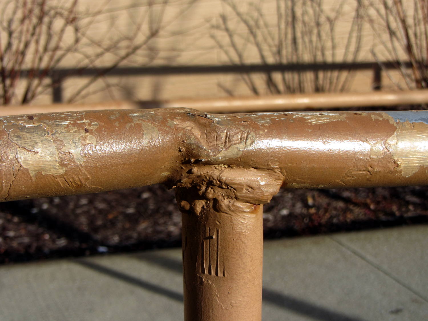
In all fairness, I don’t know how you’d weld a decent joint in a situation like that, without far more prep work than seems appropriate. There’s not much metal in those tubes for proper grinding and fishmouthing.
The handrail may not be long for this world: the bottom few inches of many posts have corroded to the vanishing point due all the salt applied to the pavement…
The LED mounting plate inside the sewing machine’s end cap sits 30° from the vertical axis of the needle. Even though the surface-mount LED emitters have a broad pattern, it seemed reasonable to aim them toward the needle to put the brightest spot where it’s needed.
The LEDs must have enough heatsinking to pull 2+ W out of the solder pads, so I figured I’d just epoxy them firmly to the mounting plate, rather than try to gimmick up a circuit board that would interpose a fiberglass slab in the thermal path.
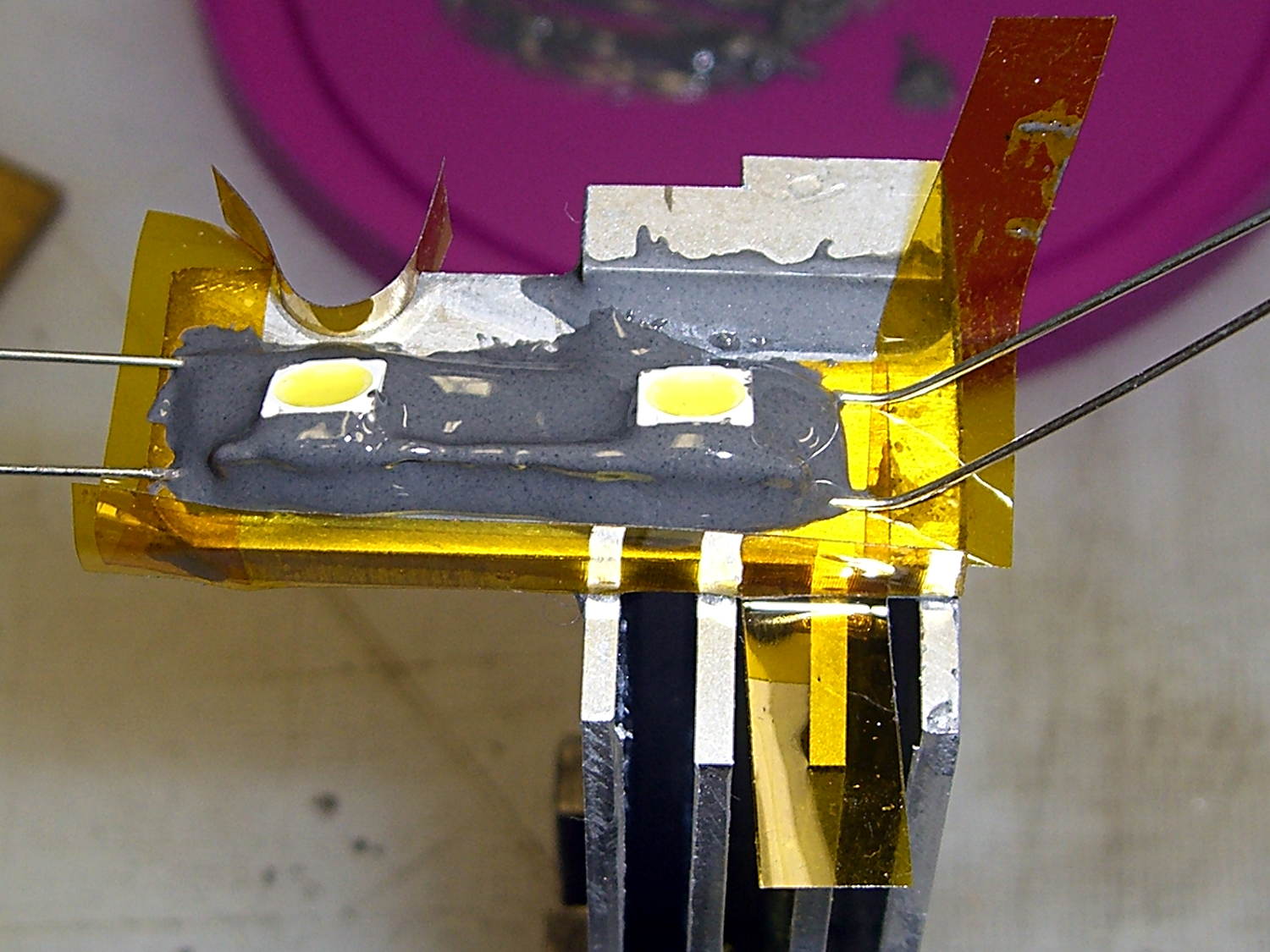
Combine those two requirements and you (well, I) get a wire fixture that provides both power and alignment:
LED mount – wire fixture
The LED body is 5 mm square, sin(30°) = 0.5, and the rear wire raises contact end by 2.5 mm. This still isn’t an exact science; if the center of the beam lands in the right time zone, that’s close enough.
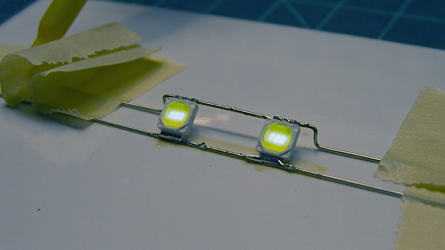
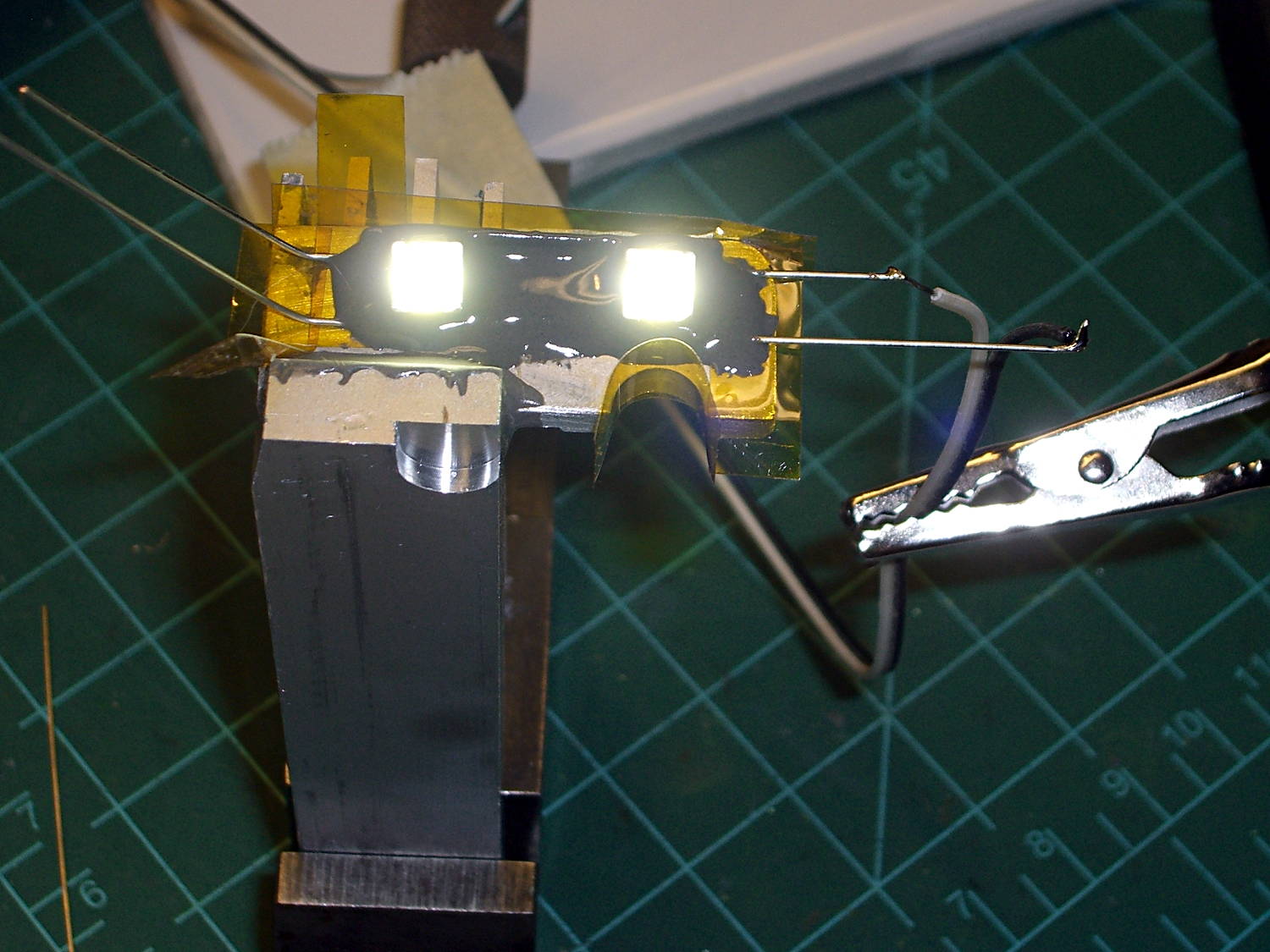
Testing the LED assembly at low current before entombing it shows the emitters have six chips in series (clicky for more dots):
LED mount – lighting test
The grotendous solder job follows my “The Bigger the Blob, the Better the Job” principle, modulated by the difficulty of getting a smooth finish on bare wires. Indeed, the first wires I painstakingly bent, set up, and soldered turned out to have an un-solderable surface, much like the header pins from a while ago. That hank of wire now resides in the copper cable recycling bucket; you’re looking at Version 1.1.
Two strips of Kapton tape under the ends of the wires hold them off the (scoured and wiped clean!) aluminum plate, with more tape forming a dam around the nearest edges:
LED mount – epoxy pour
Despite being steel-filled, JB Weld remains nonconductive, the epoxy-filled gap under the wires insulates them from the plate, the wires aren’t shorted together, and there’s a great thermal bond to the heatsink. Good stuff, that JB Weld!
A view from the back side shows the epoxy sagging over the wires before I added another blob:
LED mount – epoxy pour – rear
The LED assembly just sits there, without being anchored, until the epoxy cures. The epoxy remains thick enough (in the rather chilly Basement Laboratory) so that it doesn’t exactly pour, can be eased into place without too much muss & fuss, and stays pretty much where it’s put.
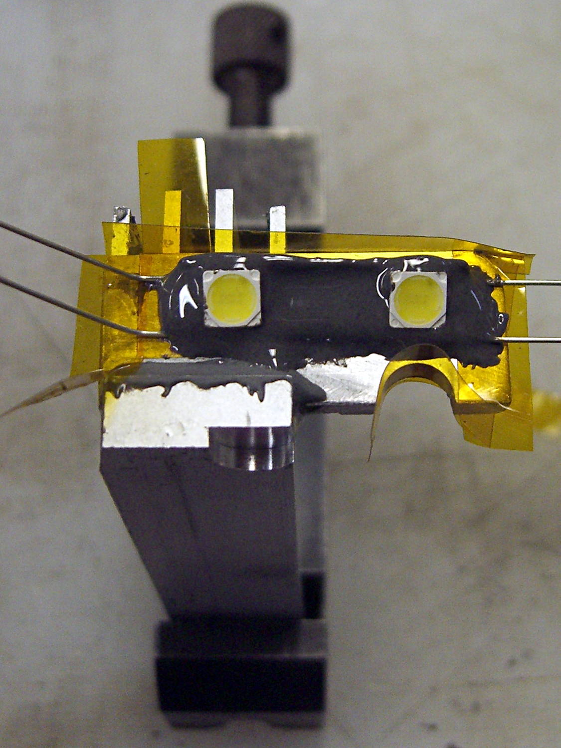
After the epoxy stiffened a bit, I gingerly positioned stranded wires not-quite-touching the LED wires and applied a dot of solder to each. Powering the LEDs from a bench supply at 500 mW each took the chill off the heatsink and encouraged proper curing:
LED mount – heated epoxy cure
Fast forward to the next day, return the heatsink to the Sherline, and drill a hole for the power cable. It’s centered between the wires in Y and between the fins in X, which is why I couldn’t drill before mounting the LEDs:
LED mount – drilling cable hole
It’s not like I’m building this from any specs…
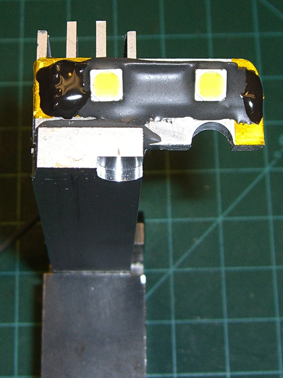
Trim the wires, solder the cable in place, cover the wire ends & joints with JB KwikWeld epoxy, and it’s done:
LED mount – final epoxy
With the LEDs running their 230 mA rated current, the entire heatsink gets pleasantly warm and the mounting plate isn’t much warmer than that. I loves me a good JB Weld job…
However, I suspect they’ll shine too brightly at full throttle, which means an adjustable power supply looms on the horizon…
In the quest for More Light around the Kenmore 158’s needle, I’m replacing the pair of 10 mm LEDs with a pair of 21 V / 115 mA = 2.5 W surface-mount emitters that require a good heatsink. Because the heatsink must mount inside the sewing machine’s end cap, there’s not much air circulation: when sizing the heatsink, I figure that nothing exceeds like excess.
There doesn’t seem to be any way to measure the available space inside the hinged end cap, so the plan is to fit the largest possible heatsink, run it for a while, and then build a smaller (and presumably less awkward) heatsink based on those measurements.
I sawed a slice off an aluminum heatsink harvested from a junked PC, wrapped masking tape around it, and filled it with machinable wax to prevent the fins from chattering:
Heatsink filled with machinable wax
Pouring the wax into a cold heatsink worked about as poorly as you’d expect, so I held the heatsink over the stove burner, slowly remelted the wax into the bottom of the fins, and topped it off with more wax from the pot. I’m almost certainly using too little fire; the stuff melts at a bit under 300 °F and doesn’t really get liquid at any temperature I was comfortable with. The double boiler we use for candle wax won’t get nearly hot enough.
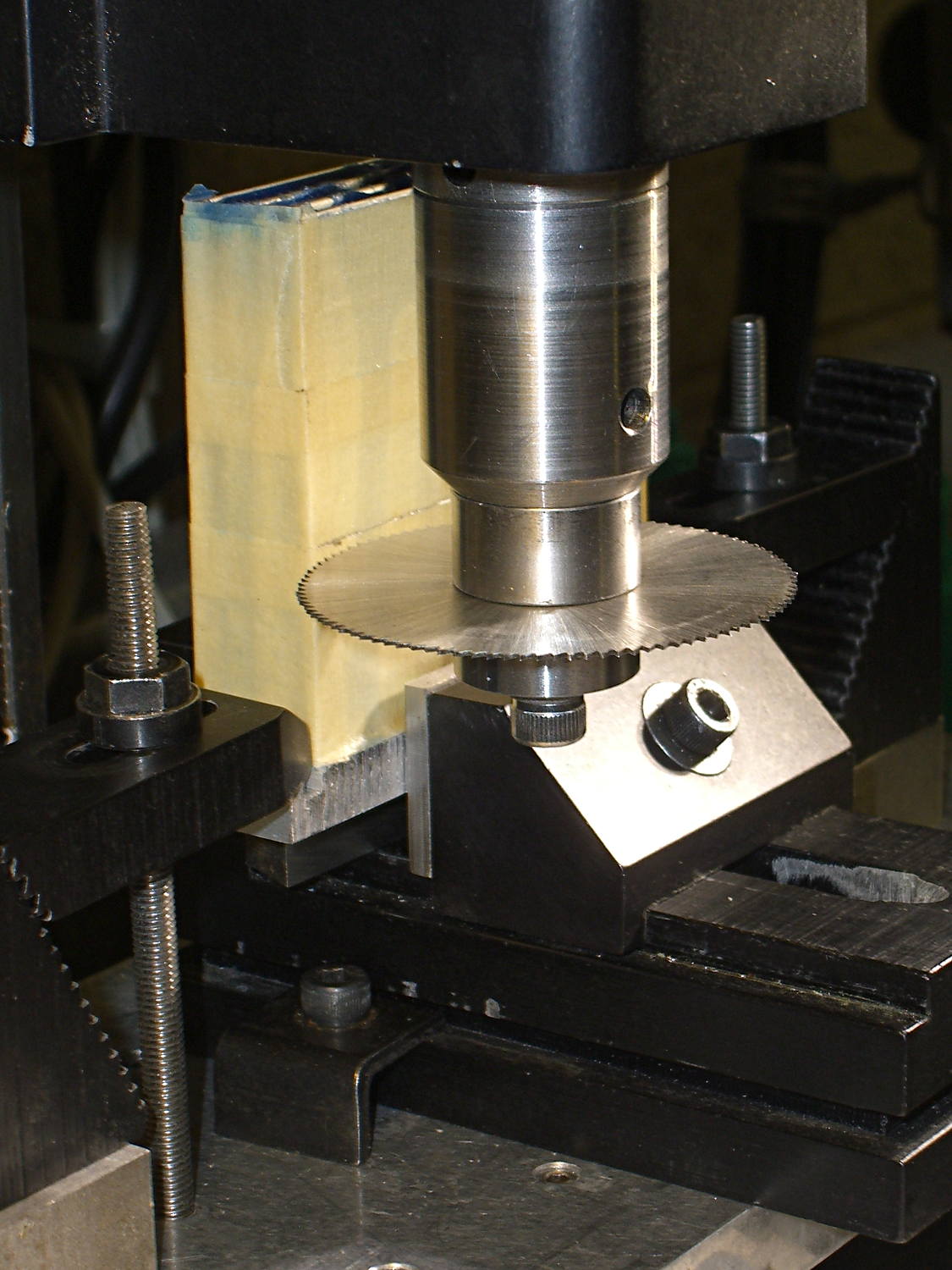
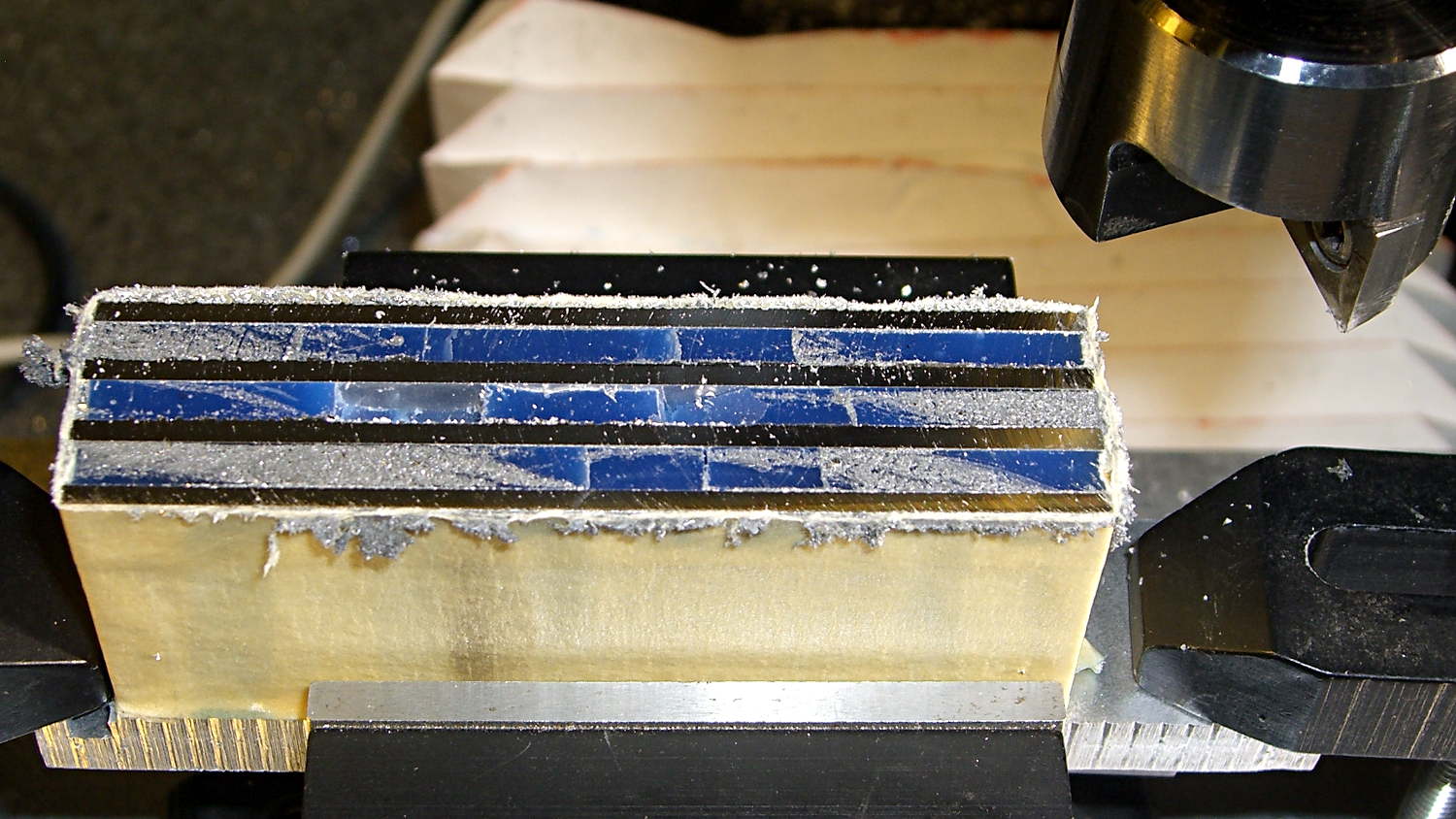
Clamped into the Sherline’s vise, it’s obvious that the slitting saw won’t quite reach all the way through:
Heatsink – slitting saw setup
I figured the height by working backwards from the outside of the end cap and forward from the bulkhead at the end of the arm. As it turned out, the middle fins fit and the outer two didn’t, but it was surprisingly close. The length turned out to be spot on, which is the sort of coincidence that tells me I’m on the right track. This is not an exact science.
One cut along the front, another along the rear, and the fins popped right off:
Heatsink – cut detail
Those aren’t broken teeth on the blade, they’re just loaded with wax and aluminum dust.
My plan to secure the heatsink to the sewing machine by repurposing two convenient screws was foiled by the lower screw: it’s too short and sports a fine 6-40 thread. Not only does my heap lack 6-40 screws, Eks doesn’t have any, either; I would have lost big money on that bet.
Brownell’s has a fillister-head screw assortment including 6-40 threads, so that problem will Go Away in short order, but they’re out of stock at the moment. My other Brownell’s assortment (which they no longer carry) includes 5-40 screws, but …
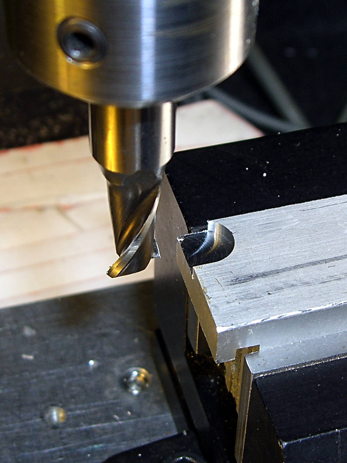
This being a prototype, I simply milled a recess to accommodate the offending screw head:
Heatsink – screw head clearance slot
The upper screw originally held the incandescent lamp socket in place and will be long enough to hold the heatsink.
In there somewhere, the ragged bandsawed edge on the far side got itself milled smooth.
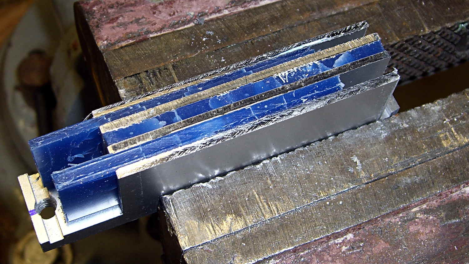
Some trial fitting showed the two outer fins must be 2 mm shorter to fit inside the end cap, so the finish on those isn’t nearly as nice:
Heatsink – removing machinable wax
That shows the machinable wax on its way out of the fins, urged along by whacking the ends with a wooden stick. The wax doesn’t adhere to the aluminum and leaves a clean surface, although I’m sure I should scrub it down with solvent to remove any residue.
A bit of paper-doll cutout work provided a shape for the plate that will hold the LEDs, then some bandsaw and hand-filing and milling trimmed it to fit. The heatsink has a slot along the edge, barely visible at the right end of the previous photo, so I hand-filed a rabbet in the plate to let it sit flat against the bottom of the slot and the end of the fins.
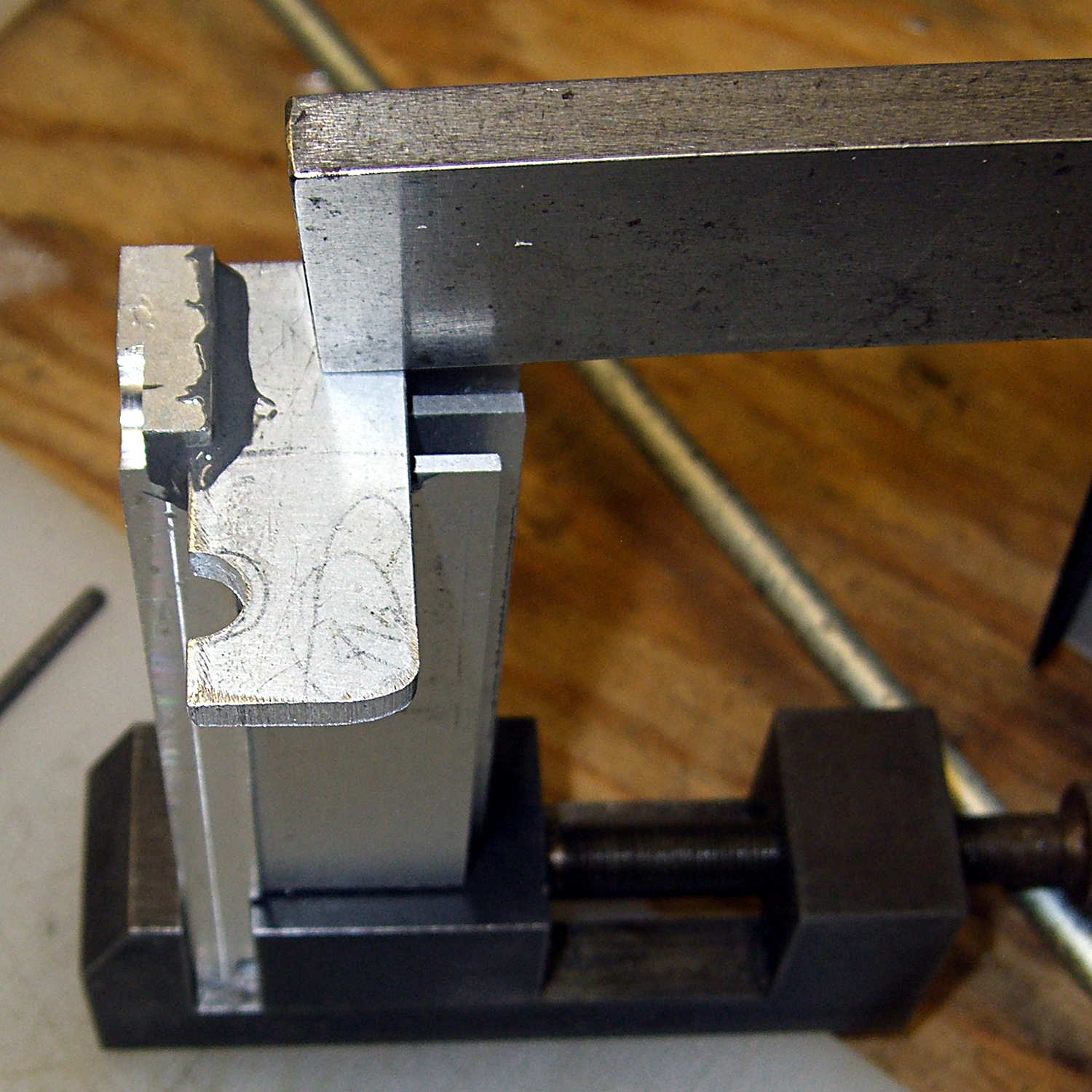
Steel-filled epoxy (good old JB Weld) secures the plate and provides good thermal transfer. The steel bar holds the plate against the fins while the epoxy cures:
Heatsink – epoxying LED mount
After some iterative abrasive adjustment on the belt sander, the assembly just barely fits inside the end cap. This view looks through the bobbin access hatch opening in the bed:
Heatsink – endcap trial fit
The two outer fins hit various mold sprues / vents / protrusions inside the cast (!) end cap. I think the next version will have three fins, as the cap rides right against the outer fin; the abrasive adjustment came into play on that fin and the end of the LED plate.
The plate could be a bit longer, but let’s see how this one works out.
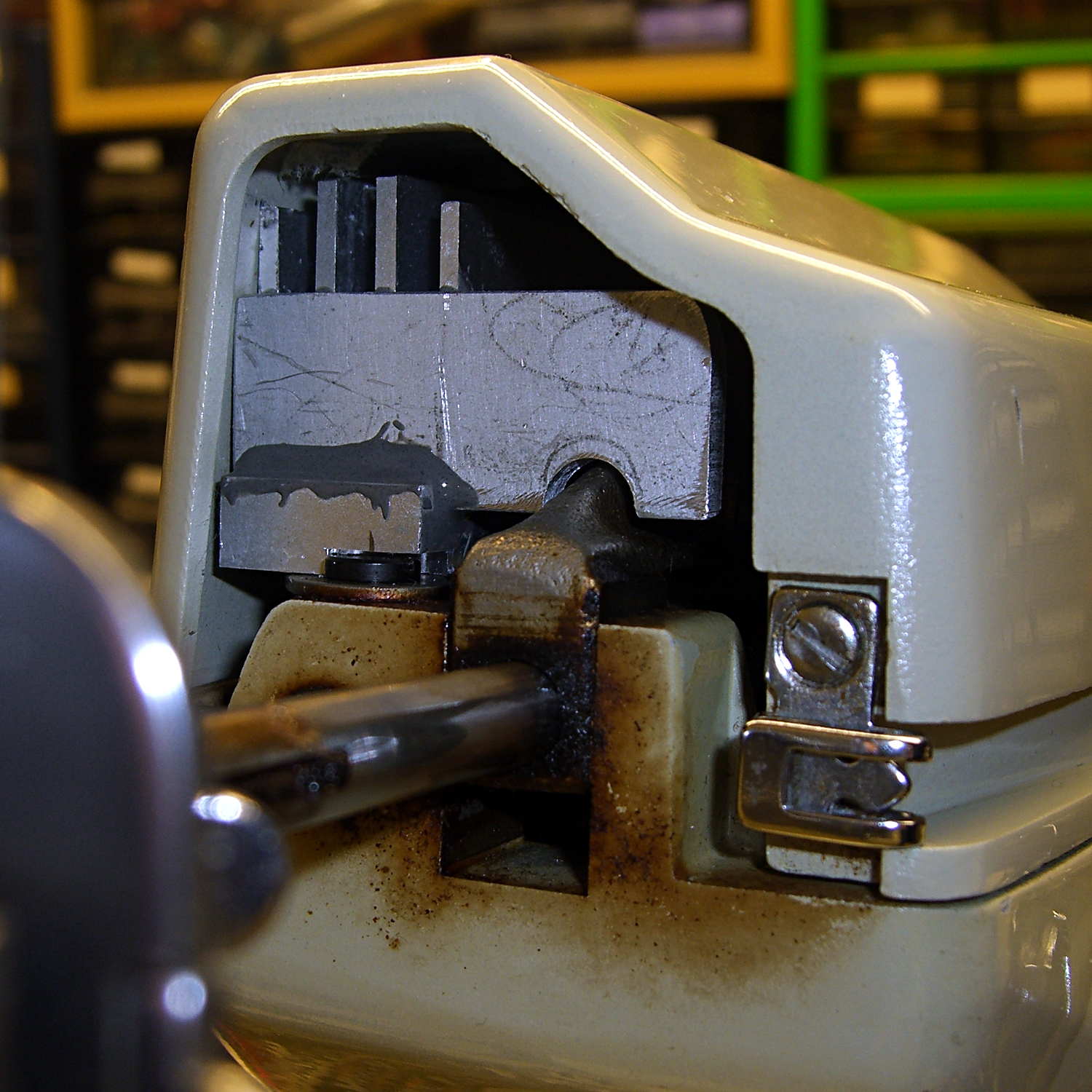
The notch just barely clears the arm that moves the needle sideways during zig-zag stiches. The rectangular joint guides the arm left-to-right (vertically in this image), but doesn’t slide up-and-down. I think it’s as far out as it’ll ever get, but, again, this is a prototype.
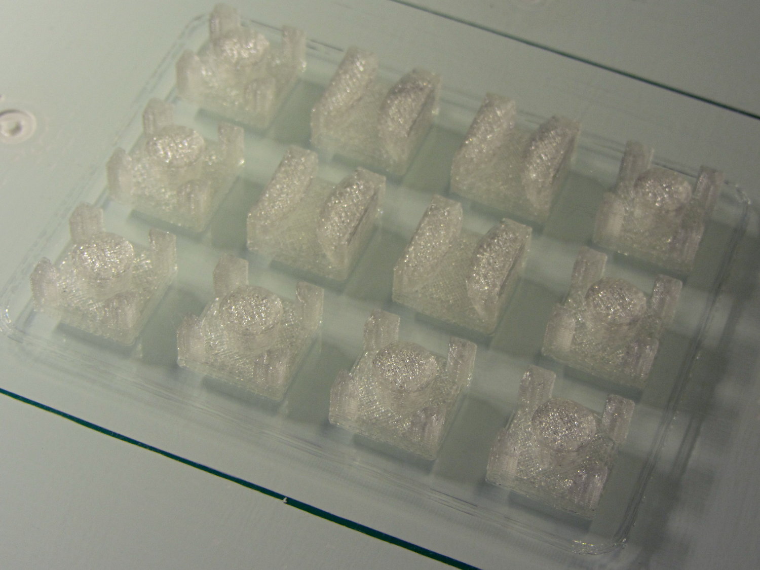
Back when I started fiddling with 3D printed chain mail, the whole process from model to plastic worked wonderfully well. That continued with the larger sheets, but now, occasionally, the OpenSCAD model would produce weirdly sliced links. Depending on nothing repeatable, some links wouldn’t bridge correctly: the thread paths in the bottom layer across the gap would mysteriously stop just short of one pillar, return to the start, and leave an unsupported shelf that would, of course, fall into the gap.
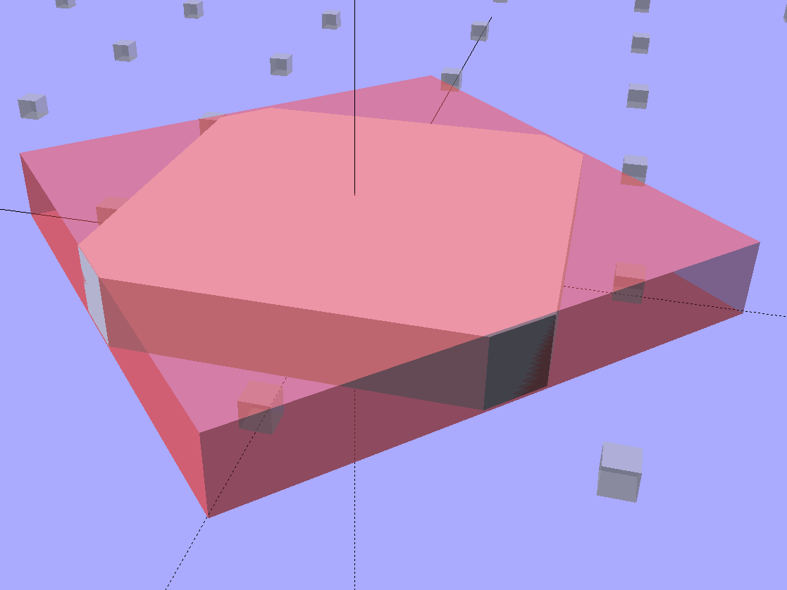
Shortly before Christmas, I managed to get a consistent failure that manifested differently: upon loading the STL file, Slic3r would quietly perform dozens of automatic corrections that (sometimes!) produced bizarrely distorted results. Feeding a failing model into Meshlab showed an irregular assortment of “self intersecting faces”, highlighted in red:
Chain Mail Square Armor – open – 2×2 – Meshlab self-intersecting faces
Although all four outer links in that image come from the same OpenSCAD module with identical sizes, they don’t all exhibit the same problem in the (nominally identical) faces on each of their four corners. In fact, those faces come from the intersection of two square slabs, carefully sized and positioned to avoid creating coincident planes:
Chain Mail Link – Outer shape
The central opening comes from a similar, slightly smaller, intersected-squares shape, but all four interior corner faces in each link show that they’re self-intersecting.
The STL looked fine in Meshlab, except for the highlit self-intersecting faces, so the geometry seemed OK.
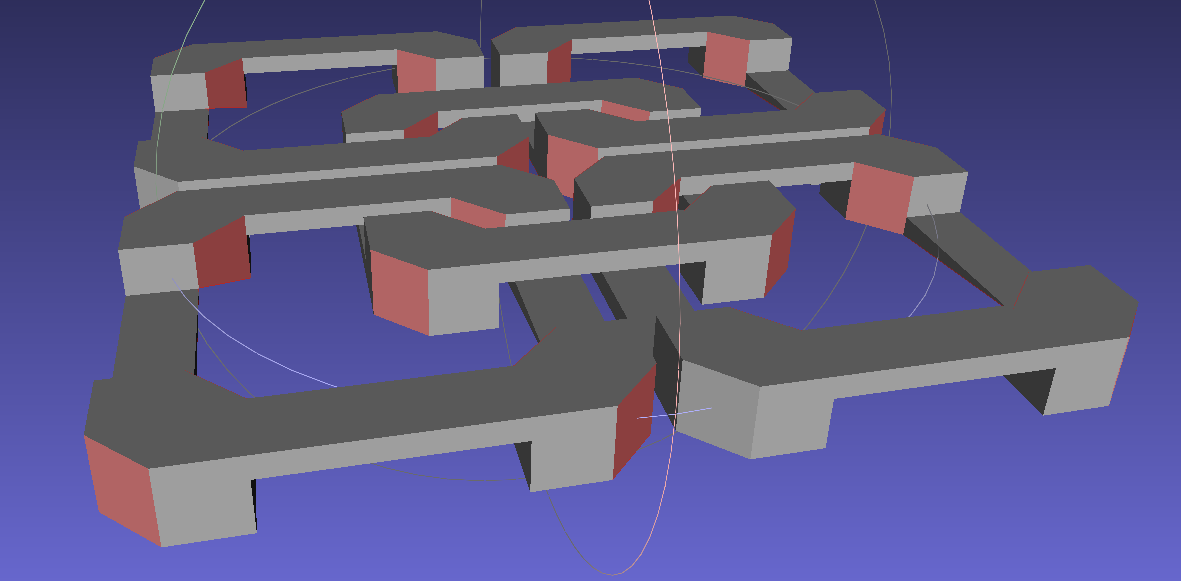
When Slic3r autocorrected the “problems”, it apparently removed one vertex on the bottom surface of each bar, deleted the triangles connected to that vertex, then repaired the mesh to produce a delightfully symmetric pattern:
Chain Mail Square Armor – open – 2×2 – Slic3r corrections
Although the links are resolutely symmetric, Slic3r seemed happy with the identical vertices at the other end of the bar.
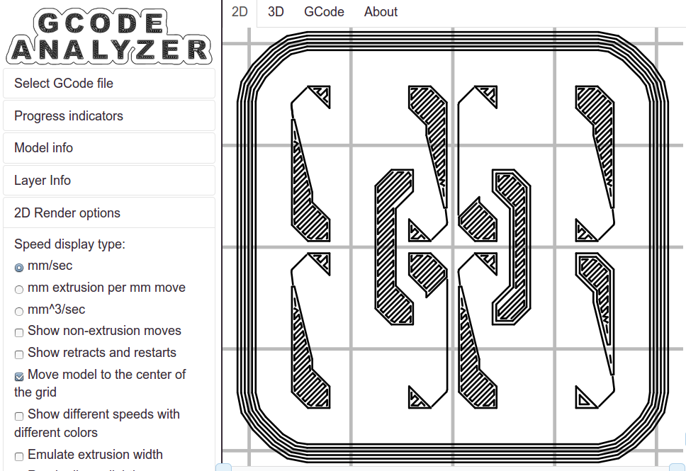
Unfortunately, the resulting G-Code won’t produce good links:
Chain Mail Square Armor – open – 2×2 – first layer G-code visualization
So, shortly before Christmas, I filed an issue on OpenSCAD’s Github repository.
The ensuing discussion showed that Meshlab flags faces as “self intersecting” when they have different vertices, even if their values are numerically equal, as well as vertices that differ by teeny amounts. Slic3r applies slightly different criteria to vertices & faces when it automagically corrects “problems” in the STL file, so that Meshlab may:
Highlight faces that don’t bother Slic3r
Apply the same highlight to faces that cause horrible problems
I don’t profess to understand much of that and may have the details wrong, but, apparently, OpenSCAD formerly used quantized coordinates that ensured all vertices within a tiny volume would have the same numeric value. In particular, all three faces that meet at a common point would, in fact, have numerically equal coordinate values for that point. The STL file format consists of a list of separate triangles, each with three coordinates for each of the three axes, and (without quantization) it was entirely possible for each of the three triangles with a common point to have three very slightly different positions for that point.
In theoretic terms, quantized coordinates cause horrible problems during geometric manipulation, because numeric values that aren’t exact can make repeated transformations come out wrong; running an object through a transformation and it’s inverse might not yield an object identical to the original one.
In practical terms, it seems that slicers and STL repair algorithms can reach incorrect conclusions based on minute differences produced by floating-point operations and numeric-to-text conversions. Those differences depend on slight changes in position, rotation, and size, so doing anything to the model produces completely different results.
That notwithstanding, the day after Christmas brought a new OpenSCAD version that uses quantized coordinates. A bit of rummaging in the source shows that the 3D grid (defined in src/grid.h) isn’t all that coarse:
const double GRID_FINE = 0.00000095367431640625;
STL files don’t carry units, so that could be in either millimeters (the Slic3r / RepRap convention) or inches (Sketchup, but we won’t go there). It’s exactly 1/10242, in case you were wondering, which produces a 5% speedup in the geometry engine compared to the more human-readable 1/10002.
With that commit in hand, all the chain mail links slice perfectly again.
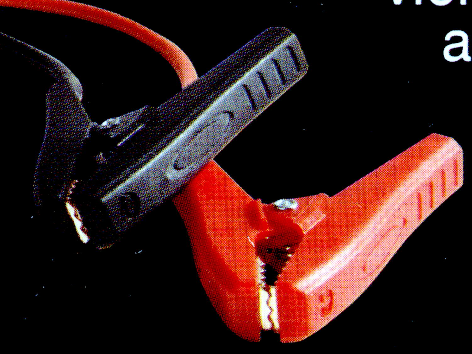
The Sienna now spends all its time sitting outdoors in an apartment parking lot and gets even less driving (hence, battery-charging) time than we used to give it. Fortunately, Santa being my kind of guy, our Larval Engineer received a Pilot InstaBoost jumpstarter, which is basically a 10 A·h / 40 W·h lithium battery with husky plug & socket connectors, a pair of 10 AWG wires, and big alligator clamps. The package claims a 400 A peak discharge rate, but the tiny inscription on the back of the case reports 200 A; either of those seems mmmm somewhat optimistic to me.
The customer reviews suggest that the plastic battery clamp handles feature a crappy hinge joint which disintegrates under moderate stress on a cold winter night, firing the spring into the nearest snowbank and rendering the clamp completely useless. The joint consists of a plastic post on each side of the inner handle that protrudes into a hole in the outer handle:
Battery Clamp – original joint
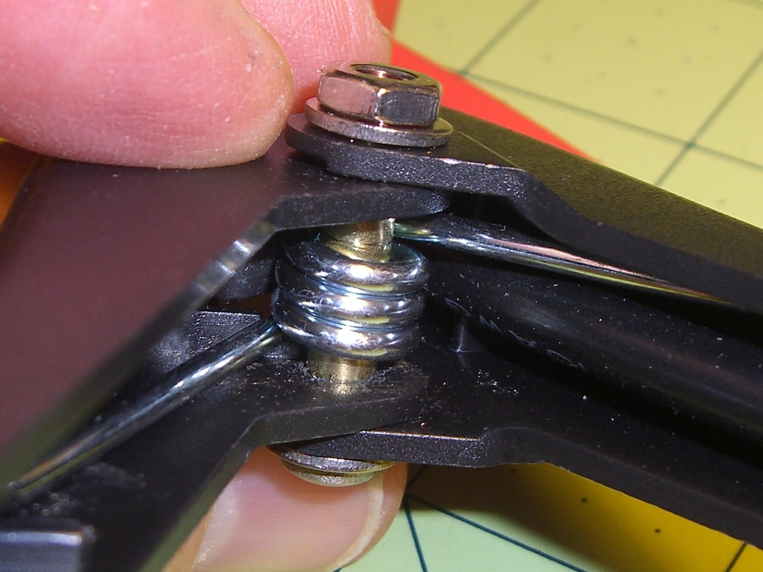
I assigned her some Mandatory Quality Shop Time to improve the joint. She found some brass tubing that fit the existing hole and cut two pieces to length:
Battery Clamp – cutting brass tube
A 1 inch stainless screw was just barely long enough (that’s Loctite Red in the nut), but the end result certainly looks durable enough:
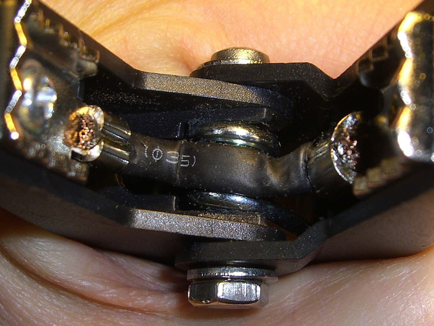
Apart from that, the clamps look pretty good. There’s even a husky braid between the two jaw pads, ensuring at least one reasonably low resistance joint to the battery post:
Battery Clamp – jaw strap
With a bit of luck, we’ll never know how well it works as a jumpstarter. She can use the USB port to keep her phone charged, which may provide enough motivation to keep the thing topped up and ready for use…
[Update: two days after this post went live, someone found it by searching for: