Ed Nisley's Blog: Shop notes, electronics, firmware, machinery, 3D printing, laser cuttery, and curiosities. Contents: 100% human thinking, 0% AI slop.
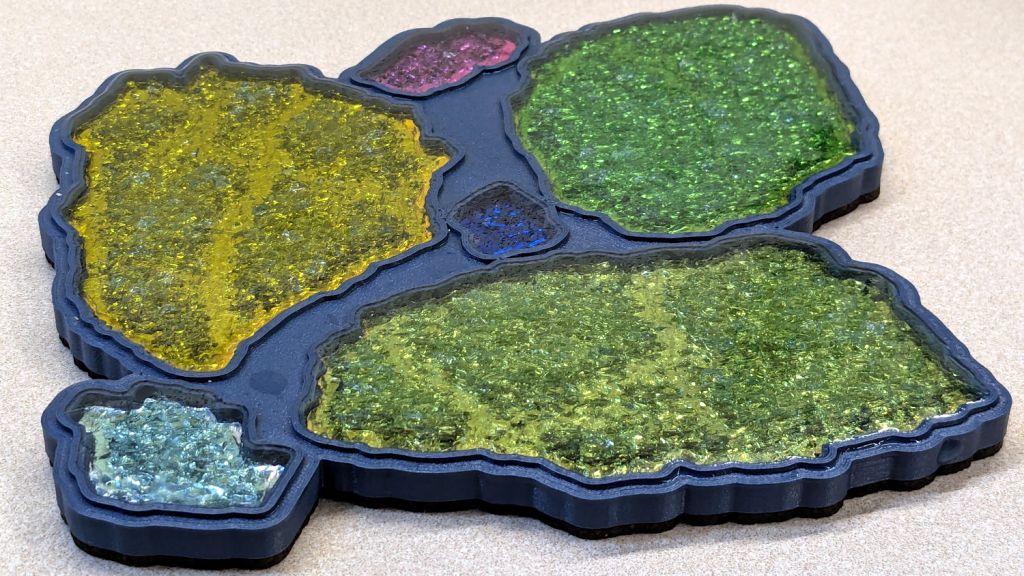
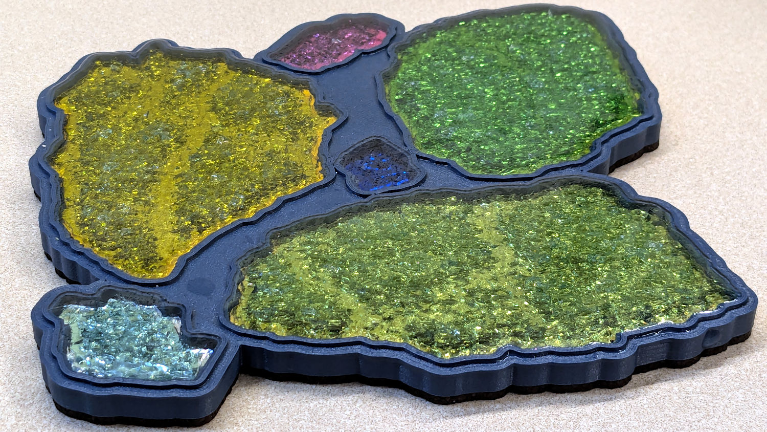
Although the larger fragments were still holding together when I laid them in their recesses, they apparently consist of several sub-fragments with larger continuous cracks letting the epoxy flow / ooze inside.
Now that I know what to look for, the original picture also shows them, albeit less distinctly:
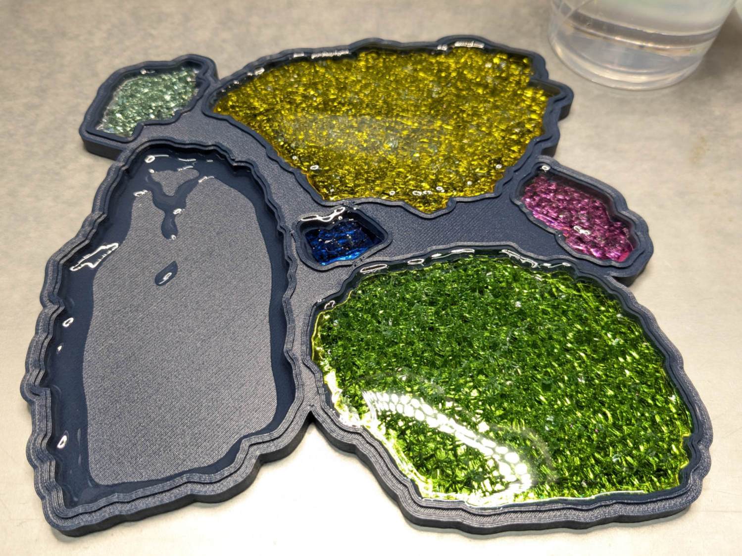
Printed Fragment Coaster 165mm – overview
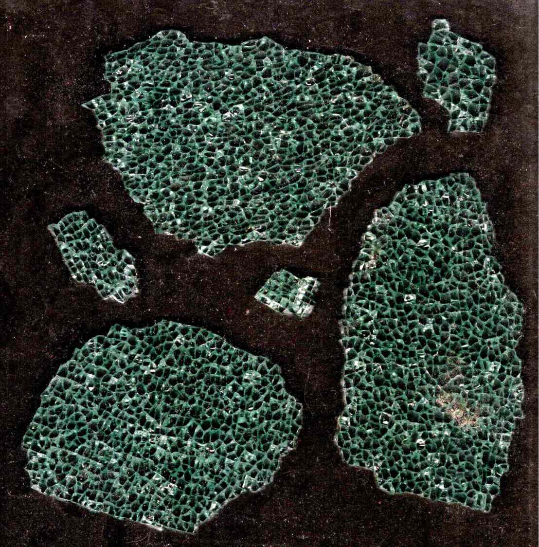
They’re not obvious in the scanned image of the fragments, although I could convince myself I see some:
Fragments 165mm square – scan sample
The many smaller fragments I’ve been turning into coasters probably separated from similar large chunks along such cracks, which is why I’ve never seen rivers of crack before.
Apologies if you arrived here expecting a tirade concerning the drug trade … :grin:
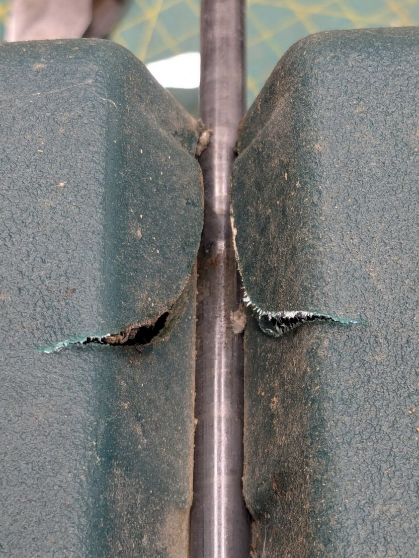
The cart in Mary’s Vassar Farm plot returned in need of repair:
Garden Seat – fractured body
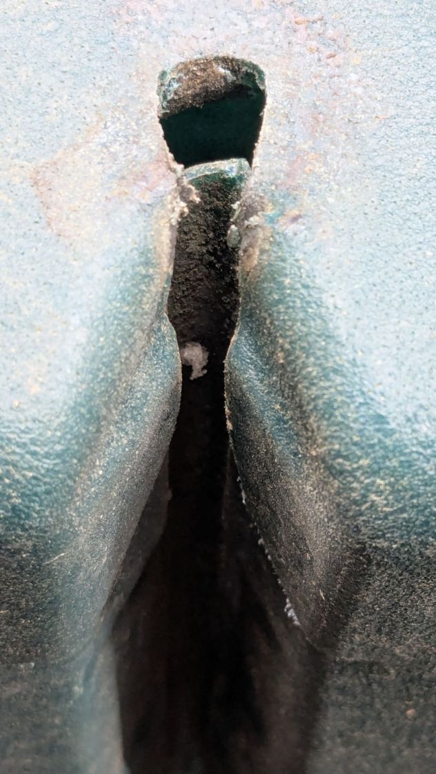
Those fractures near the end of the axle let the axle erode the side wall:
Garden Seat – eroded body
This will obviously require some sort of reinforcement on the body holding the axle, but the first challenge involved getting the wheels off the axle:
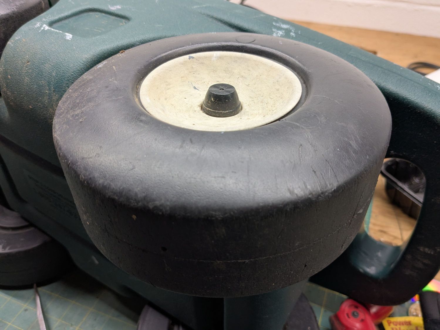
Garden Seat – axle cover
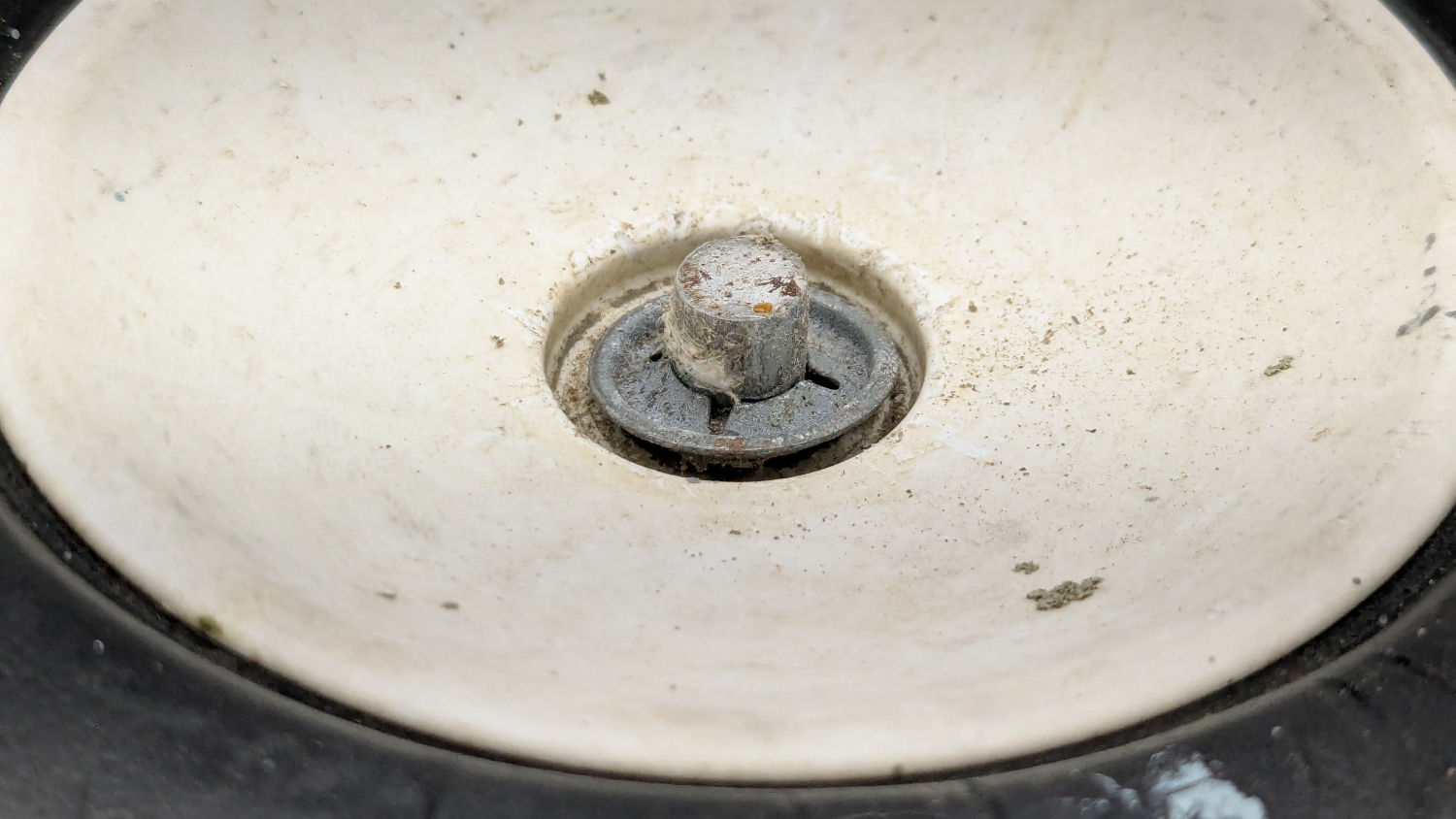
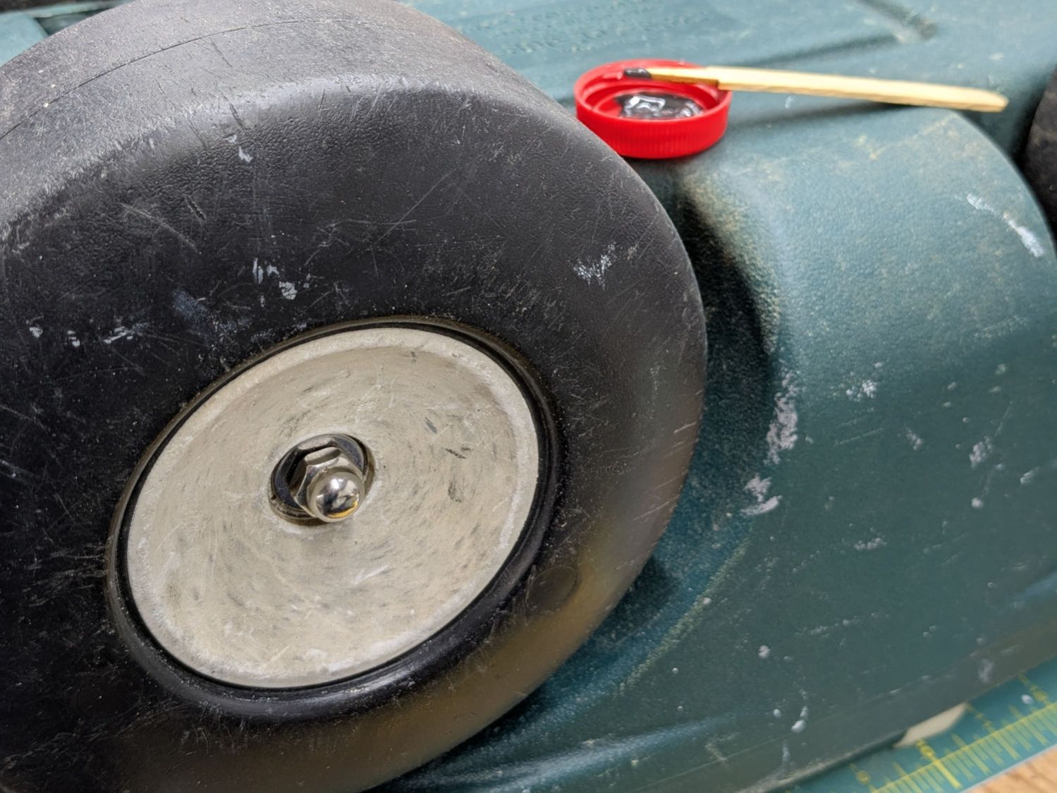
Some brute force revealed the hub covers snapped over an install-only locking fastener:
Garden Seat – axle retaining clip
More brute force cut those fasteners (a.k.a. star-lock washers) to get the wheels off the axles.
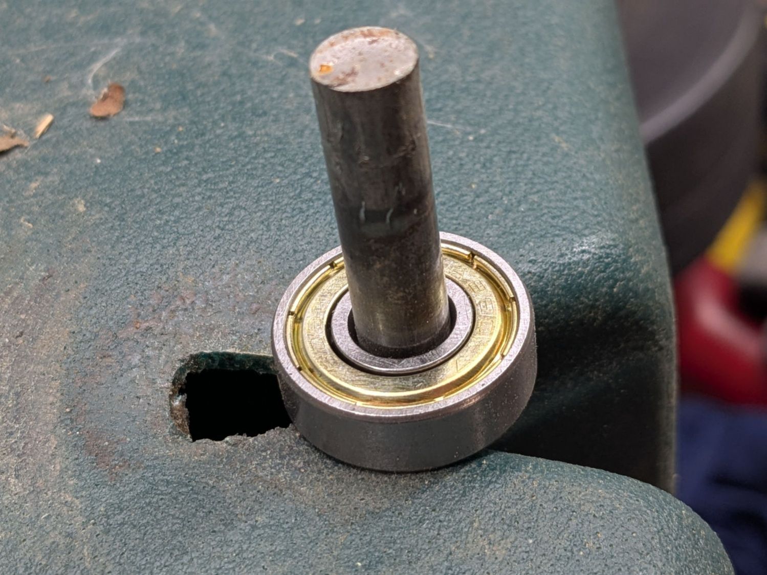
While contemplating the situation, a box of 606 bearings (as used in the PolyDryer auto-rewind spindles) failed to scamper out of the way and produced a victim fitting perfectly on the 8 mm axle:
Garden Seat – bearing idea
I regard such happenstance as a message from the Universe showing I’m on the right track. The alert reader will note the axle should not rotate, but does sport scars showing it’s done some turning in the recent past, so the bearing may not be a completely Bad Idea™.
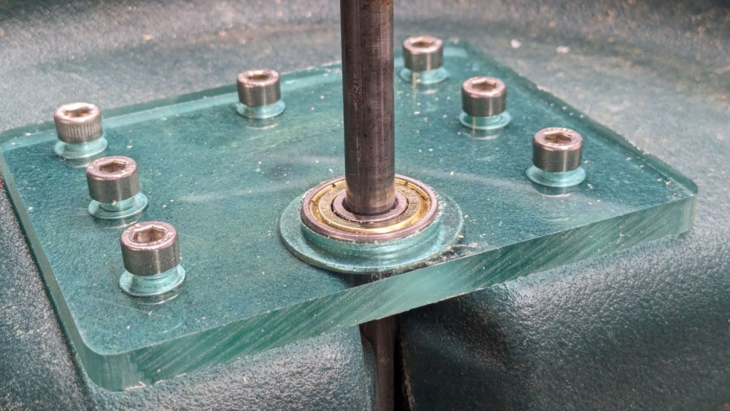
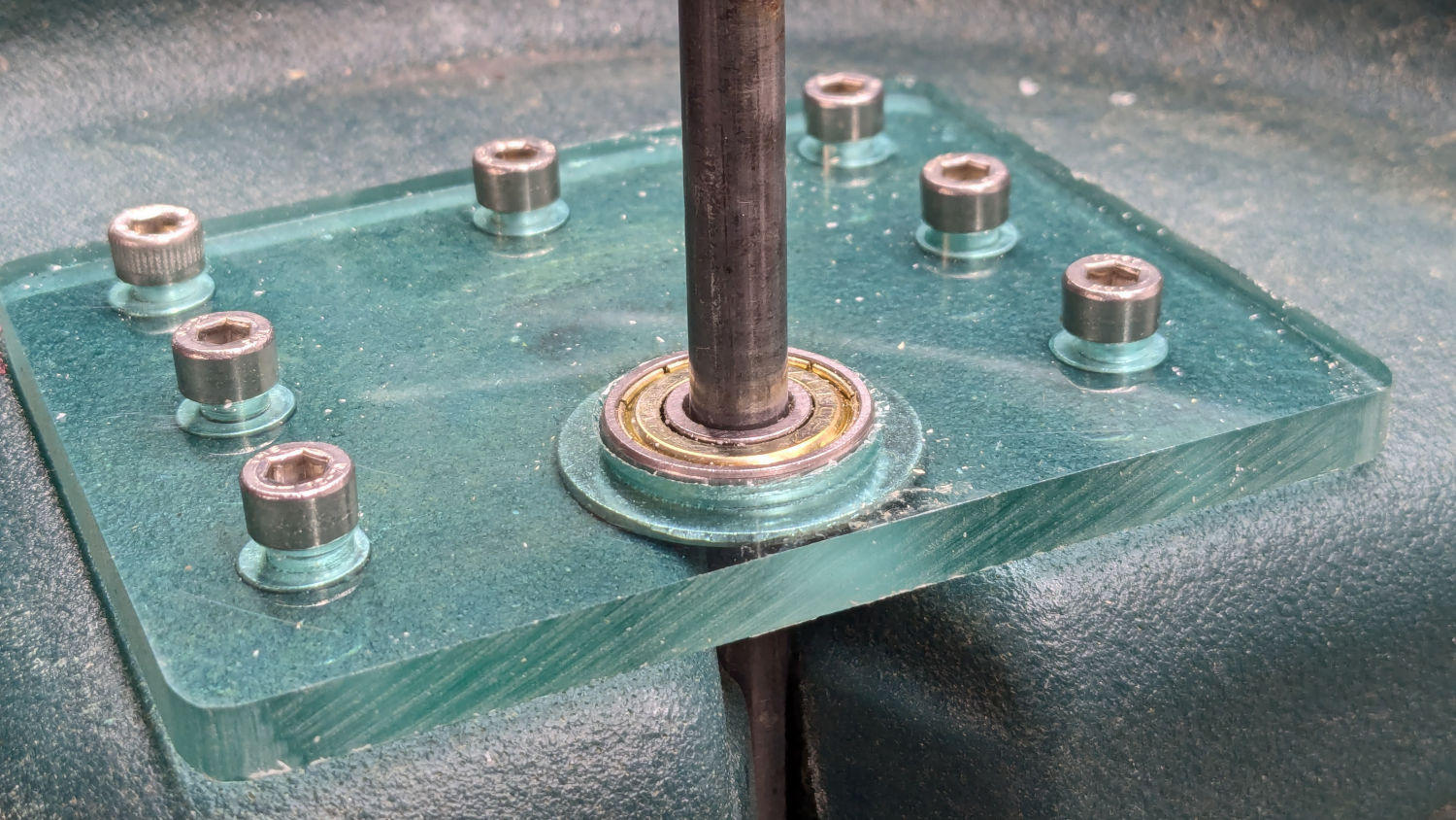
Finding a Lexan snippet exactly as thick as the bearing suggested bolting a plate across the side of the body to support the bearing, like this:
Garden Seat – reinforcing plate installed
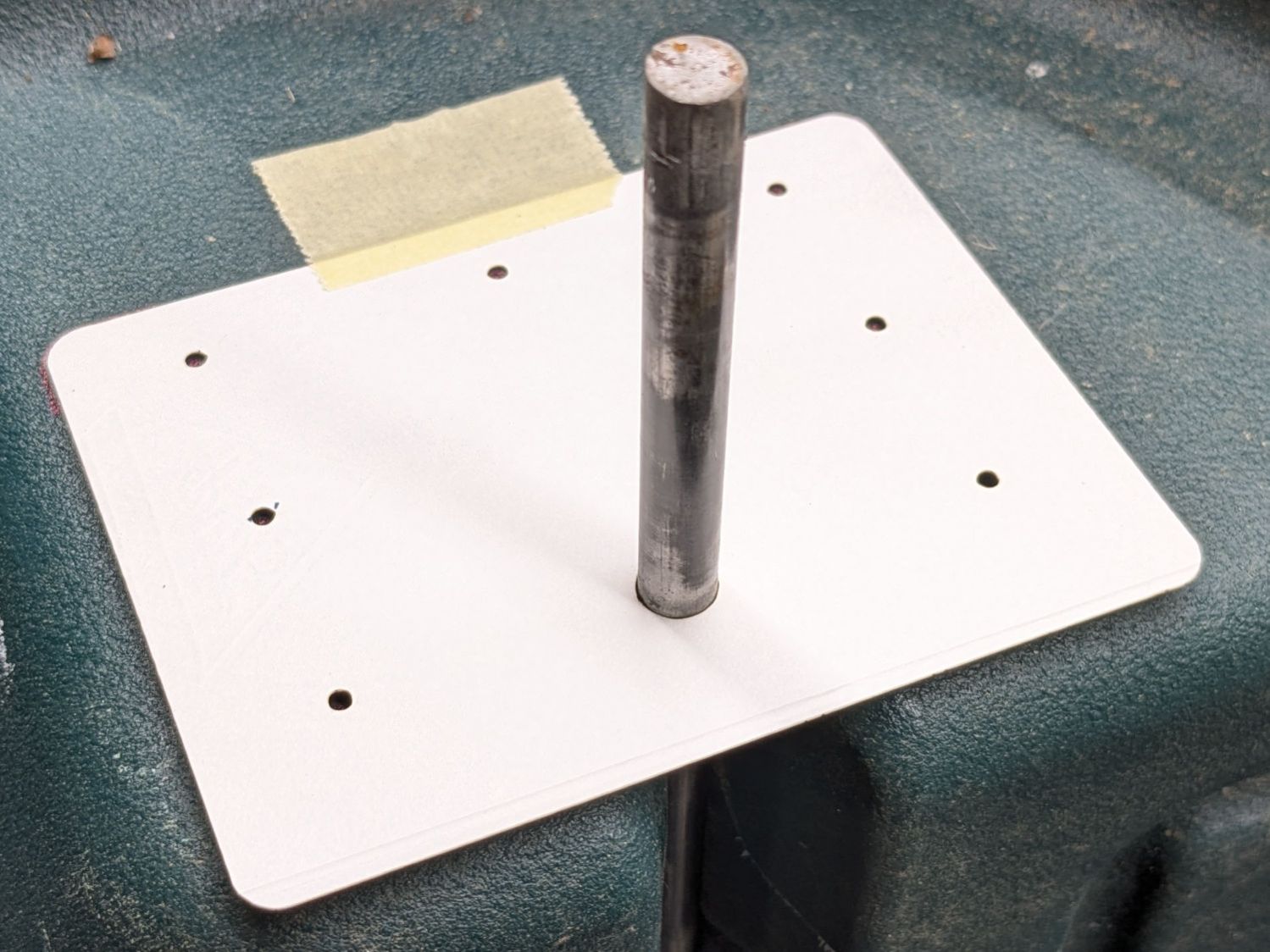
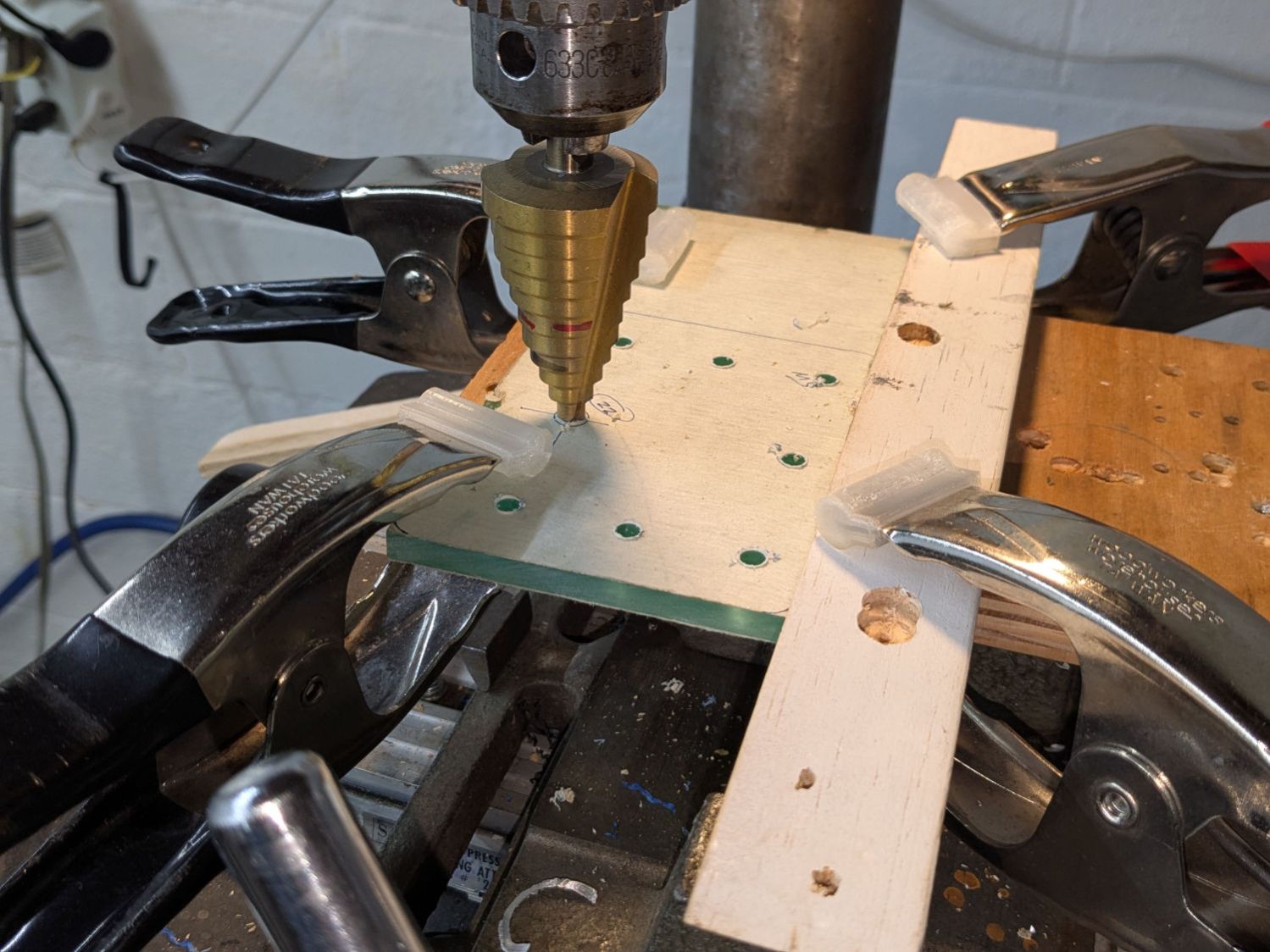
Some layout work in LightBurn produced a template to mark the body for hand-drilling the holes:
Garden Seat – drill marking template
In retrospect, that was a mistake. I should have:
Laser-cut an MDF sheet to make a drill jig
Drilled one hole and inserted a screw
Drilled the rest of the holes in exactly the right places
Instead, three of the holes in that nice Lexan sheet ended up slightly egg-shaped to adjust for mis-drilled holes in the body.
I squeezed 5 mm rivnuts into whatever fiber-reinforced plastic they used for the body, which worked better than I expected. They’re intended for sheet metal, so I set the tool for 5 mm compression and they seem secure. I hope using plenty of screws across a large plate will diffuse the stress on each screw.
In this situation, I regard JB KwikWeld epoxy as “removable with some effort”, as opposed to the destruction required with those star-lock washers. High-strength Locktite might also be suitable, but I do not anticipate ever having to remove these again for any reason and do not want the nuts to fall off in the garden.
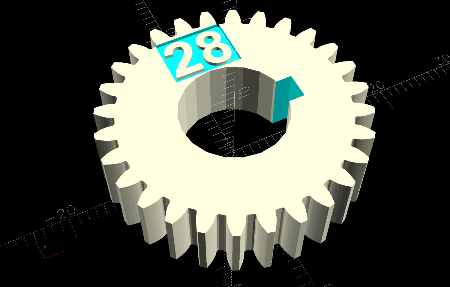
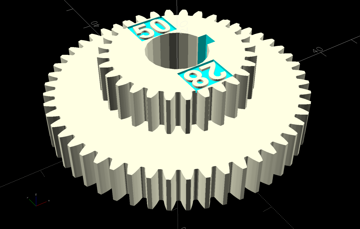
The labels now snuggle closer to the shaft and (barely) fit on smaller gears:
Mini-lathe stacked change gears – 28T – solid model
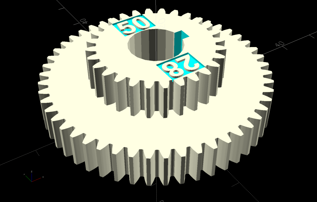
The stacked B-C gears for the jack shaft work as before, with both labels on the top gear:
Mini-lathe stacked change gears – 28-50T – solid model
The admittedly flimsy motivation for all this was to make a 28 tooth gear to cut a 0.9 mm pitch, thus filling an obvious hole in the gear table.
My collection of gears could do 21-60-81-50, but the 81 T gear collides with the screw holding the 21 T gear. Rearranging it to 21-50-81-60 showed the B-C gears exceeded the space available.
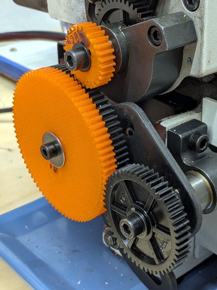
Because it’s all ratios and a 28 T gear is 4/3 bigger than 21 T, reducing the rest of the train by 3/4 should work. In fact, it produced a reasonable 28-80-81-50 chain:
Mini-lathe change gears – 28T installed
The fact that I do not anticipate ever needing to cut a 0.9 mm pitch has nothing whatsoever to do with it; that gear will surely come in handy for something.
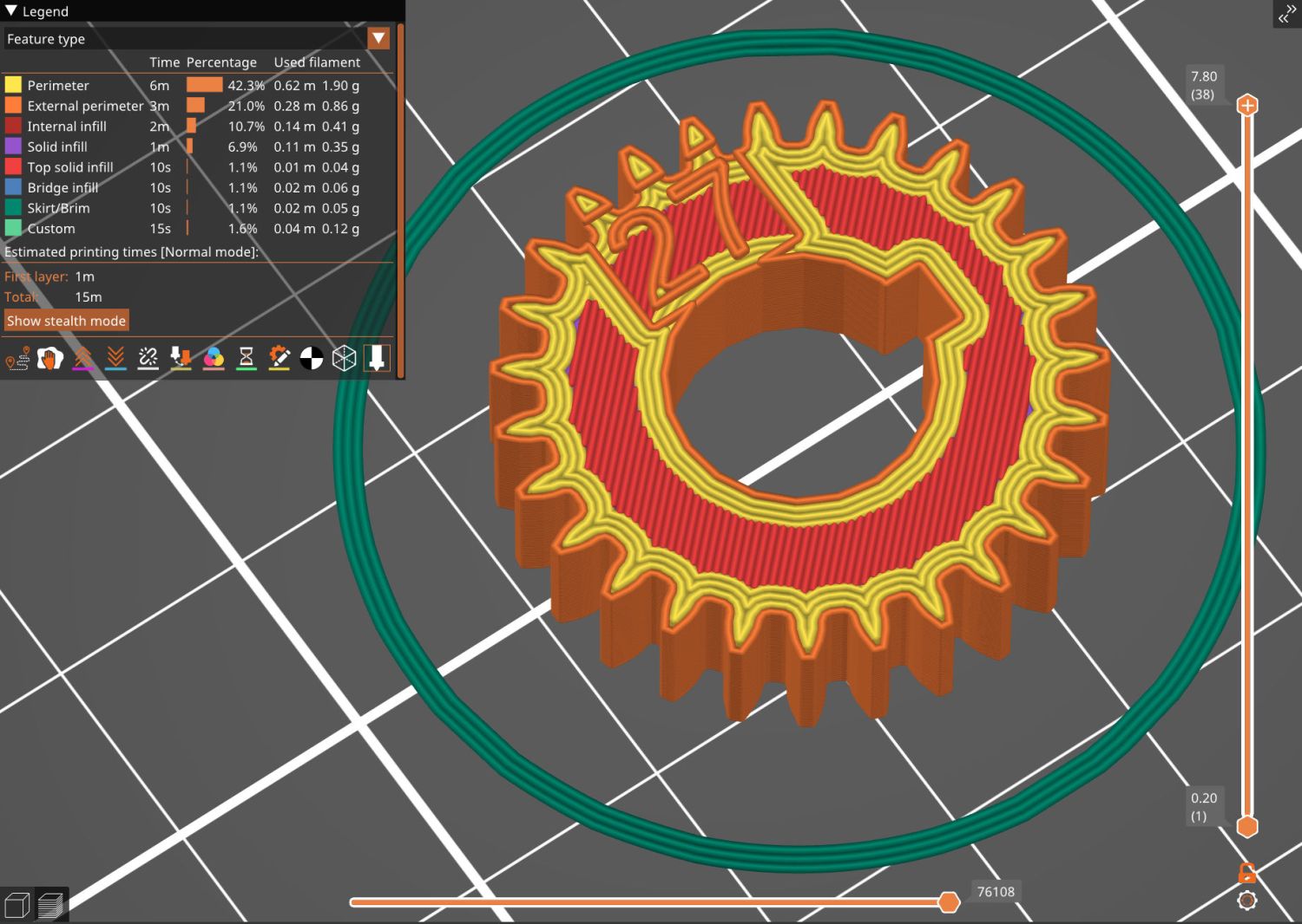
While I was at it, I made a 27 T gear, because 27 = 21 × 9/7:
This file contains hidden or bidirectional Unicode text that may be interpreted or compiled differently than what appears below. To review, open the file in an editor that reveals hidden Unicode characters.
Learn more about bidirectional Unicode characters
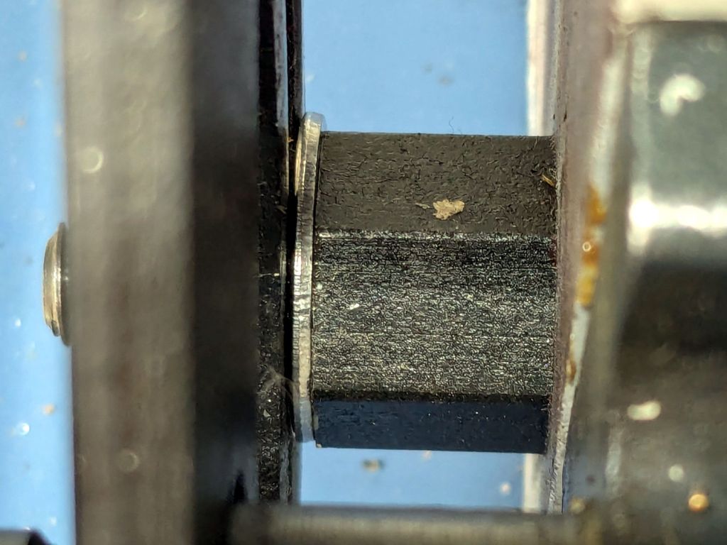
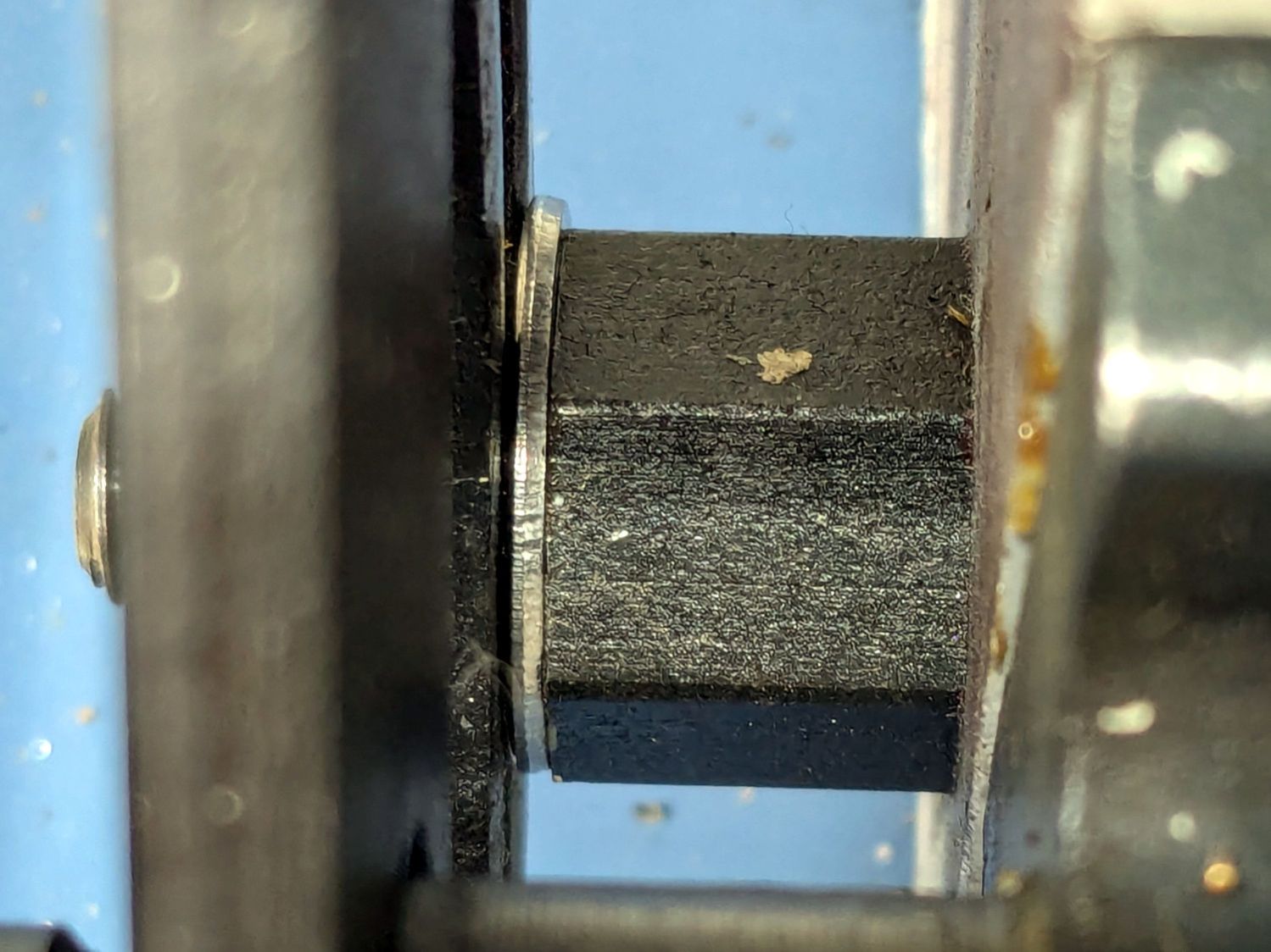
I intended to single-point a few turns on an 8 mm axle to ease running an M8-1.25 die over it, thus making a thread for a nut securing a wheel (about which, more later). This required selecting the change gears for a 1.25 mm thread pitch, the installation of which proved sufficiently awkward to give me the opportunity to discover a washer spacing the banjo just a little farther outward would improve the gear alignment:
Mini-lathe change gear banjo – shim detail
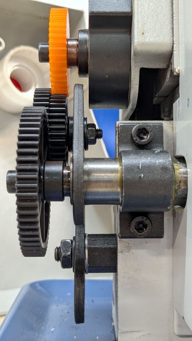
The overview shows how moving the whole banjo just a bit leftward better aligned black Gear B with respect to orange Gear A:
Mini-lathe change gear banjo – shim overview
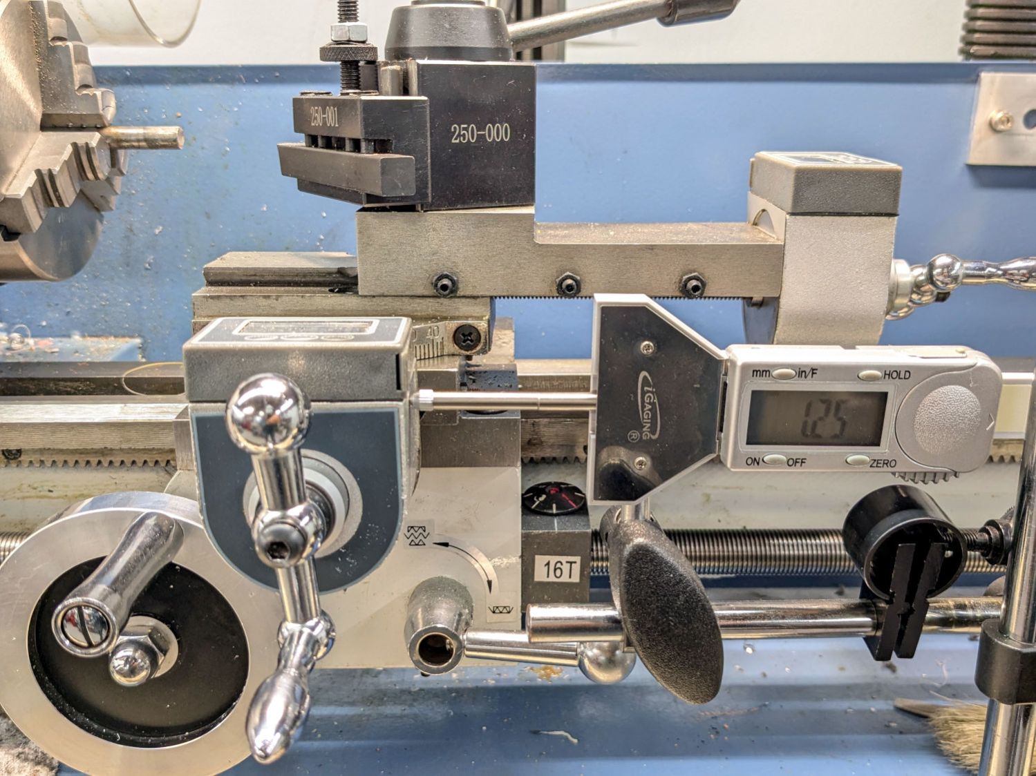
From A to D, a 1.25 mm pitch uses 42 40 45 60 tooth gears. The 42 tooth gear supplies the magic required to convince a hard-inch 16 TPI leadscrew to produce good-enough metric pitches.
In addition to the usual hassle, the main reason the process took so long is doing having to do it twice. After I swapped Gear C and Gear B on the jockey shaft in the middle, the leadscrew produced the correct 1.25 mm motion for one turn of the chuck:
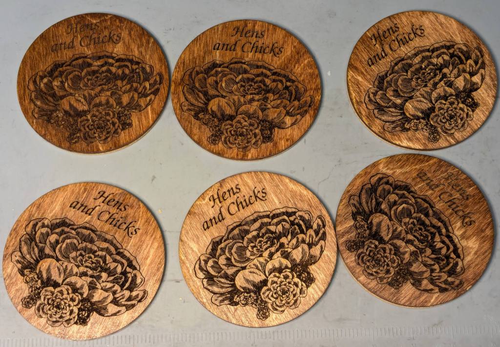
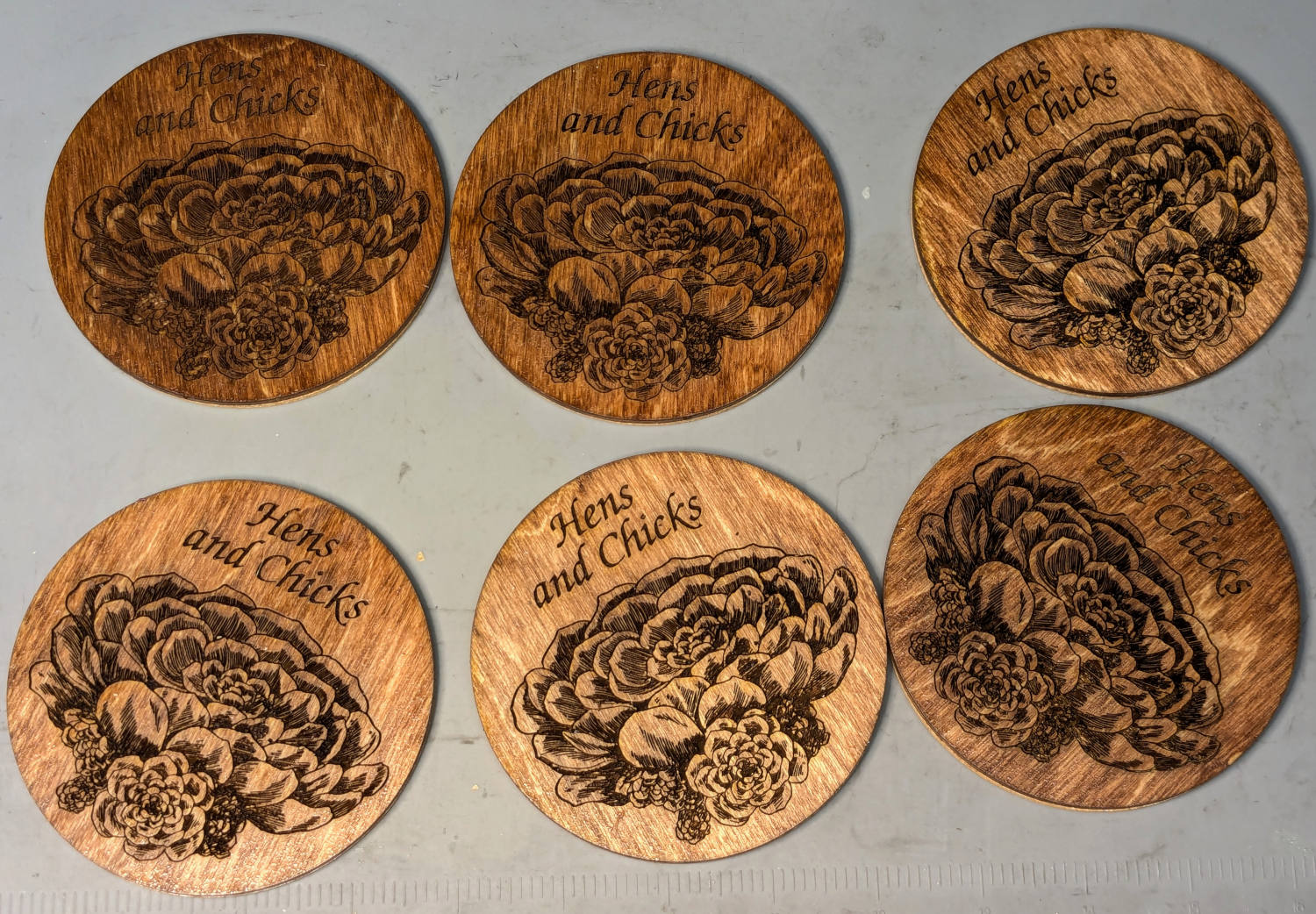
Mary’s Hens and Chicks gardening group is having a White Elephant gift swap, where one can get rid of anything vaguely garden-related without repercussions, so I ran off a set of eponymous coasters for practice:
Hens and Chicks Coasters – overview
They’re 3 mm laser plywood with English Chestnut stain and satin polyurethane sealant, with PSA cork on the underside. Even if (IMO) the stain came out too dark on some of them, they’re perfectly suited for the occasion.
It’s ordinary laser-grade 3 mm plywood with another wood inlay, sanded flat and covered with polyurethane sealer.
The key attraction: not fiddling with tiny veneer bits.
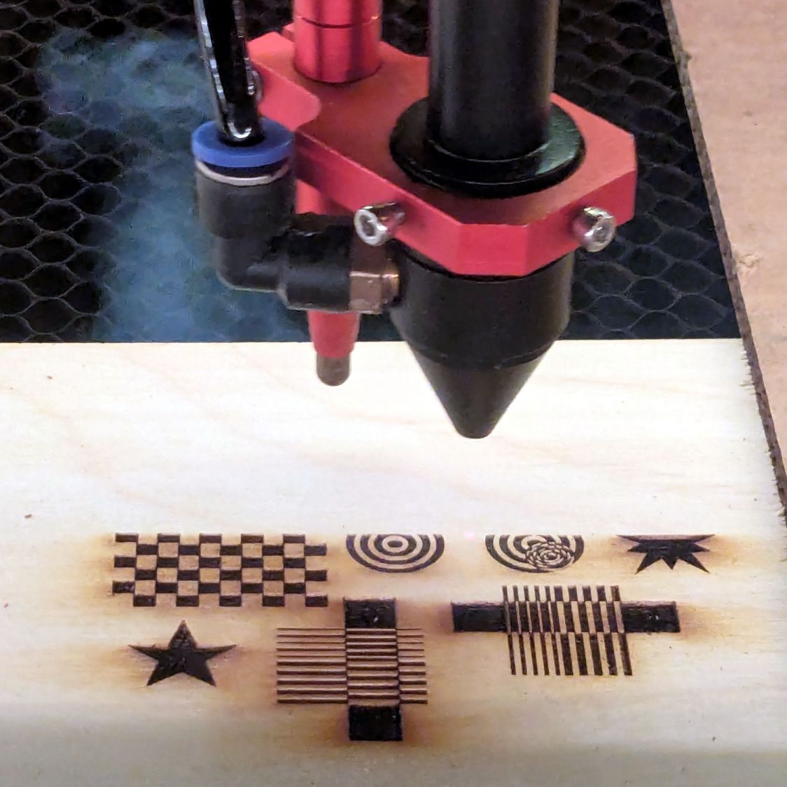
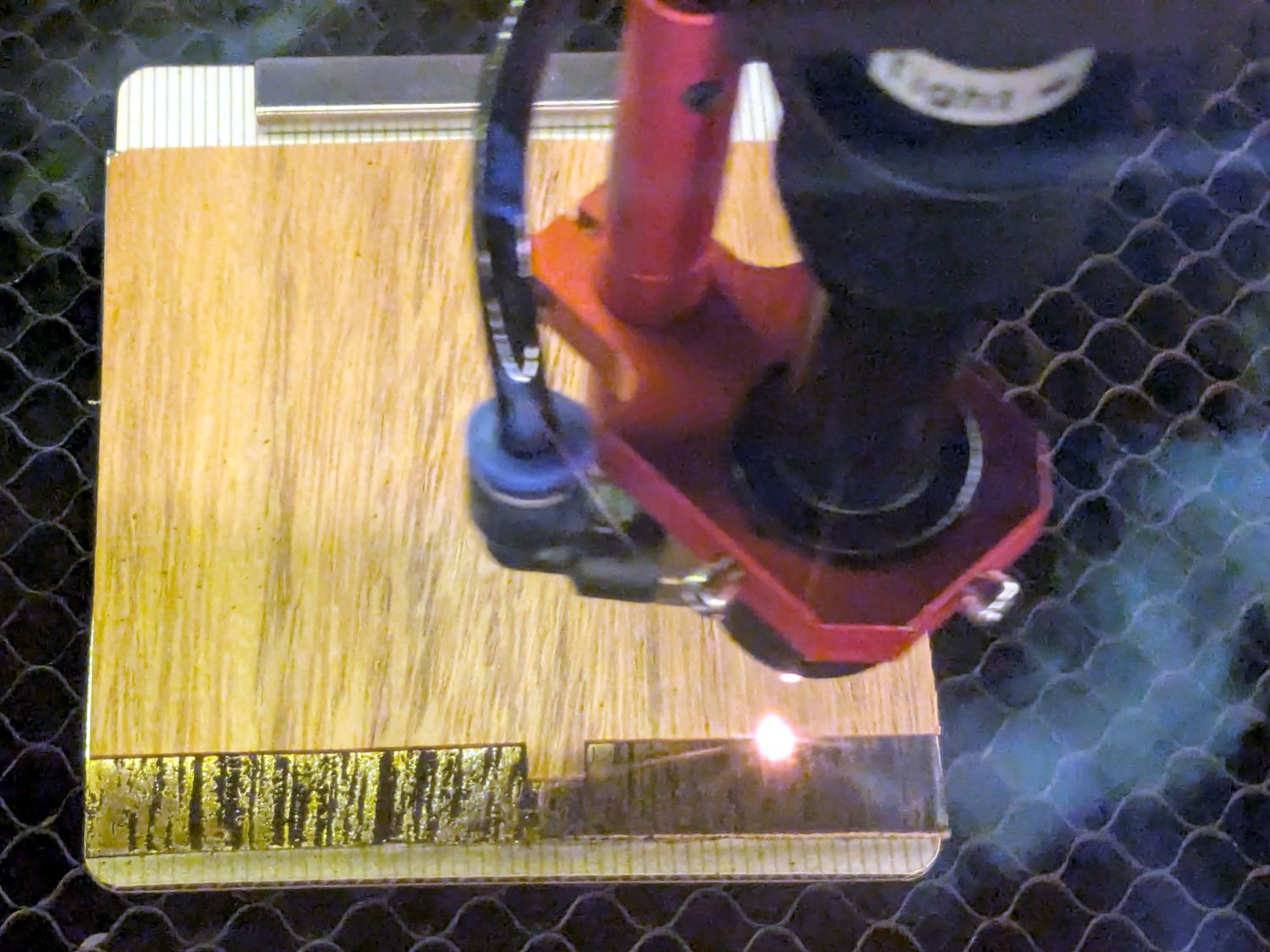
Cut the recesses in one pass with enough energy to make them at least as deep as the veneer thickness:
Marquetry test – plywood cutting
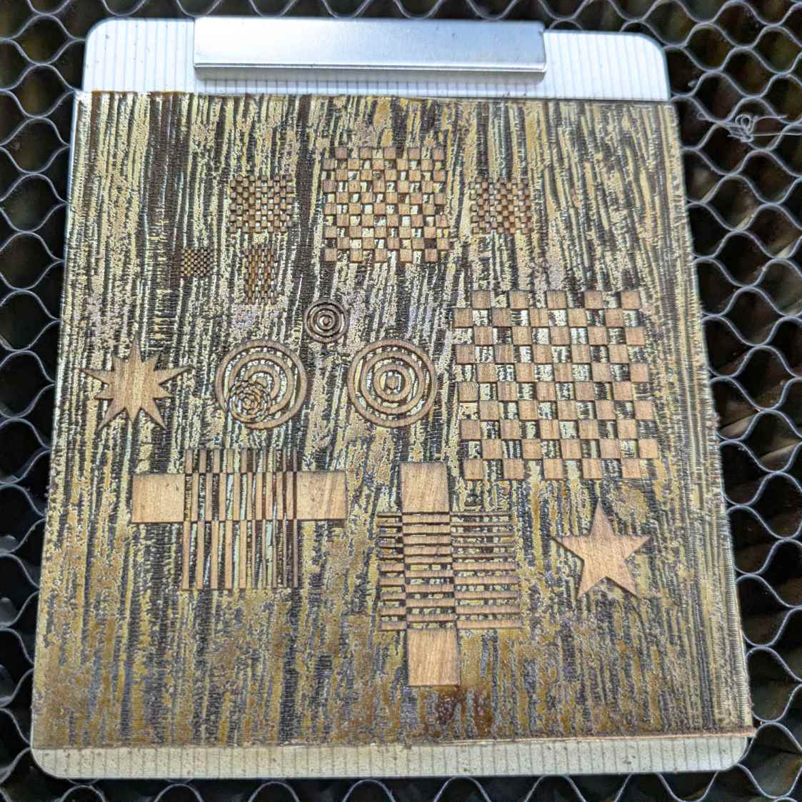
Press the veneer onto aluminum tape, taking care to avoid wrinkles and folds, and cut away everything that doesn’t go into those recesses:
Marquetry test – veneer cutting
Which looks gnarly when you’re done:
Marquetry test – veneer on tape
I cut the aluminum tape to fit within the corner targets around the plywood layout, thus simplifyingmaking possible aligning the positive veneer shapes with the negative plywood shapes while being unable to see either of them.
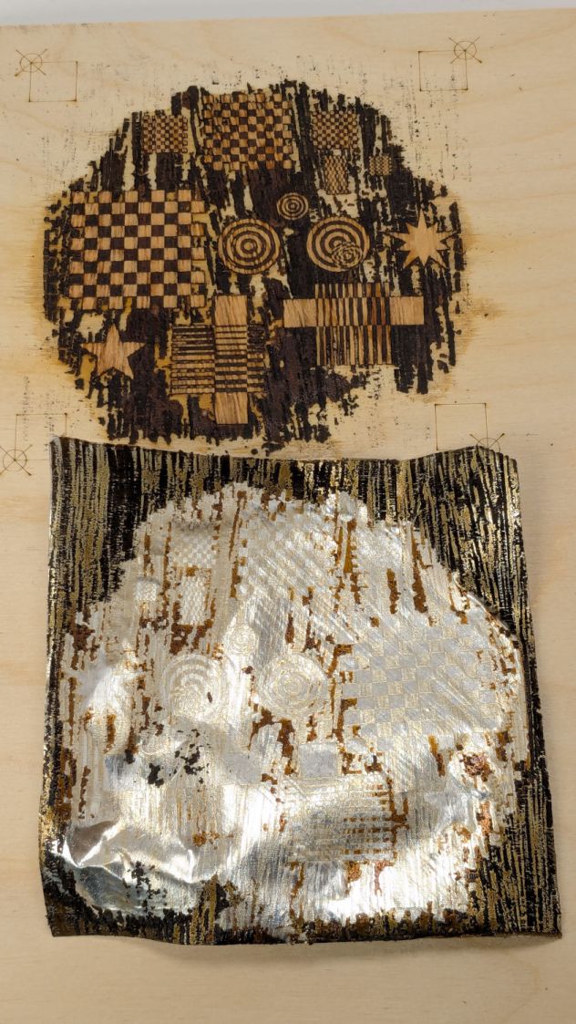
Slather wood glue over the plywood, make sure even the tiniest recesses are filled, align the aluminum, clamp the two firmly together, wait for a few days while the glue cures in that airless space, then peel off the aluminum:
Marquetry test – peeled
Which looked so awful I thought that was a disaster, not least because the veneer stood proud of the plywood, so it remained on the back of the bench for far too long.
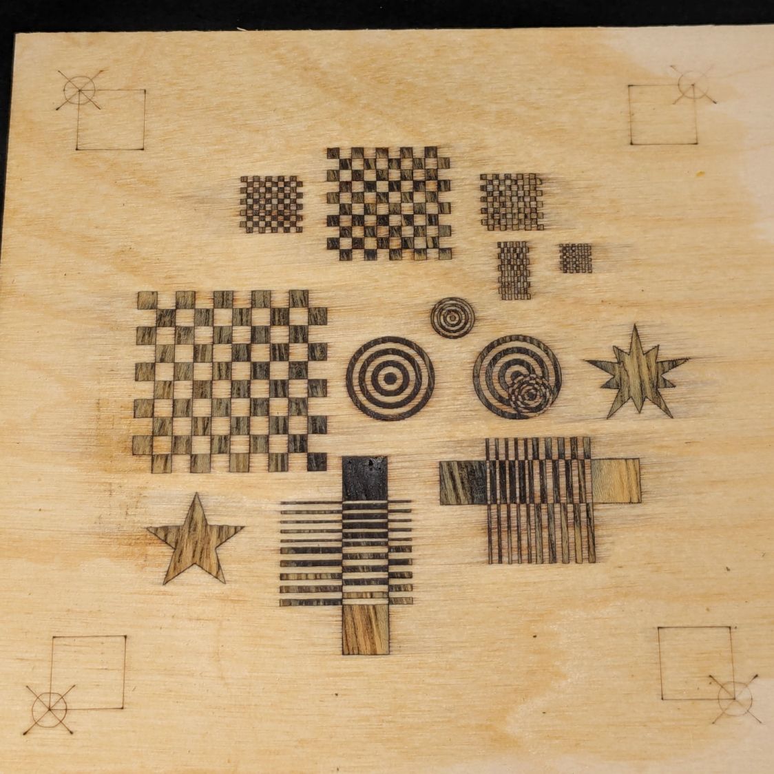
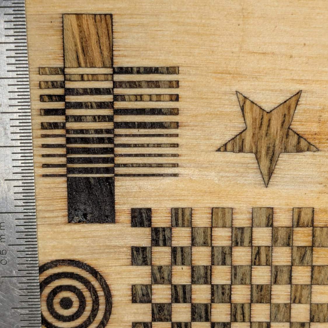
Eventually, having deployed the sander for another project, I sanded the veneer flush with the plywood to reveal the nearly perfect results in the lead picture. There’s a bit of smoke stain left in the grain, but the tiniest recesses have at least some veneer fill and the surface is entirely smooth.
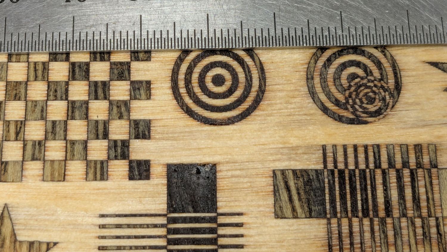
The overlaid circles worked out:
Marquetry test – detail 1
The darkest block and the smaller lines are badly smoke-stained veneer, as they have wood grain visible under magnification. I think those may not have fully entered their recesses and we’re seeing a very thin veneer layer soaked with soot-filled wood glue.
Another view:
Marquetry test – detail 2
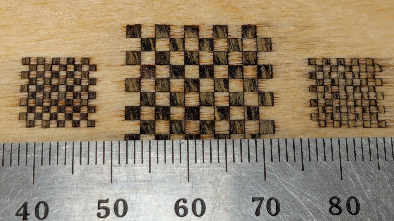
The checkerboard squares worked well;
Marquetry test – squares 1
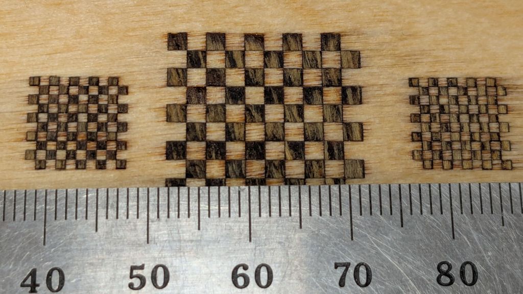
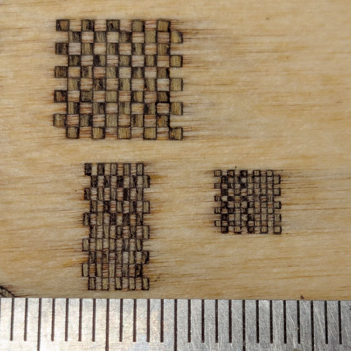
To my astonishment, even the 0.5 mm squares have some veneer inside, as do the 0.5×1.0 mm rectangles on the left:
Marquetry test – squares 2
Not knowing any better, there’s no kerf offset on any of the figures and they’re separated by about the 0.2 mm width of the focused spot.
Aligning the veneer to the recesses was tricky and I was not at all sure it had happened. I think larger shapes would be much easier and might give off a confirming squish as they meet their sockets.
Gotta try that again without the benefit of beginner’s luck.
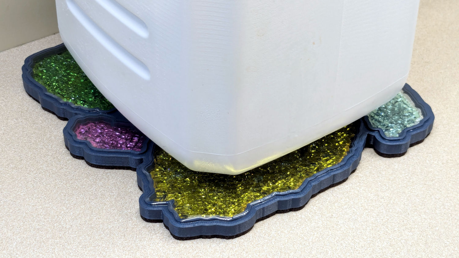
Those of long memory will recall our vermiculture setup in the basement that turns kitchen scraps into plant food. We accumulate scraps in plastic milk jugs, which jugs get recycled after they become grody.
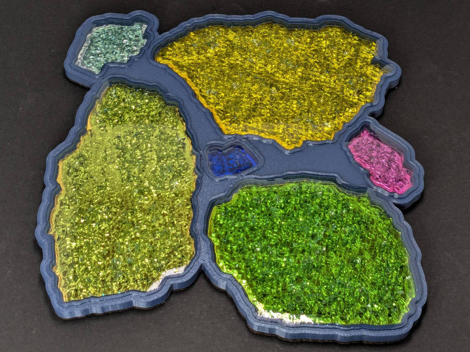
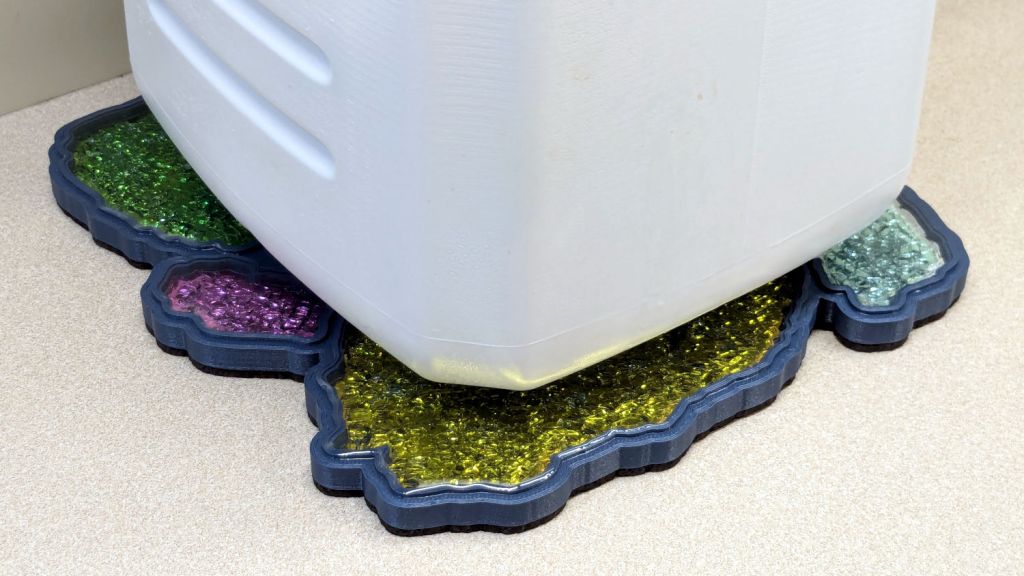
I finally made a decorative coaster to keep the sometimes-wet jug off the counter:
Printed Fragment Coaster 165mm – in use
This used several of the larger smashed glass fragments from the collection:
Fragments 165mm square – scan sample
They all fit inside a 165 mm square, with the conformal perimeter disguising the outline:
Run a bead of epoxy around the edge of each recess
Fill in the center with a thin layer
Squish the metallized paper reflector in place starting from one end to ease the bubbles out
Cover the reflector with another layer of epoxy
Lay the glass fragment down starting at one end
Press gently down to get all the bubbles out
Cover the glass with more epoxy
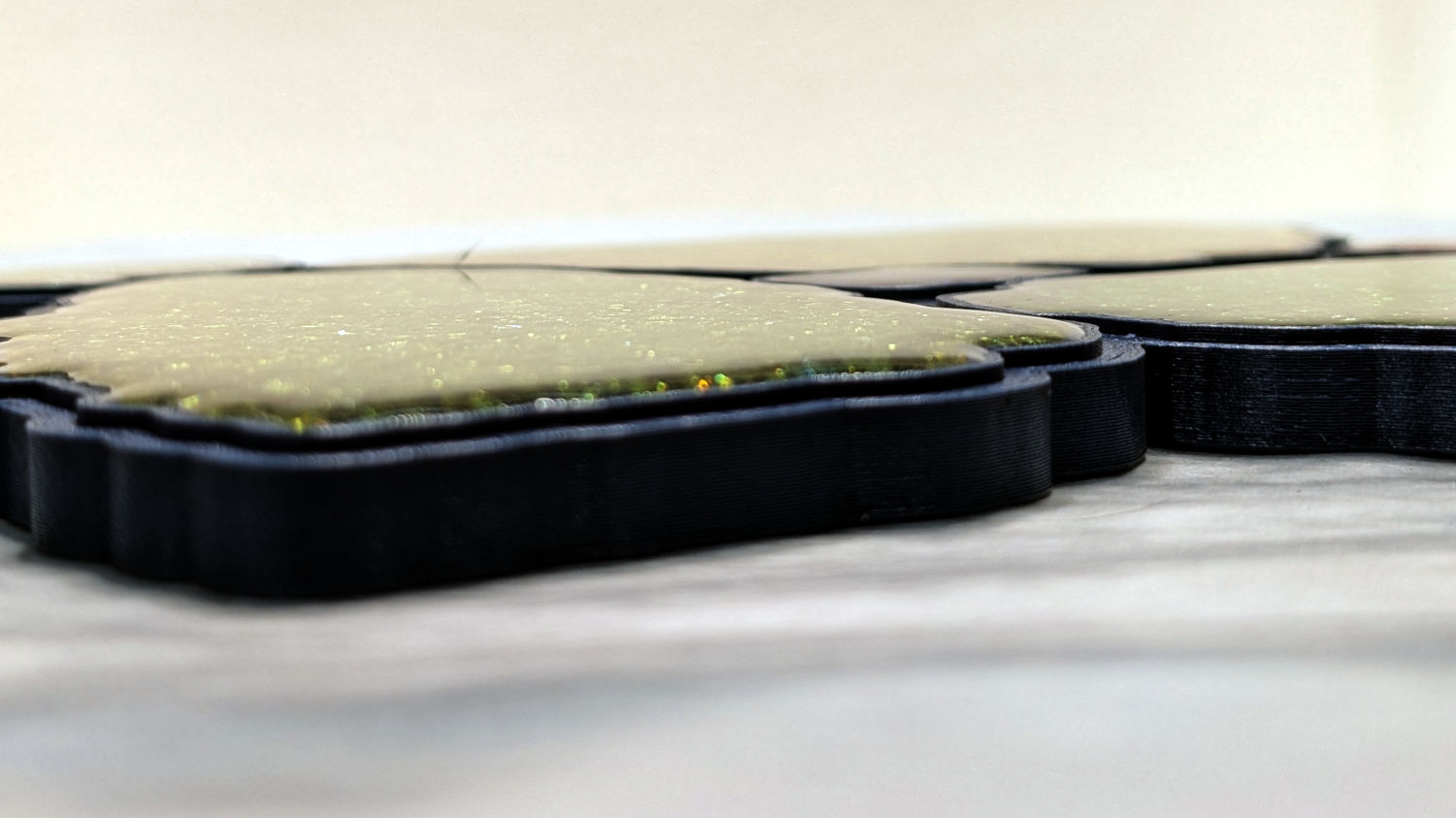
I dripped enough epoxy on each fragment to form a meniscus without having it go over the rim:
Printed Fragment Coaster 165mm – epoxy meniscus
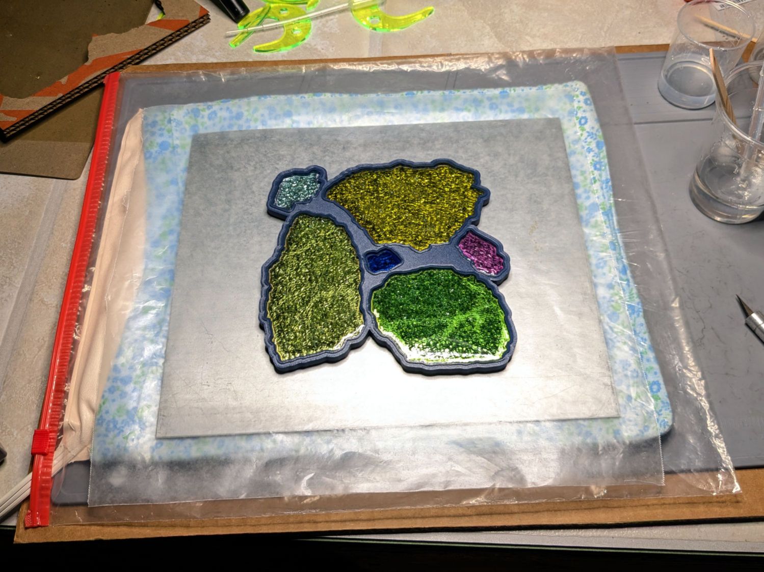
The Basement Shop temperature is just over 60 °F, so I put a heating pad in a huge ziplock bag, laid an aluminum sheet atop it as a heat spreader, put some waxed paper on the aluminum just in case, then did the filling described above:
Printed Fragment Coaster 165mm – warming setup
A cardboard box on top helped the heating pad keep the coaster at a uniform 85 °F, slightly warmer than the epoxy instructions recommend, but it cured overnight with a wonderfully shiny surface.