
The motivation for making Yet Another Coaster was to see if combining a few techniques I’ve recently learned would produce a nicer result.
Spoiler: Yup, with more to be learned and practiced.
This is a somewhat nonlinear narrative reminding me of things to do and not do in the future, so don’t treat it as a direct how-to set of instructions.
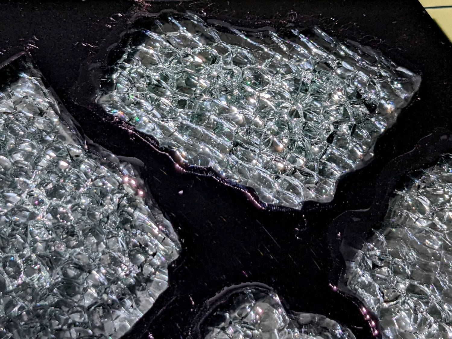
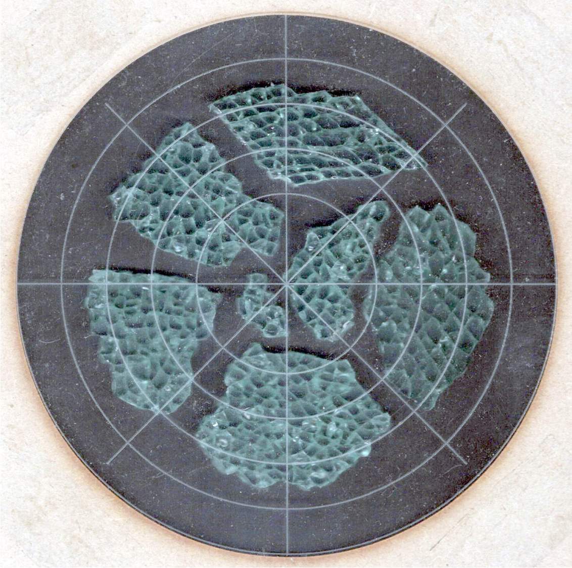
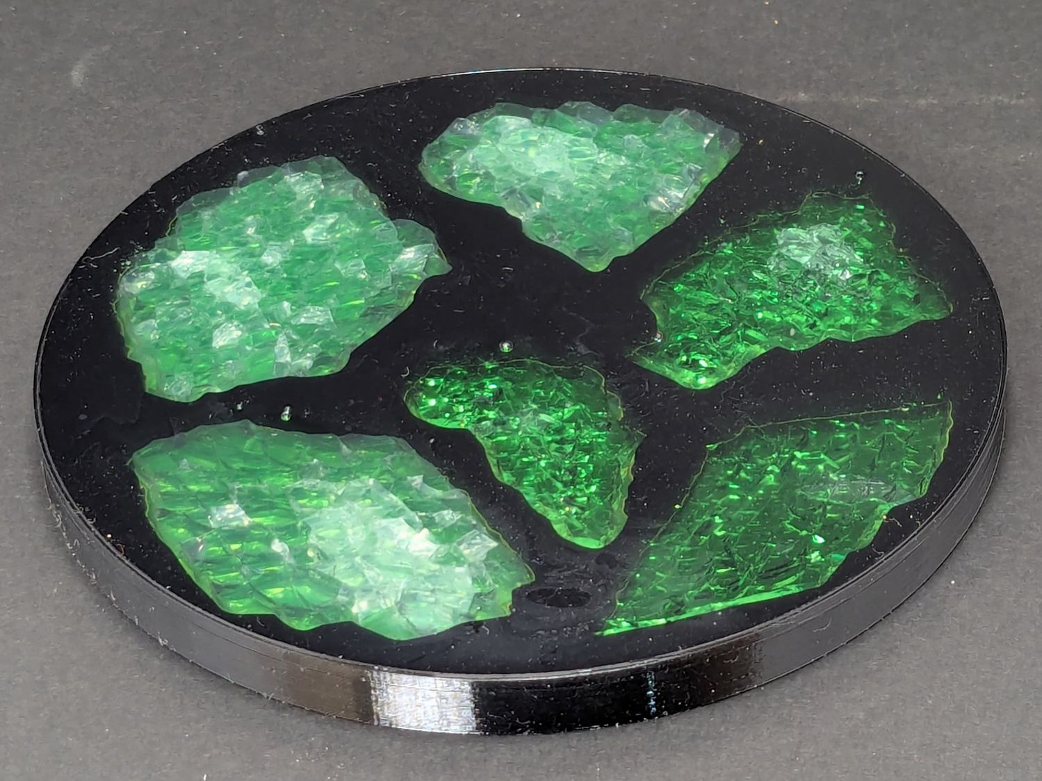
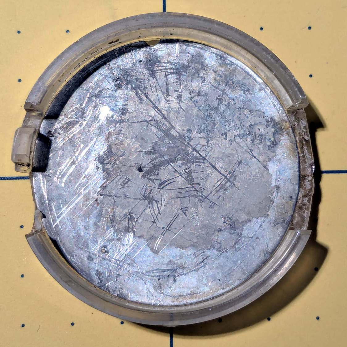
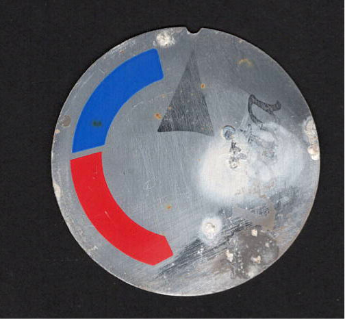
Thus far, the best way to highlight fragments of smashed glass has been to put them atop an acrylic mirror:
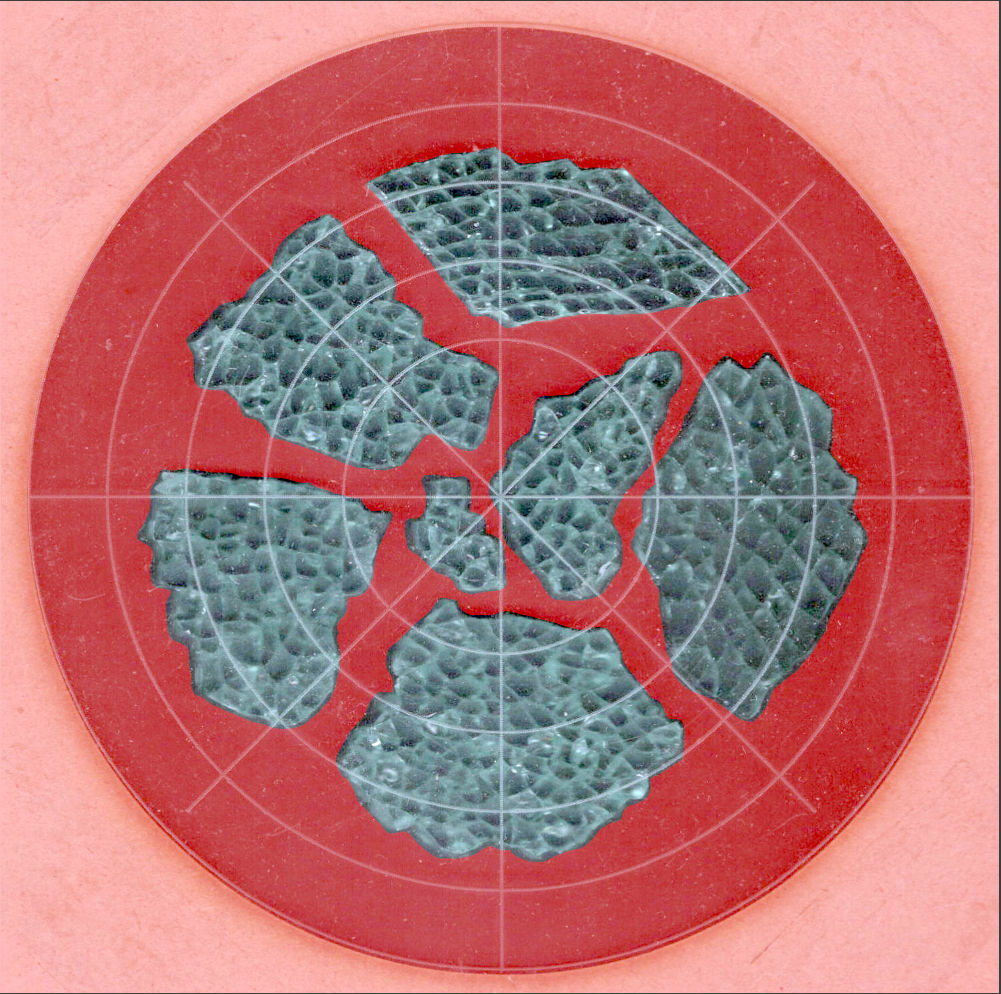
But a 3 mm acrylic mirror layer makes for a rather thick coaster:
The glass fragments sit inside holes in the next two (or three or whatever) acrylic layers, which must have a total thicknesses slightly more than the glass thickness and remain properly aligned while assembling the whole stack:
Bonus: all that cutting generates an absurd amount of acrylic scrap. I eventually put much of it to good use, but not producing it in the first place would be a Good Thing …
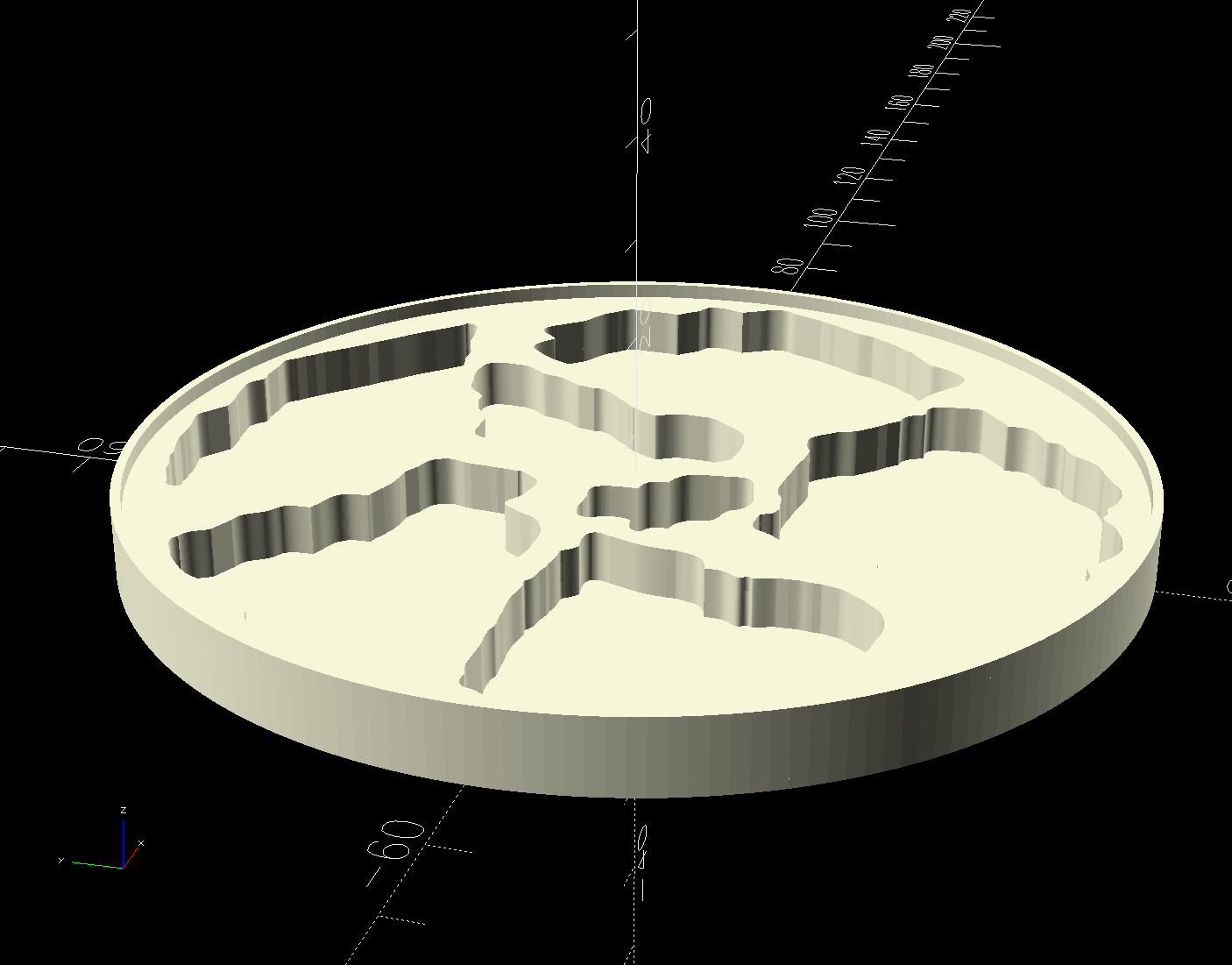
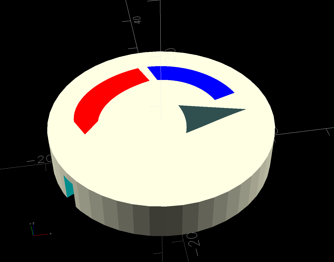
So 3D print the entire base, which requires generating a solid model with recesses for the fragments:
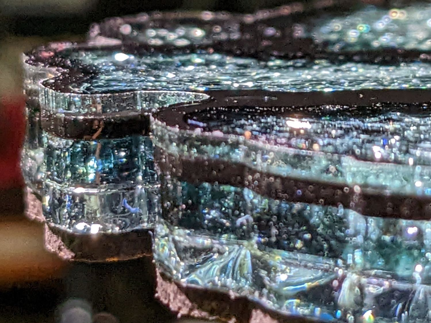
Because there’s no real justification for an optical-quality mirror under smashed glass, use reflective metallized paper in the recesses as reflectors:
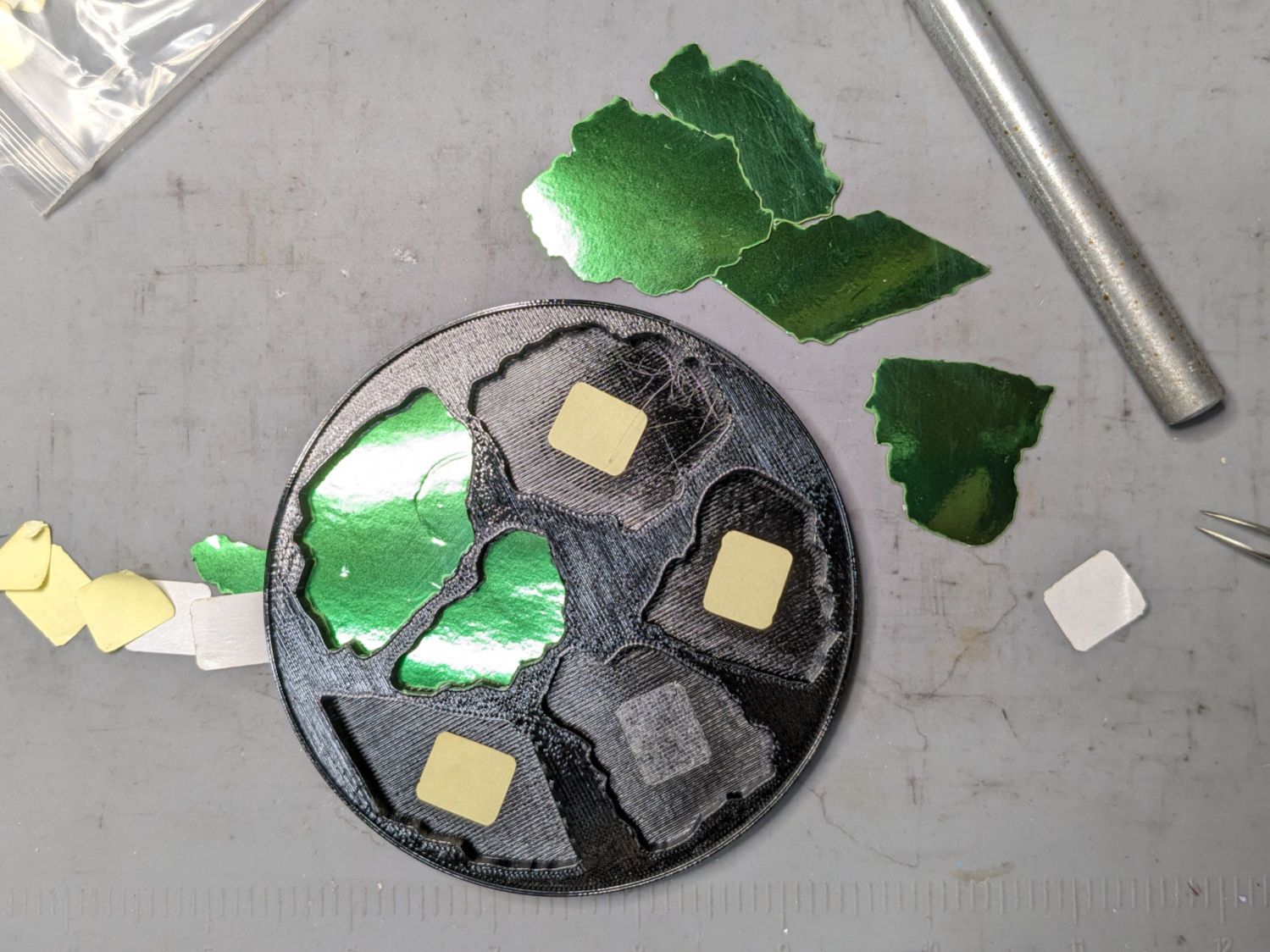
The glass is more-or-less greenish-blueish, so I used a strip of green metallized paper that made the glass fragments green. Obviously there’s some room for choice down there.
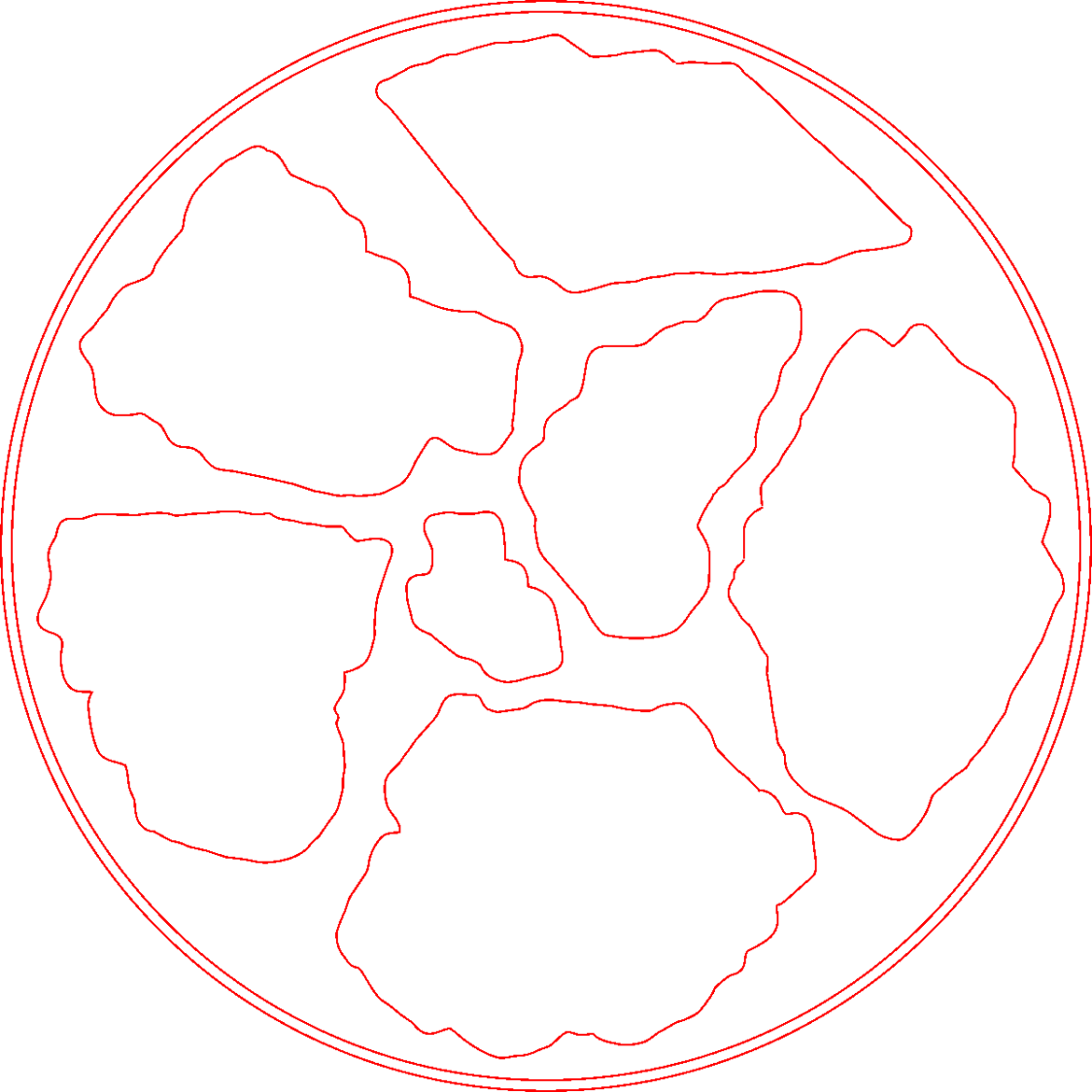
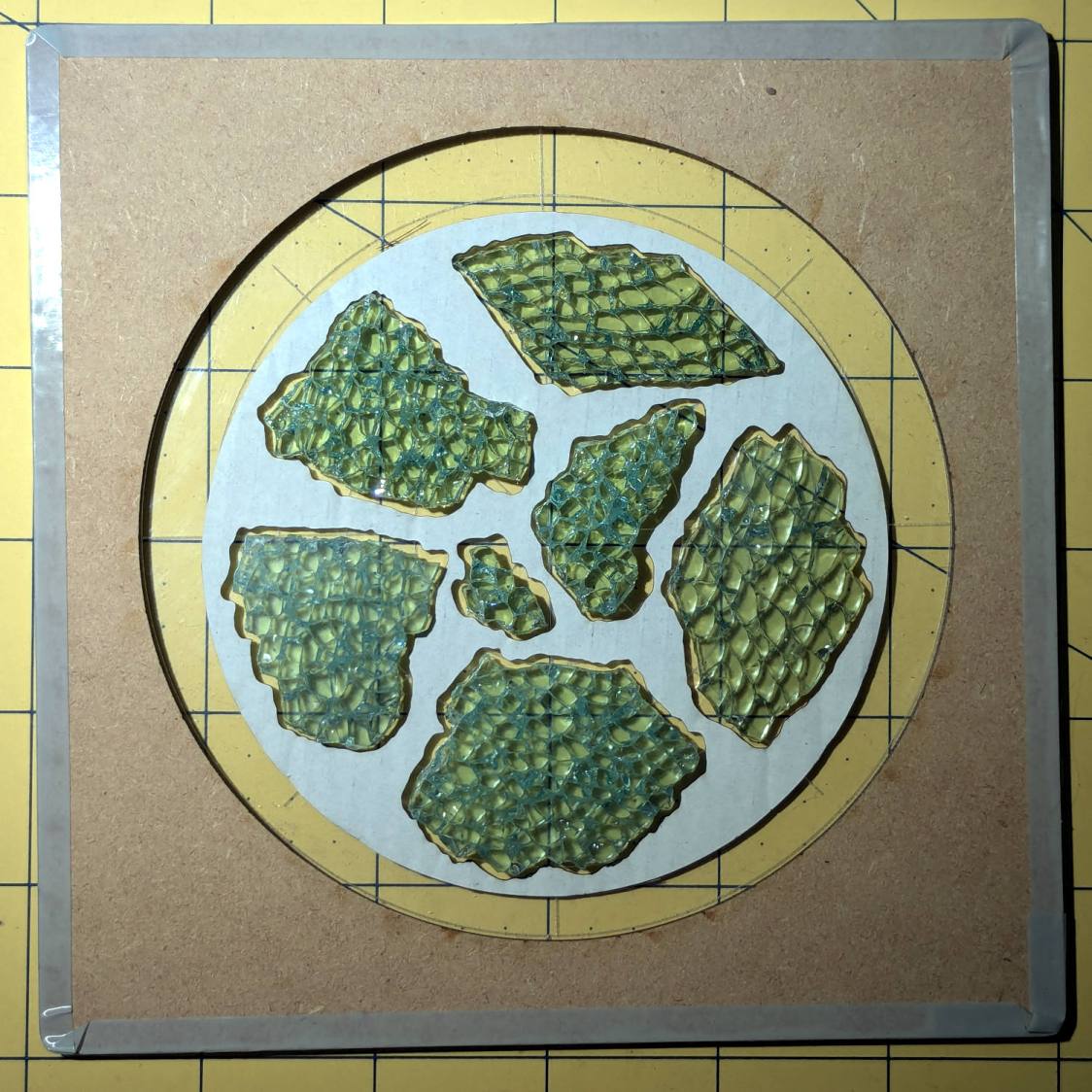
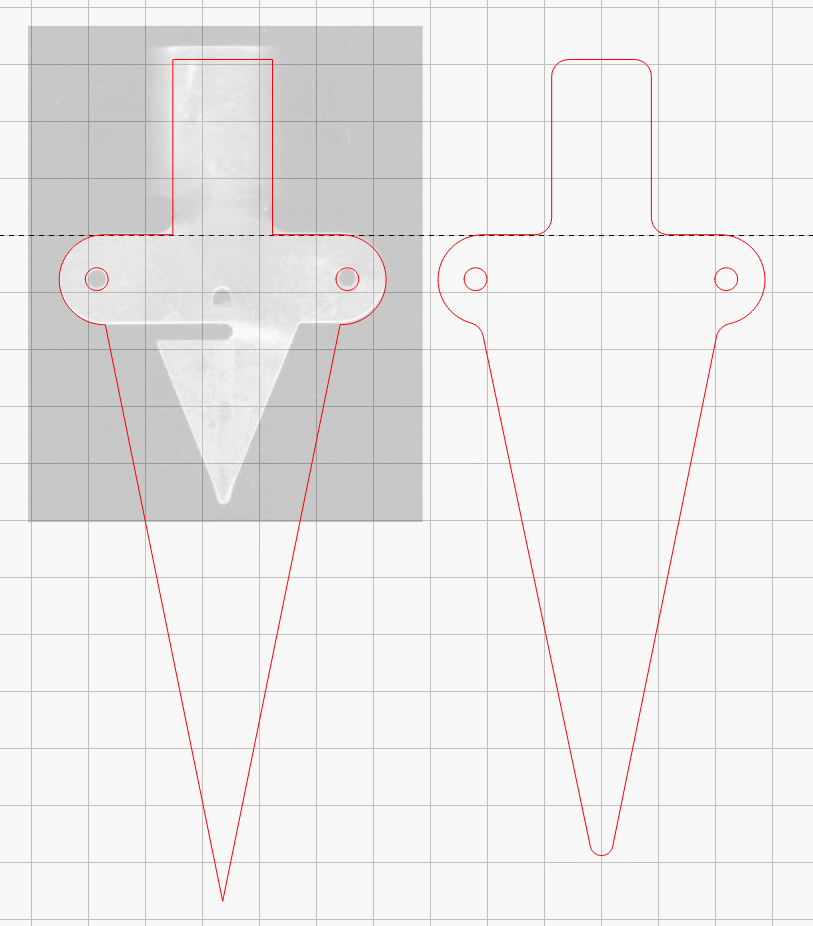
Both the base and the reflectors use outlines of the fragments, so I started with a scan of the approximate layout in GIMP:
I traced the outline of each fragment using the Scissors Select Tool, which lays line segments along the sharpest gradient between clicked points, then switched into Quick Mask mode to adjust & smooth the results:
That’s the result after sketching & saving all the paths as separate SVG files to allow importing them individually into InkScape, OpenSCAD, and LightBurn.
Which turned out to be suboptimal, as it let me write an off-by-one blooper omitting the last file from the OpenSCAD model:
fn = "Fragment layout - 4in.svg";
fp = ["A","B","C","D","E","F"];
<snippage>
        for (p = fp)
          import(fn,id=str("Fragment ",p));
A better choice puts all the paths into a single named group, saved as a single SVG file, then importing that group from the file using its name, along these lines:
fn = "Fragment layout - 4in.svg";
fg = ["Fragments"];
<snippage>
        import(fn,id=fg);
It’s not clear if I can do that directly from GIMP by saving all the paths in a single file, then importing that lump into Inkscape as a group, but it’ll go something like that.
After getting the fragment paths into Inkscape, add a 0.5 mm offset to each path to clear any non-vertical edges. This will be checked with the template cut using LightBurn as described below.
Add a 1 mm rim around the outside, with the 4 inch OD matching the usual PSA cork base:
Now’s the time to nudge / rotate the outlines so they have at least a millimeter of clearance on all sides / ends, because that’s about as thin a section of printed plastic as you want.
Locating the center of the OD (and, thus, everything inside) at the lower-left corner of the Inkscape page will put them at the OpenSCAD origin. I have set Inkscape to have its origin at the lower left, rather than the default upper left, so your origin may vary.
Select one of the paths:
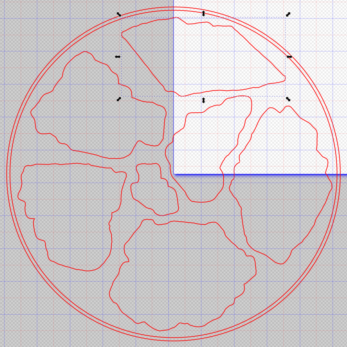
Then set the ID in its Object Properties:
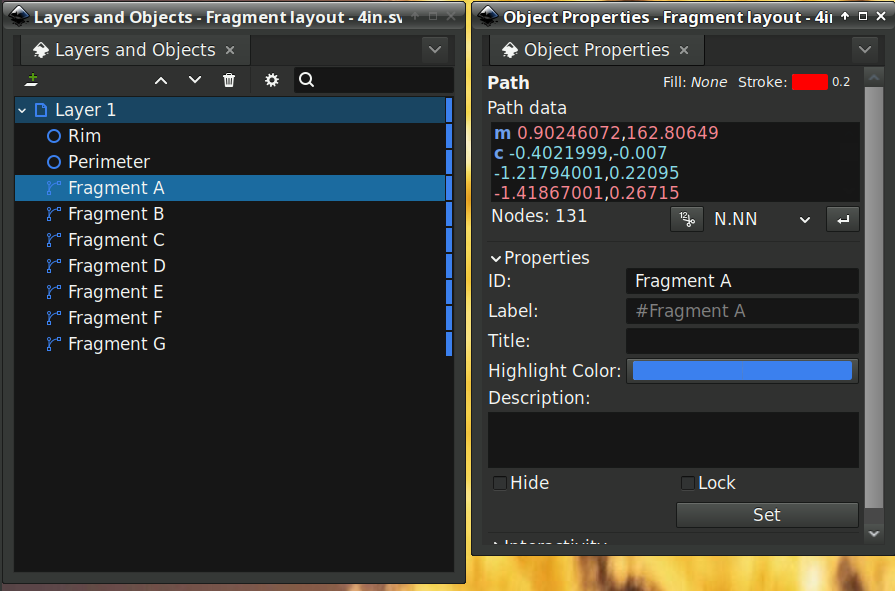
There is an interaction between the name over in the Layers and Objects window, which apparently comes from the GIMP path name for the imported fragments, and the resulting ID and Label in the Object Properties window. However, renaming an object on the left, as for the Rim and Perimeter circles, does not set their ID or Label on the right. Obviously, I have more learning to do before this goes smoothly.
With everything laid out and named and saved in an SVG file, the OpenSCAD program is straightforward (and now imports all the fragments):
include <BOSL2/std.scad>

NumSides = 4*4*3*4;

fn = "Fragment layout - 4in.svg";
fp = ["A","B","C","D","E","F","G"];

FragmentThick = 5.0;

BaseThick = 1.0;
RimHeight = 1.5;

union() {
  linear_extrude(h=BaseThick)
    import(fn,id="Perimeter",$fn=NumSides);
  linear_extrude(h=BaseThick + FragmentThick + RimHeight)
    difference() {
      import(fn,id="Perimeter",$fn=NumSides);
      import(fn,id="Rim",$fn=NumSides);
  }
  up(BaseThick - 0.05)
    linear_extrude(h=FragmentThick)
      difference() {
        import(fn,id="Perimeter",$fn=NumSides);
        for (p = fp)
          import(fn,id=str("Fragment ",p));
      }
}
Which squirts out the solid model appearing above.
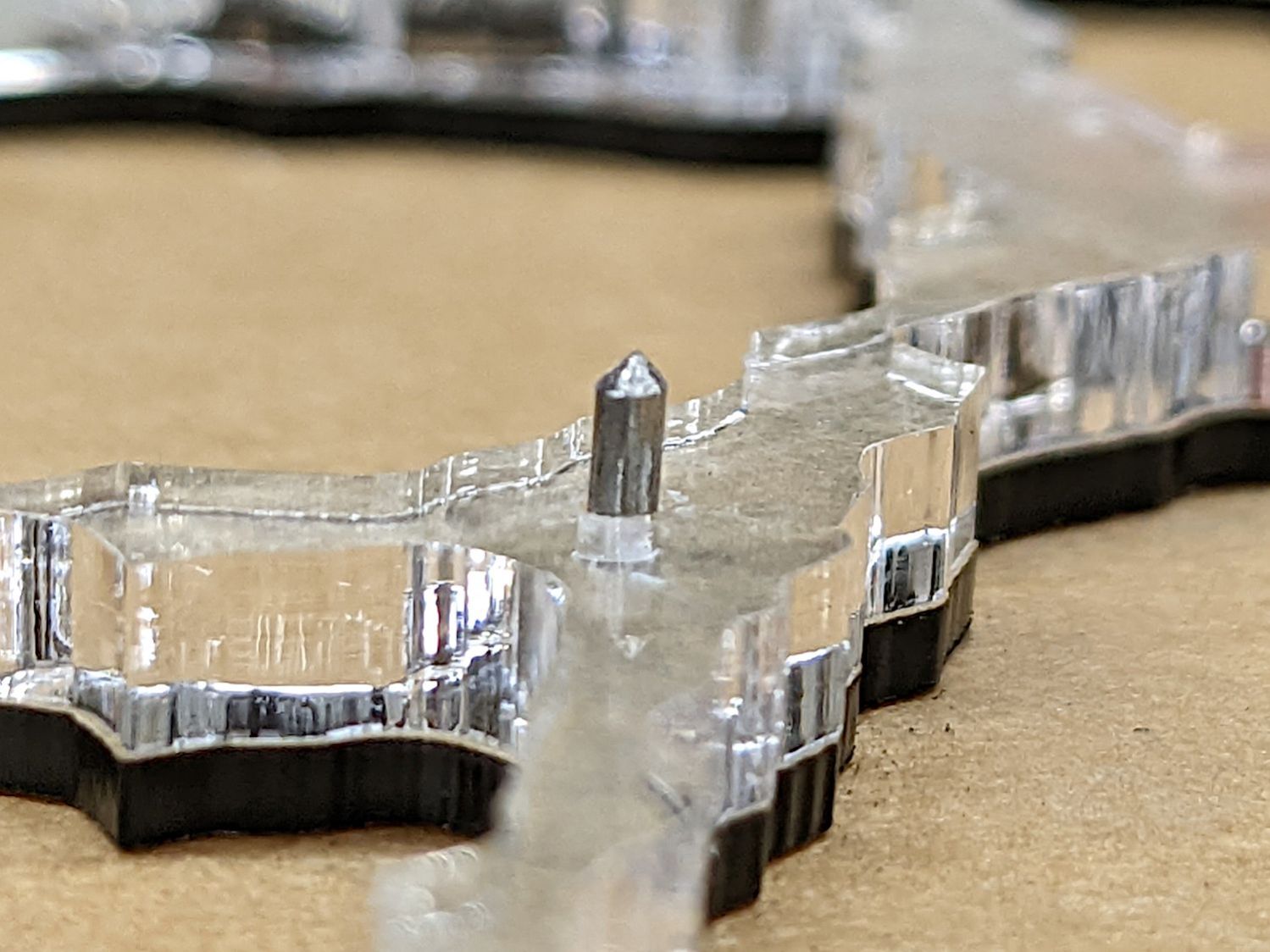
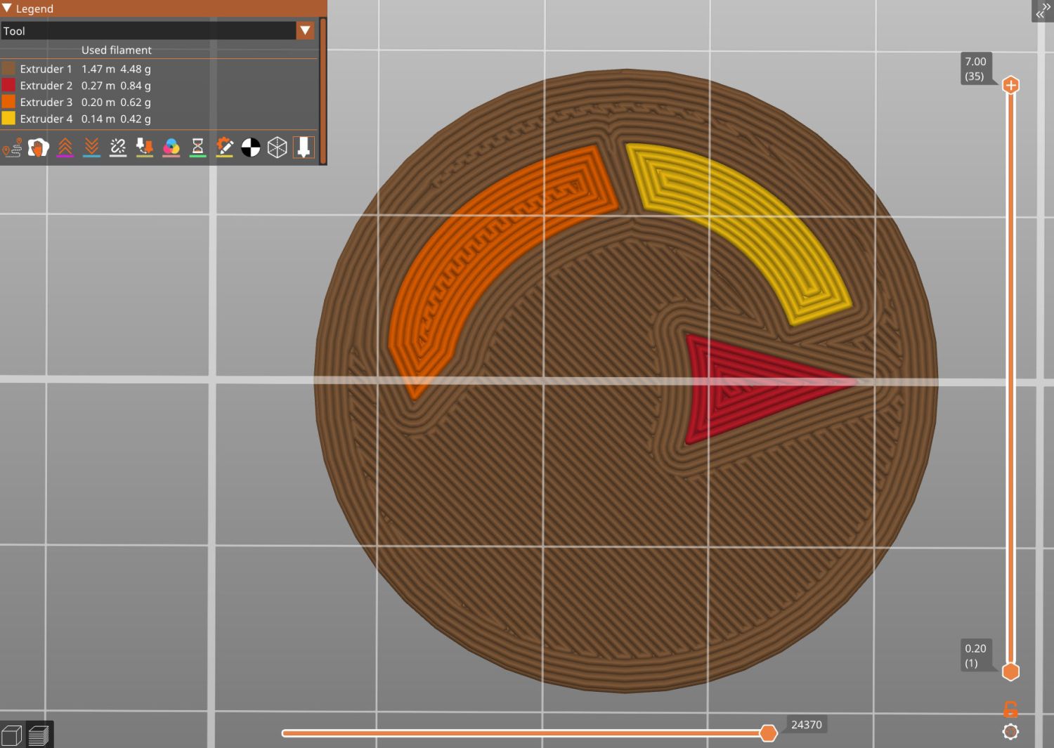
Feeding it into PrusaSlicer turns the model into something printable:
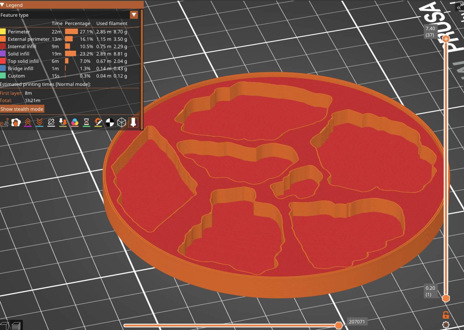
And after supper I had one in my hands.
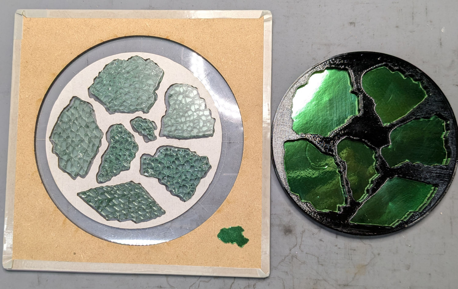
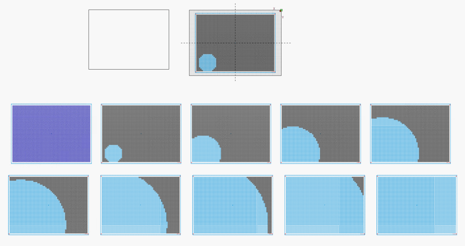
Before doing that, however, import the same SVG file into LightBurn, as on the left:
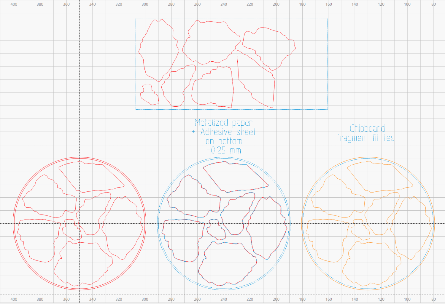
On the right, duplicate it, put the inner Rim on a tool layer, put the rest on a layer set to cut chipboard, and make a template to verify those holes fit around the fragments:
Which a few didn’t, explaining why I go to all that trouble. Iterate through GIMP → paths → SVG → Inkscape → LightBurn until it’s all good. Obviously, you do this before you get too far into OpenSCAD, but they all derive from the Inkscape layout, so there’s not a lot of wasted motion.
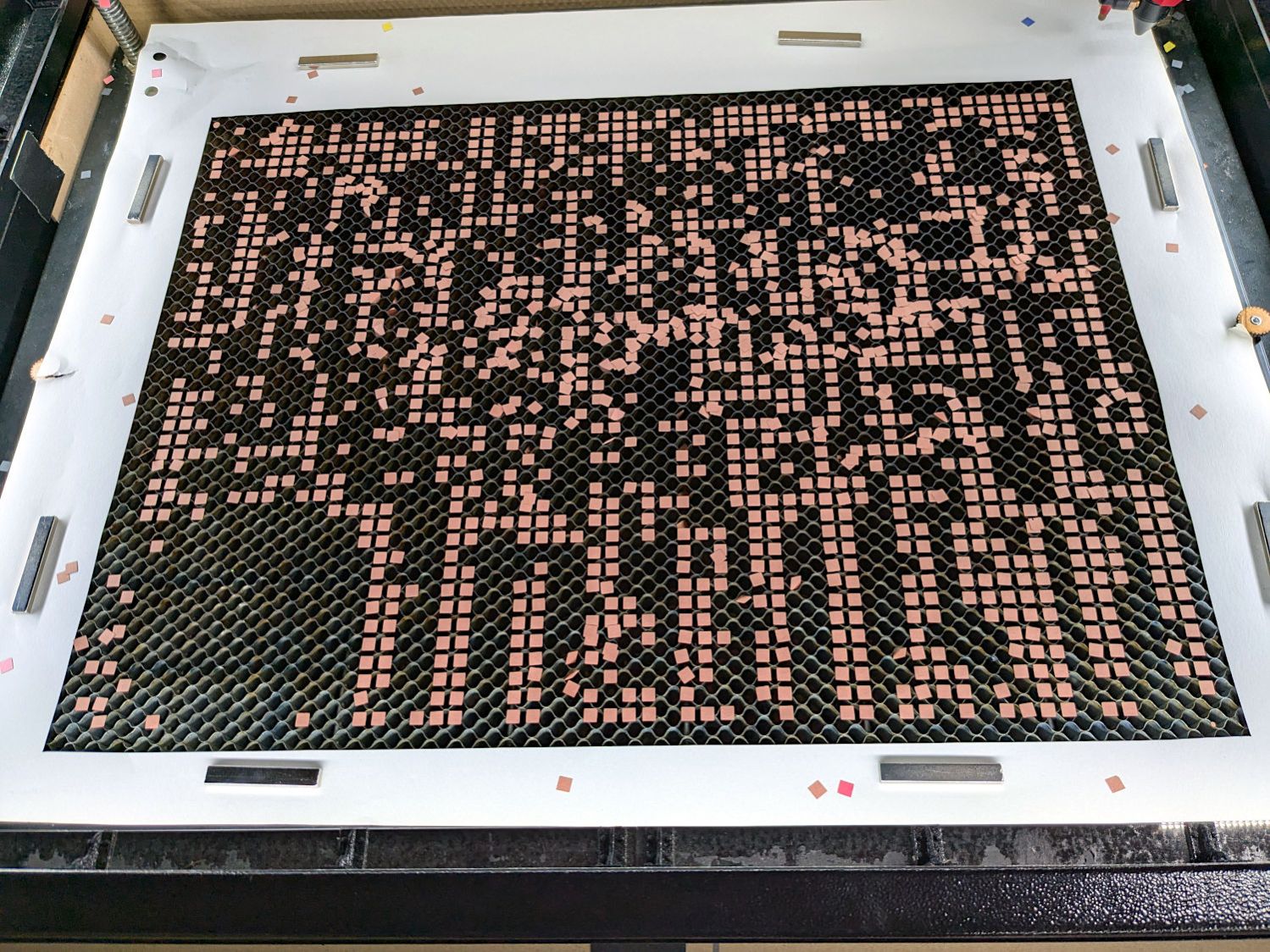
The middle LightBurn layout insets the fragment outlines by 0.25 mm to ensure the paper fits easily and puts them on a layer set to cut metallized paper. Those fragments then get duplicated and rearranged within the rectangle on the top to fit a strip of metallized paper from the scrap box. Fire The Laser to cut them out and stick them to the bottom of their corresponding 3D printed recesses with leftover snippets of craft adhesive sheet as shown above.
I had originally intended to cover the bottom of the entire sheet of metallized paper with an adhesive sheet, but realized the whole affair was going to be submerged in epoxy, so just making sure the paper didn’t float away would suffice.
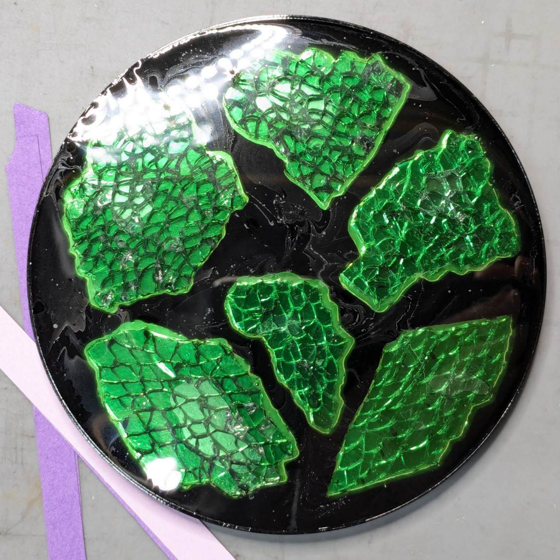
Next, mix up some epoxy …


