Ed Nisley's Blog: Shop notes, electronics, firmware, machinery, 3D printing, laser cuttery, and curiosities. Contents: 100% human thinking, 0% AI slop.
The bushes & trees along the Dutchess Rail Trail were reaching out to touch us again, so I took some slow rides with many stops.
Maple Oak trees along Page Park Drive:
DCRT Brush Trimming – oak – 2025-07
Blackthorn encroaching through the fence at Overocker:
DCRT Brush Trimming – blackthorn – 2025-07
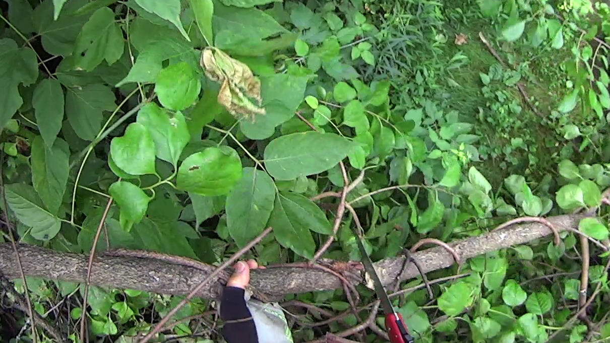
A tree somebody tossed down the trail bank near Morgan Lake:
DCRT Brush Trimming – discarded tree – 2025-07
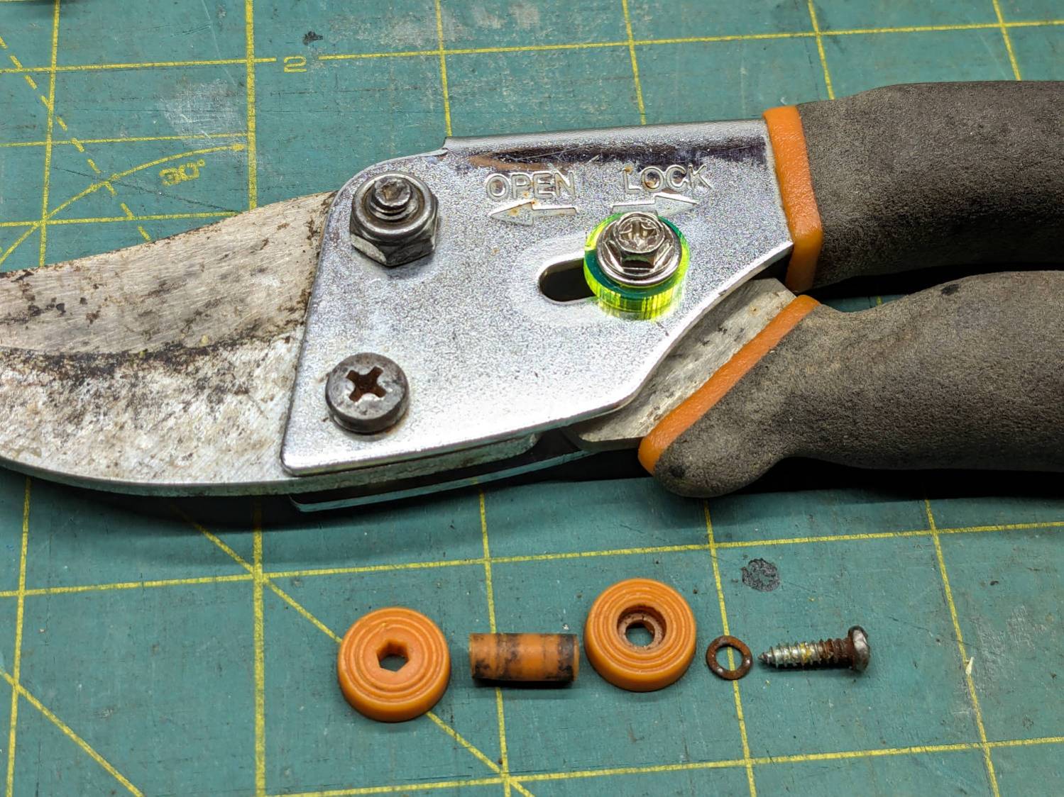
The slide lock on my trusty rehabilitated Fiskars bypass pruner worked loose and began sliding into the LOCK position when held overhead, then fell apart during disassembly:
Fiskars pruner – lock rebuild
The lock now consists of:
An M4 × 12 mm nut from a Chicago Screw that exactly matched the 5 mm OD cylinder passing through the pruner body
A laser-cut fluorescent acrylic disk for thumb grippiness
A washer just because
An M4 hex-head screw
A dab of Loctite bonding screw to nut
Clean the blades with alcohol and it’s ready for the rest of the season.
I should have put a wave washer in the stack for some springiness, but it works surprisingly well for what it is.
Now: discover how long acrylic lasts out there in the wild.
Update: Yeah, the lock needed a wave washer for more friction, which became apparent after the first overhead branch.
After fixing the X axis drive, the CNC-3018XL table moved properly again, so I measured its overall alignment:
3018CNC – table height measurement
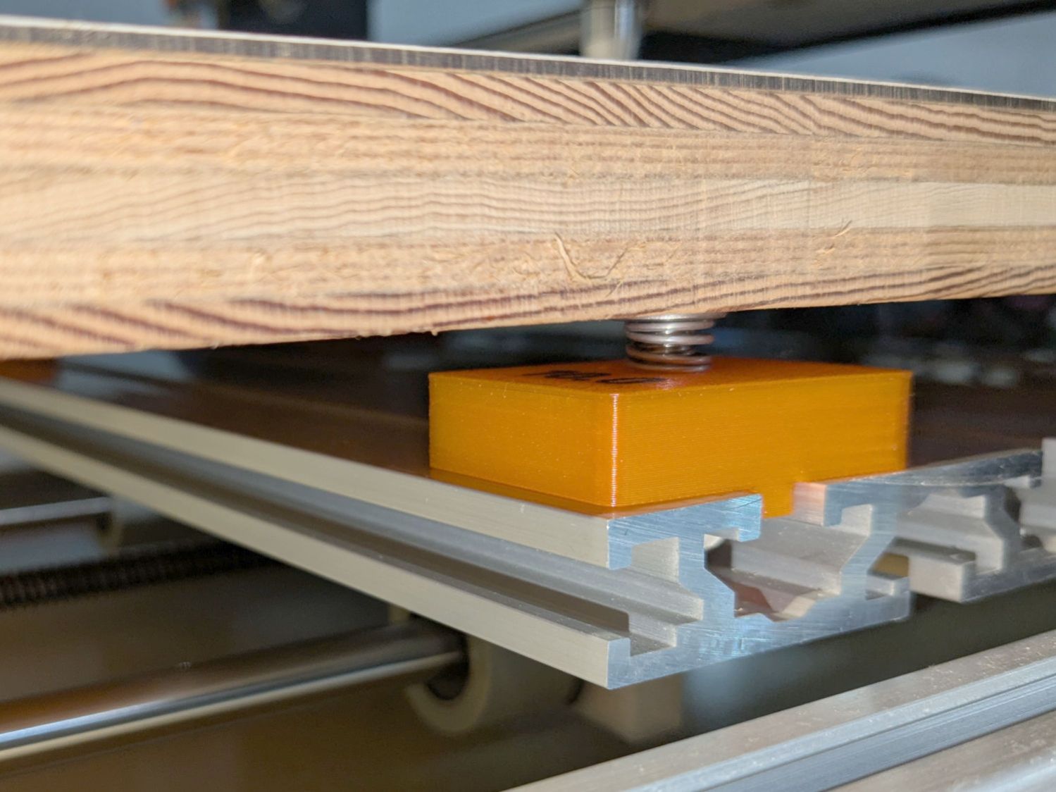
The +Y side (on the left in the photo, keeping in mind I’ve rotated the axes) turned out to be 0.7 mm too low, so I made a set of riser blocks to level the tabletop:
Table Riser – solid model
The 10 mm height would ram the tip of a Pilot pen about 10 mm below the tabletop surface, were it not for the spring-loaded pen holder:
Pilot V5RT holder – installed
The 0.7 mm difference in height levels the tabletop:
CNC3018XL – table riser positions
The OpenSCAD code produces an SVG outline I intended to use for a foam pad, but then I found a quartet of springs that worked even better:
CNC3018XL – table spring mount
So it’s now aligned within ±0.3-ish mm across the surface, with the unflatness of a slab cut from a 1955-era Formica kitchen countertop accounting for most of the difference in a swale from Quadrant III across the origin to Quadrant I.
Which a check plot using an old file shows will be Flat Enough for my simple needs:
CNC3018XL – test plot
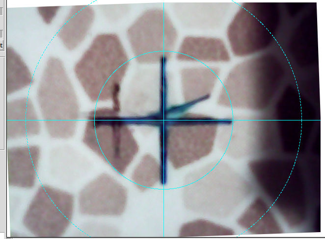
Having the camera alignment remain exactly spot on came as a pleasant surprise:
Camera Alignment check
The faded cross to the left came from the table’s previous position; there’s no positive index between the countertop slab and the underlying T-slots.
Part of the motivation for these blocks was to verify PrusaSlicer automagically handles filament / color changes between two objects, as long as OpenSCAD hasn’t unioned them as part of a common transformation. Not having to cut out the socket around the text simplifies the code from what I’d been doing with previous objects.
This file contains hidden or bidirectional Unicode text that may be interpreted or compiled differently than what appears below. To review, open the file in an editor that reveals hidden Unicode characters.
Learn more about bidirectional Unicode characters
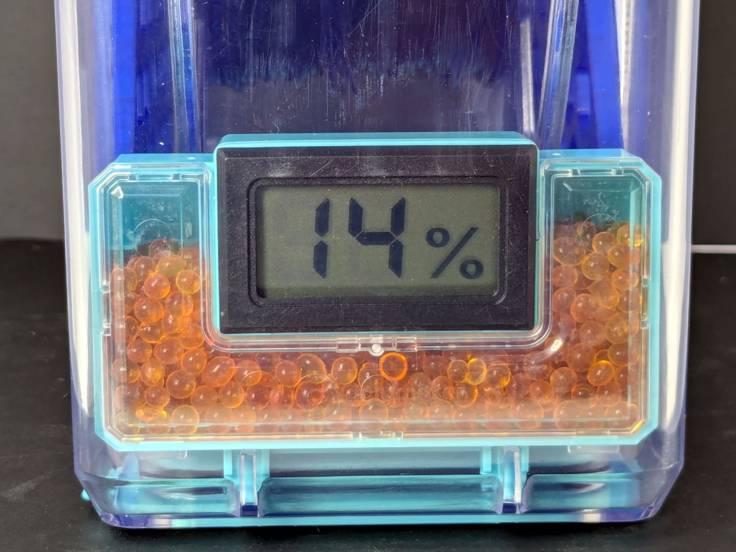
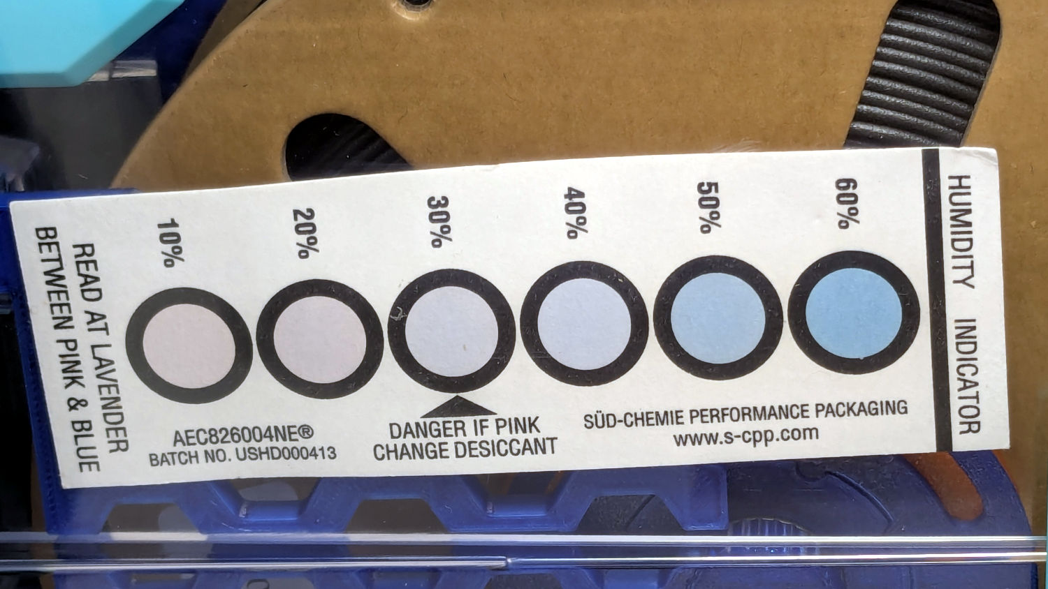
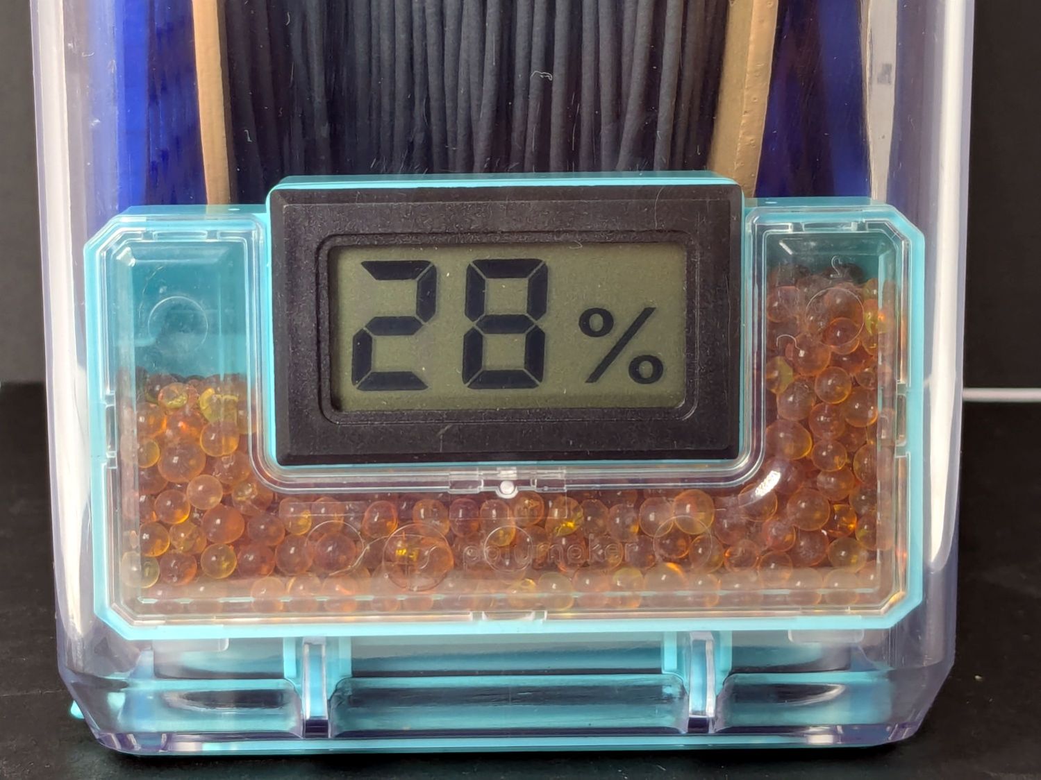
A week after installing 25 g of fresh silica gel, without any outside influence other than using some of the filaments to build things, I recorded the humidity meter reading, the indicator card colors, and the weight gain.
Click on any picture for more dots and to get rid of the captions and their stylin’ photo-blur.
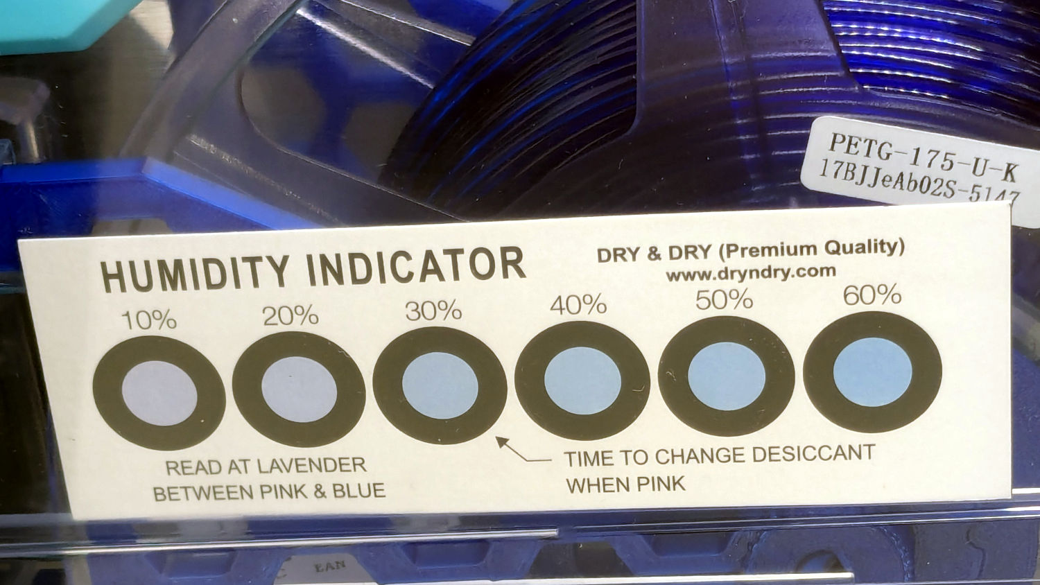
White PETG, gain 0.6 g:
Polydryer – 14 pctRH – meter – white PETGPolydryer – 14 pctRH – card – white PETG
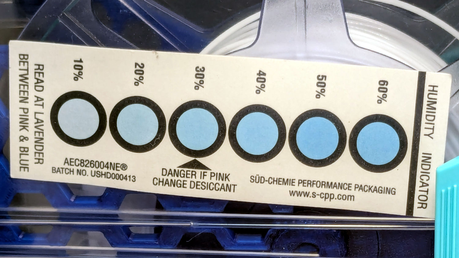
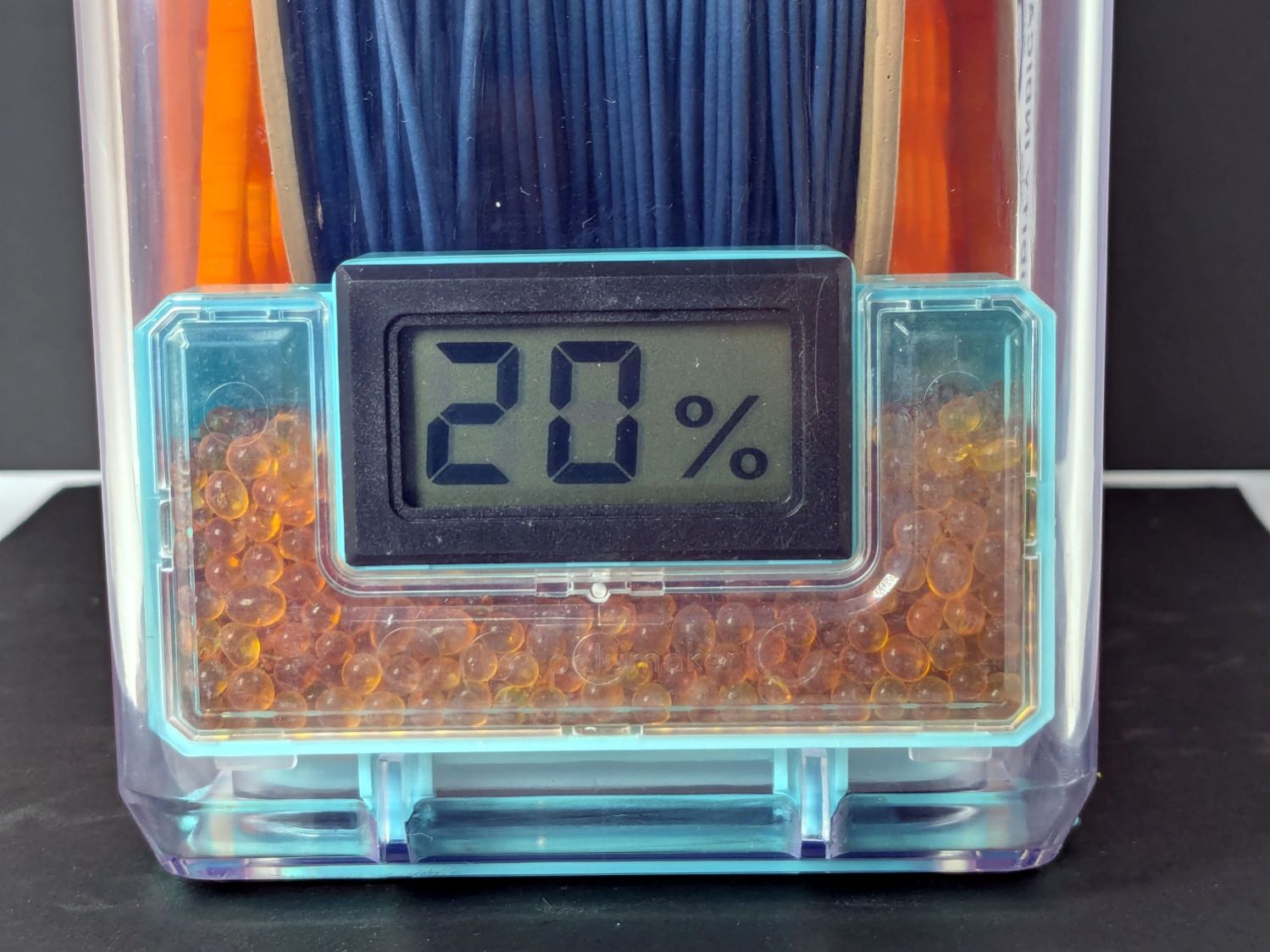
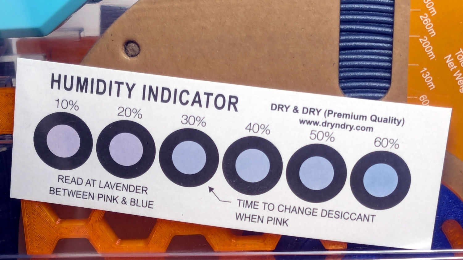
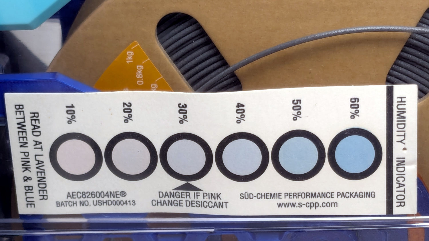
Black PETG, gain 0.8 g:
Polydryer – 21 pctRH – meter – black PETGPolydryer – 21 pctRH – card – black PETG
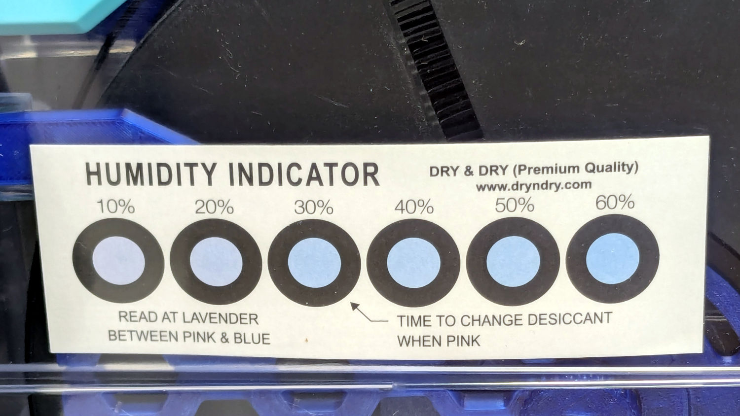
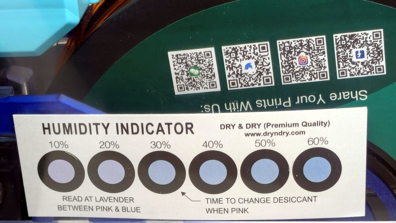
The (newer) indicator cards with the smaller dots / larger black borders seem less acute than the (older) large-dot cards. The two 28 %RH cards look about right, but the 20 and 21 %RH cards seem more different than the similar humidity would suggest.
Under 20 %RH, all the spots look pretty much the same, but AFAICT any humidity below 20 %RH is Good Enough for 3D printing.
The Blue PETG-CF went directly from its sealed bag into the PolyDryer box, unlike the Black and Gray PETG-CF spools that sat in the 50% RH basement long enough to soak up the ambience. The Blue has outgassed enough water to suggest spools do not arrive “bone dry” from the factory, although the Black and Gray prove the Basement Shop is wetter than the factory.
All of the silica gel together weighed 184.2 on the same scale I originally measured the 25 g quantities that should have totalled 175 g, but the individual measurements total 183.3 g. I don’t trust the scale to be better than ±0.1 g on any measurement, so half a percent is likely as good as it gets.
The silica gel weighed 187 g on the kitchen scale, sweated down to 179 g after 7 minutes in the microwave being defrosted like 1.5 pounds of fish, and, depending on which numbers you believe, released 8 to 10 g of water in the process.
Microwaving something containing so little water means the silica gel absorbs very little of the energy: the dish, glass turntable, and metal walls got absurdly hot. I think using the induction cooktop and cast iron pan makes more sense, even if it takes longer.
With fresh silica gel in place, perhaps waiting two weeks will produce interesting numbers.
A recent quilt photo shoot degenerated into me chasing several bright orange clamp jaws across the deck as they popped off their clamps hanging from the photo backdrop scaffold. Most clamps have jaws snapping onto actual rods, but these clamps have molded-in-place “rods” much smaller than the 2 mm expected by the jaws and much more irregular than seems reasonable.
Trace and scan the nose of a clamp:
Large spring clamp nose outline
Curiously, the molded rod is not centered in the nose:
Large spring clamp nose – pin locatIon
Use LightBurn to coerce a scan of the first sketch into a suitable path, laser-cut some MDF, and glue up a drill fixture:
Spring clamp jaw pins – fixture gluing
Align the drill to the center of the off-center hole marked on the bottom layer:
Spring clamp jaw pins – drill alignment
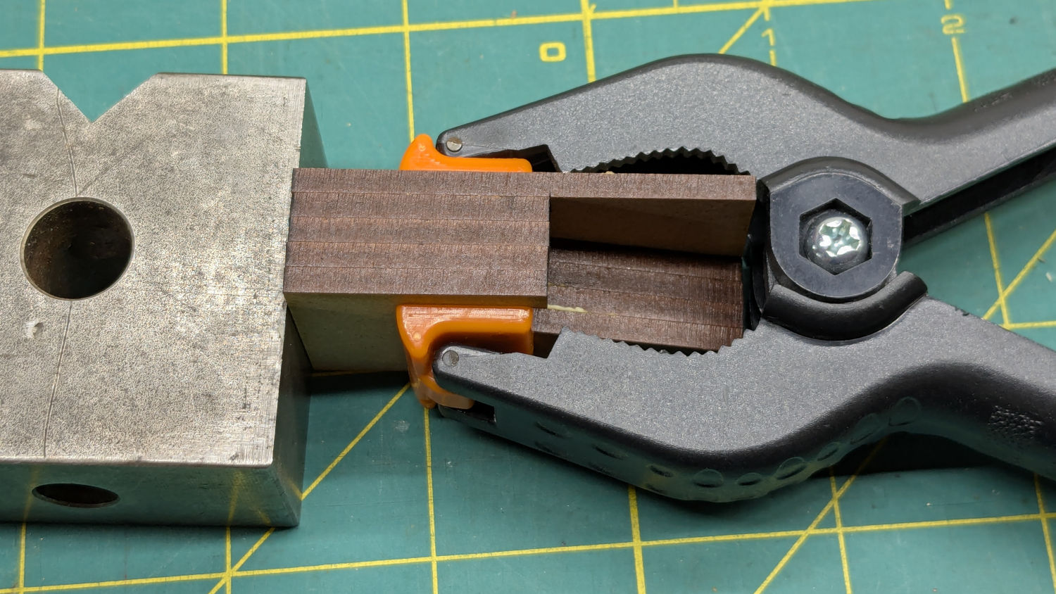
The drilling setup looks casual, but hand-holding the clamps against the rear wall and into the form-fitting nose recess sufficed:
Spring clamp jaw pins – fixture overview
I snipped the plastic “rods” out before drilling the holes, then rammed 2 mm steel rods in place:
Spring clamp jaw pins – steel
They’re really 5/64 inch = 1.98 mm rods from the oil-hardening drill rod stash, but entirely sufficient for the purpose.
With one clamp in hand, though, there was obviously no reason for the rods to be off-center. So I centered the drill in the nose, punctured the rest of the clamps, and pressed 2 mm carbon fiber rods in place:
Spring clamp jaw pins – steel vs carbon fiber
The rods were cut to 20 mm by rolling them across a pad with firm pressure from a utility knife. That was mostly to get some experience cutting carbon fiber, which is obviously overqualified for the job.
Snap the orange jaws in place and I shall never suffer the embarrassment of chasing them again …
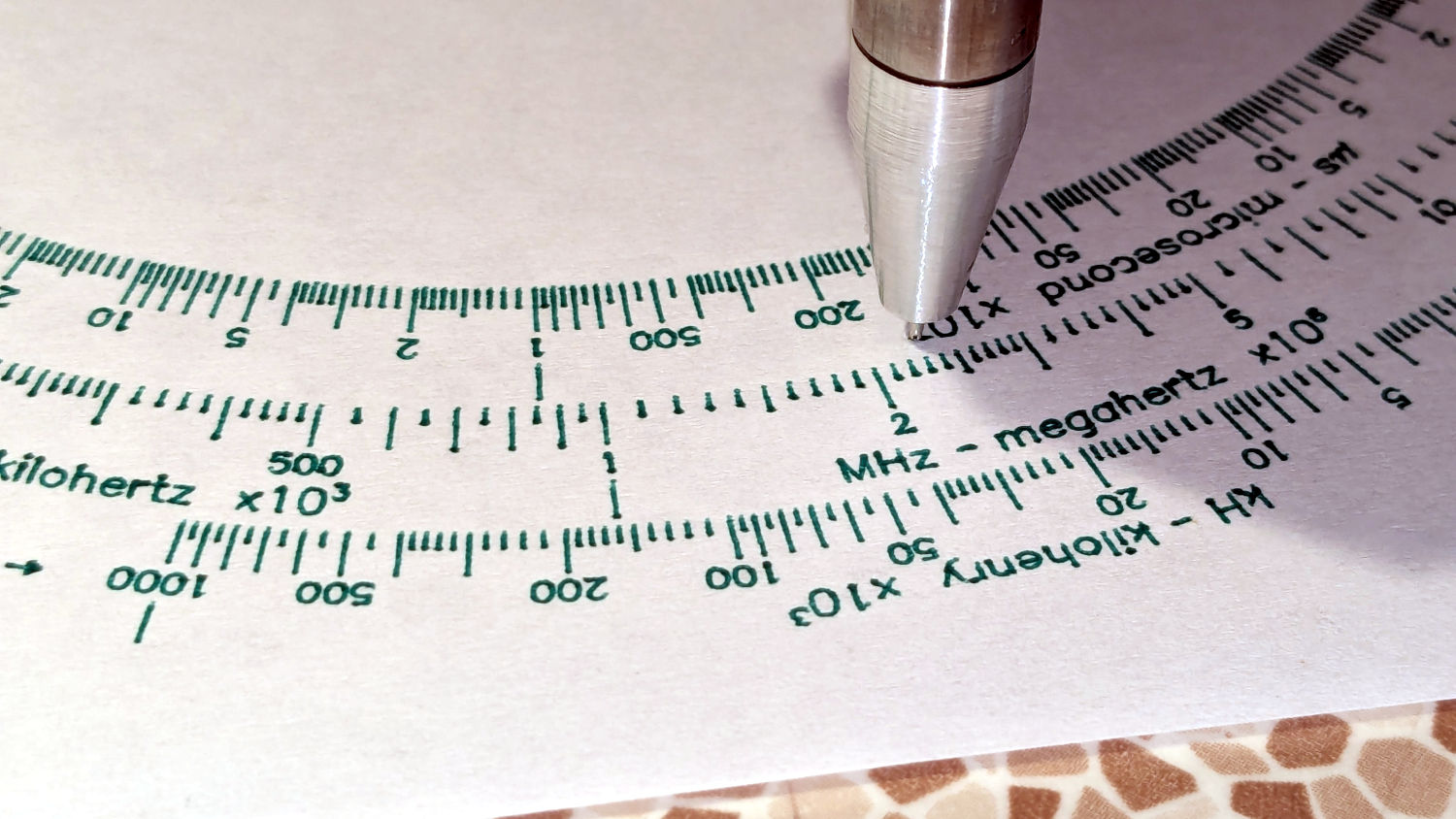
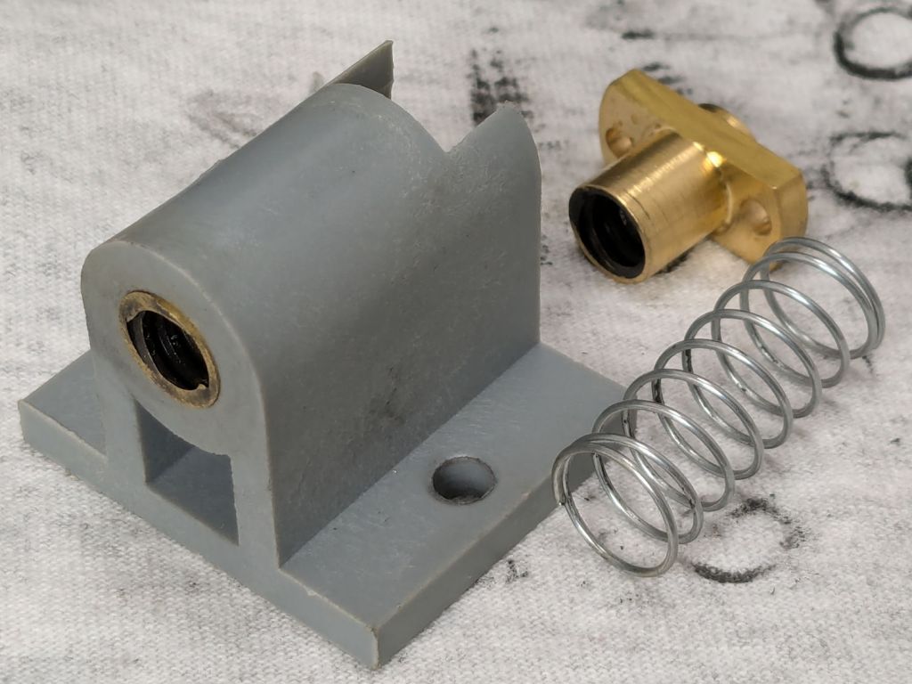
A confluence of unrelated events led me to unboxing and setting up the CNC-3018XL most recently used to plot Homage Tek Circuit Computer decks, but the table slid along its rods entirely too easily. A peek at the leadscrew revealed an assortment of parts last seen when I extended the frame:
3018CNC – table drive – as found
The featureless cylinder is the leadscrew follower nut, which evidently popped out of its proper place in the table drive block:
3018CNC – table drive parts
The crude chamfer suggests that end went into the block first, so that’s what I did:
3018CNC – table drive – follower nut installed
It seems snug enough in there, at least for a machine used solely for plotting and maybe drag knife cuttery, so I’ll assume the box received some rough handling during our move.
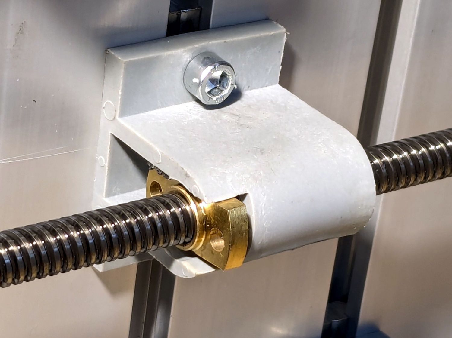
It’s now back in place and seems to work well enough:
3018CNC – table drive – installed
I briefly considered adding some setscrews to hold it in place, but came to my senses. If it pops out again, maybe it’ll be time to rebuild that block with proper retention.
The software side of the thing surely needs TLC, too.
Having accumulated a bunch of used activated alumina desiccant, I figured now was a good time to try regenerating it. Industrial applications use dry gas and very high temperatures, but perhaps holding it over 100 °C for a few hours will suffice for my purposes.
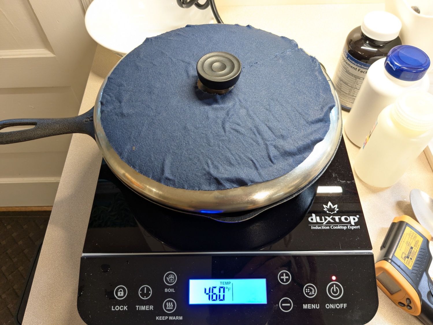
After an hour the surface temperature was around 150 °F, so I covered the pan with a water-cooled lid to see if any vapor condensed on it:
Alumina regeneration – lid cooling
It did, indeed, so I alternated covering and exposing the pan, which was likely a waste of my time, until the alumina dried enough that the lid didn’t collect any condensation. The whole process took just under four hours with the cooktop set to its maximum of 460 °F for most of the time.
The beads then cooled to room temperature in a covered dish:
Alumina regeneration – final cooling
The beads weighed 626 g at the start of the adventure and sweated down to 593 g, parting with 33 g = 1.2 oz of water in the process for a loss of 5.6%. I have no idea how dry they are now, but they’re an ounce drier than before.
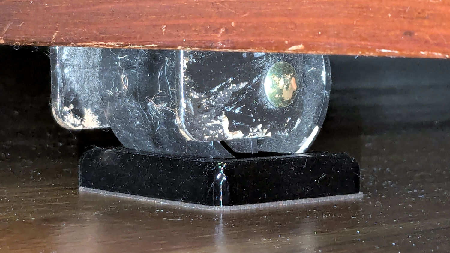
The upstairs Sewing Room came with a couch-like bed incorporating a roll-out trundle bed. It doesn’t get a lot of use, but it lacks wheel locks and tends to scoot away unless you get into it rather more carefully than seems reasonable.
So I made a pair of stops to capture the wheels:
Rolling Bed Stops – installed
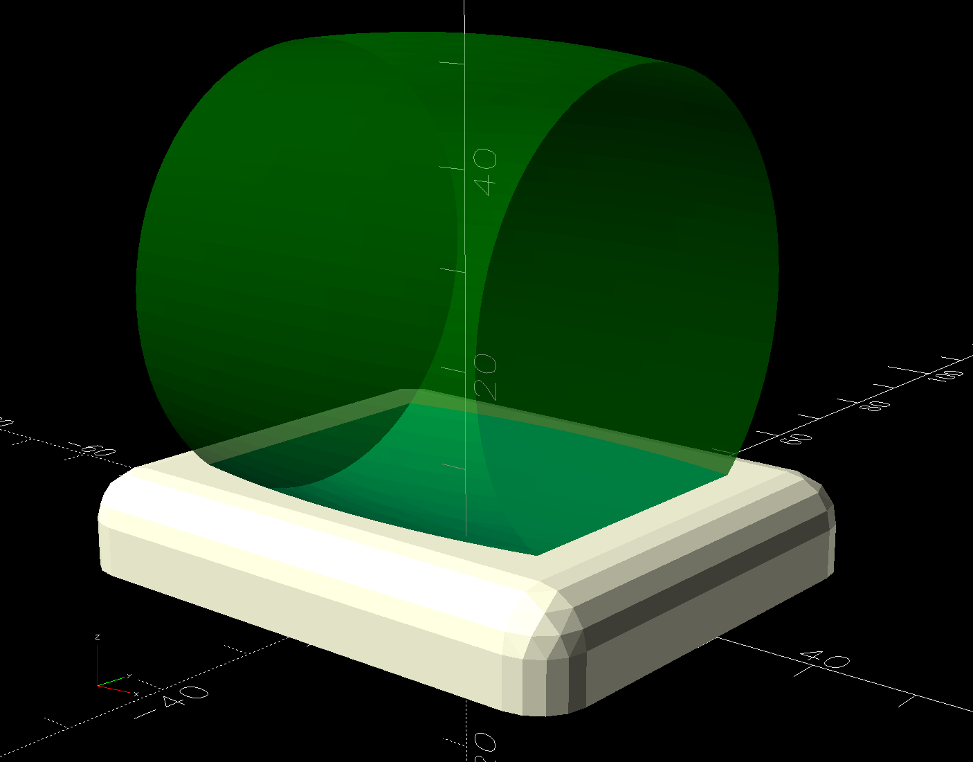
The solid model shows they’re just plastic blocks minus a model of the roller wheel:
Rolling Bed Stops – solid model – show view
I like the wood-grain effect of the doubly curved recess on printed plastic layers, even if nobody will ever see it:
Rolling Bed Stops – PrusaSlicer
The OpenSCAD code also exports a projection of the block as an SVG file to laser-cut the cork pad.
Roll the trundle bed into position, push the stops against the wheels, lift and pull forward an inch, let it down, and the wheels snap into those recesses.
These are considerably fancier than some of the other wheel stops / feet around the house, if only because I got to use the Chord Equation to solve for the radius of the circle parallel to the axle for a snug socket.
This file contains hidden or bidirectional Unicode text that may be interpreted or compiled differently than what appears below. To review, open the file in an editor that reveals hidden Unicode characters.
Learn more about bidirectional Unicode characters