Ed Nisley's Blog: Shop notes, electronics, firmware, machinery, 3D printing, laser cuttery, and curiosities. Contents: 100% human thinking, 0% AI slop.
The converted OttLite hit the floor again and, this time, the shell around the lamp popped free. Given that I didn’t know how to take it apart before, this is new news.
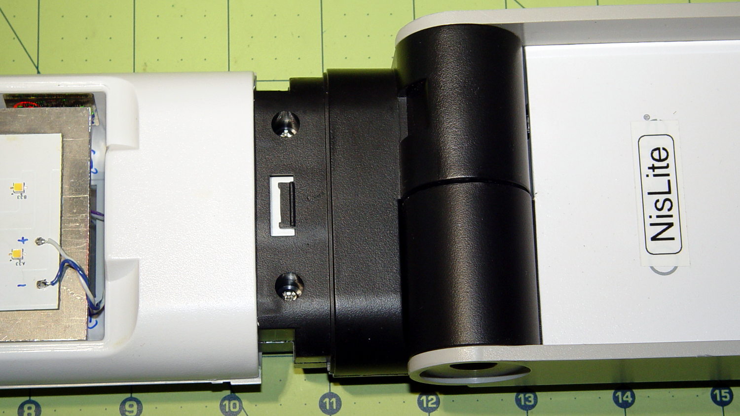
There’s a small snap latch inside the bottom / inner surface:
OttLite LED Conversion – lamp shell – ventral
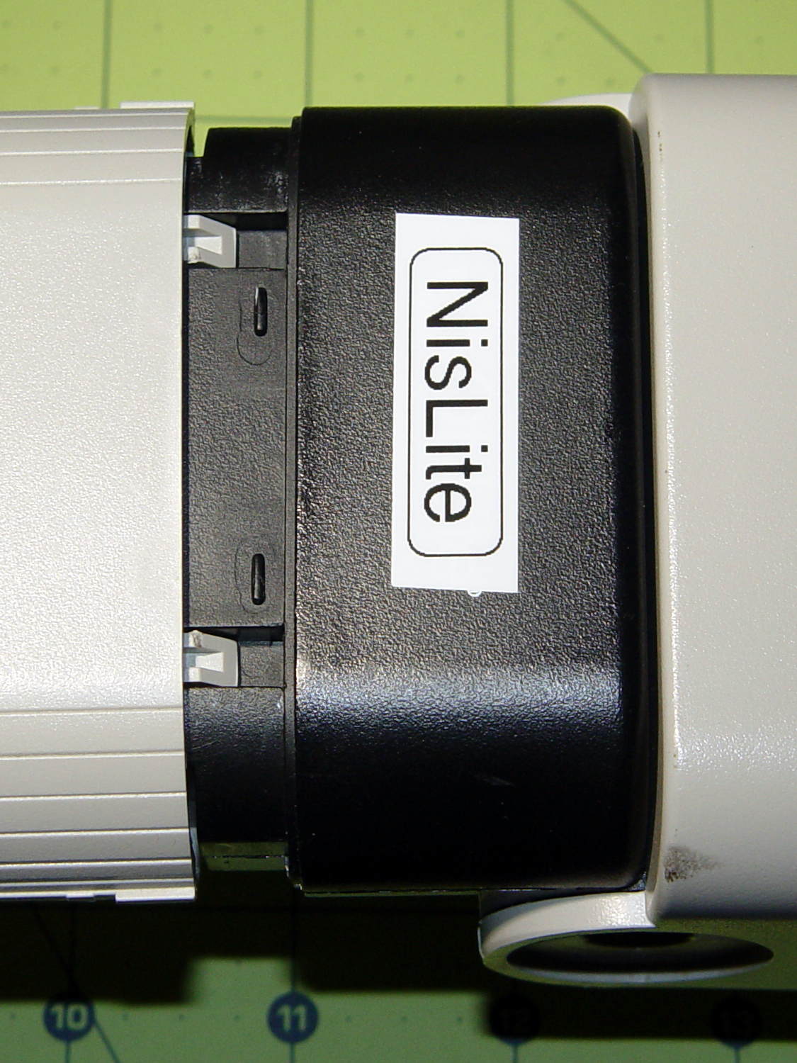
And two guide notches + latch nubs inside the top / outer surface:
OttLite LED Conversion – lamp shell – dorsal
So, if you had to get it apart by hand, a spudger-like tool applied to the bottom / inside of the shell and a bit of tugging should do the trick.
It snapped back together without incident, but I really must figure out a bigger base for the damn thing.
Mad Phil gave me his Brother PT-1090 labeler, which I’ve been using rather often of late. The white tape cartridge (the TZ flavor) ran out, giving me the opportunity to pry it apart:
Brother P-Touch TZ tape cartridge – disassembled
Surprisingly, a few small pins molded into the cover, plus a few obvious latches, hold it together without a trace of glue or thermal welding.
A detail of the little factory that assembles the label from several parts:
Brother P-Touch TZ tape cartridge – detail
Colored paper tape unwinds from the lower right and the top plastic layer from the lower left. Tape with thermal dye unspools from the upper left, the printhead (in the printer) heat-transfers pixels to the plastic tape in the opening right of center along the top, and the roller at the top right joins the just-printed plastic layer to the slightly sticky front surface of the paper tape. The used imaging tape respools in the gray cylinder near the middle.
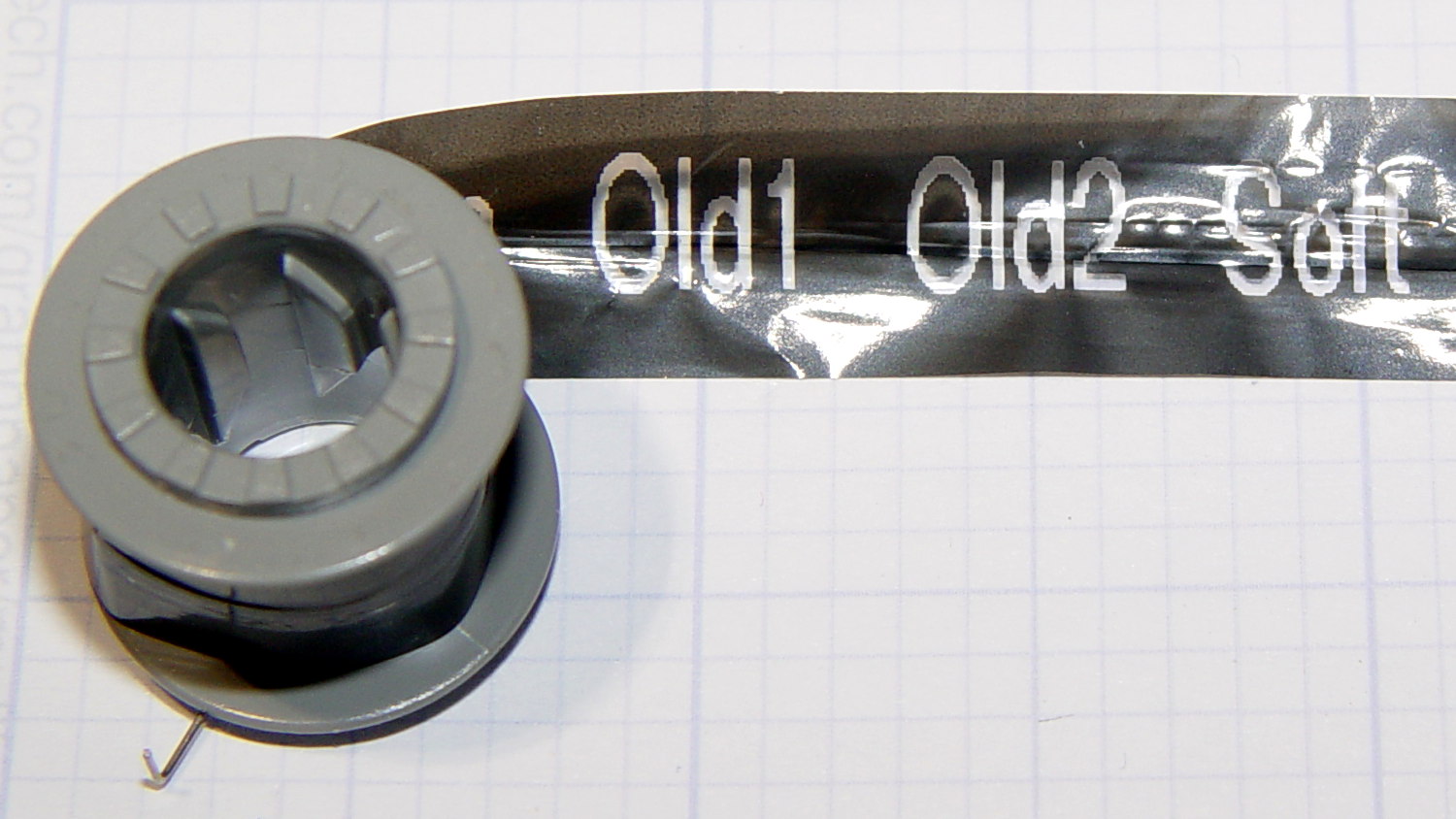
For those concerned with privacy, that gray spool of used imaging tape contains everything you’ve printed in order:
Brother P-Touch TZ tape cartridge – imaging tape
I thought the thermal dye was part of the transparent tape cover layer, but in retrospect that doesn’t make sense: the printed tape would turn black in hot environments like, say, your car. So the printer must transfer the dye from a separate tape.
The knockoff “ESD” tape cartridges from Amazon seem to have a slightly different tape path, probably to work around Brother’s patents. I’ll pry one of those apart in due course.
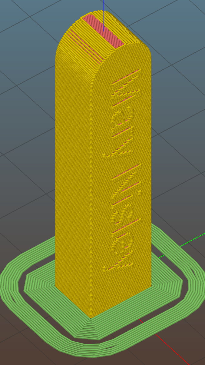
The side walls are two threads thick and, at least in PETG, entirely too rigid to slide on easily. I think a single-thread wall with a narrow ridge would provide more spring; if this one gets too annoying, I’ll try that.
This file contains hidden or bidirectional Unicode text that may be interpreted or compiled differently than what appears below. To review, open the file in an editor that reveals hidden Unicode characters.
Learn more about bidirectional Unicode characters
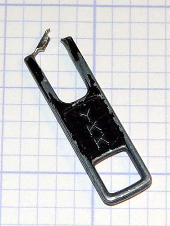
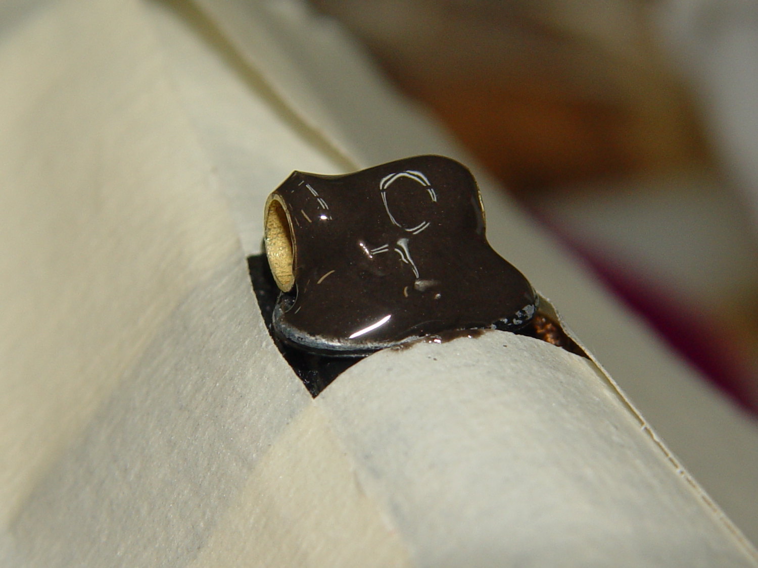
In our last episode, the zipper tab on my belt pack had worn through:
Eroded YKK Zipper Tab
I “fixed” that by the simple expedient of running a key ring through the latch that used to hold the tab. That held for half a year, which isn’t to be sniffed at for a zero-cost repair.
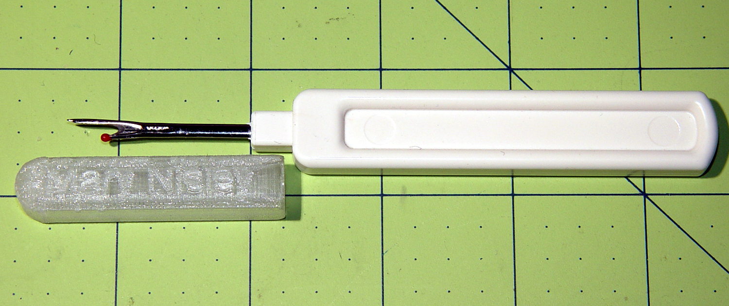
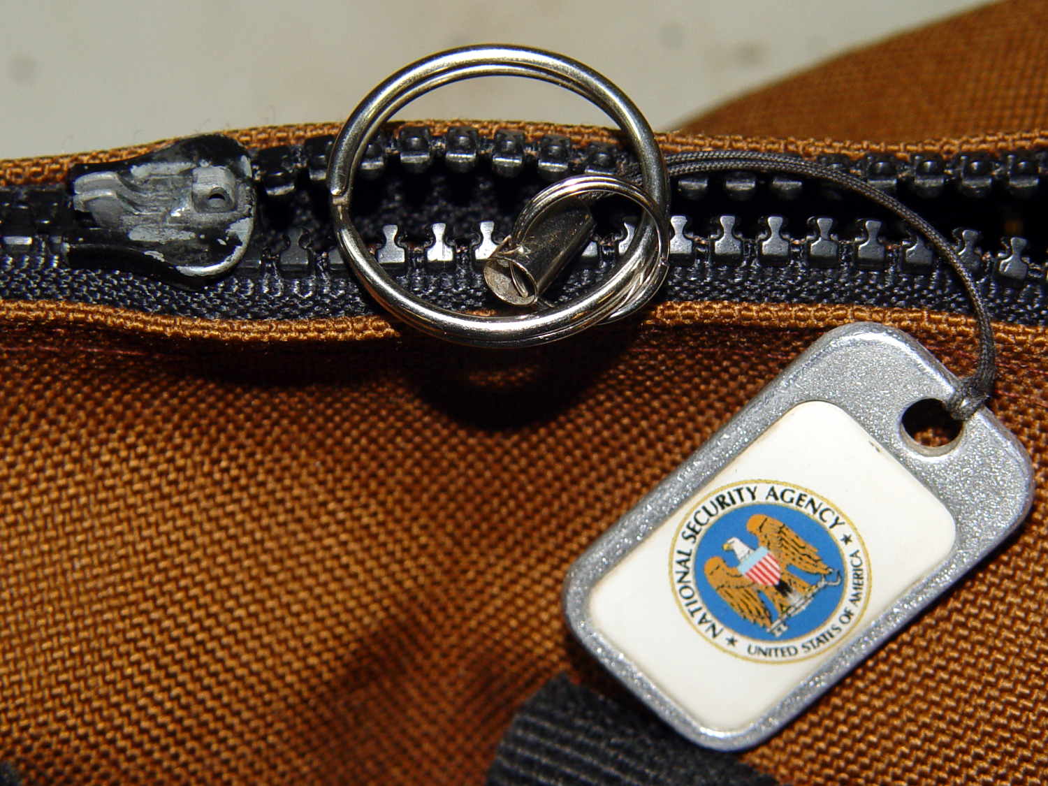
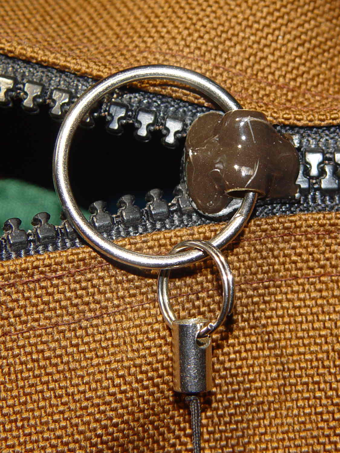
A few days ago, the abused latch popped off the slider, leaving the NSA tag and ring in my hand:
Belt Pack Zipper – missing tab and latch
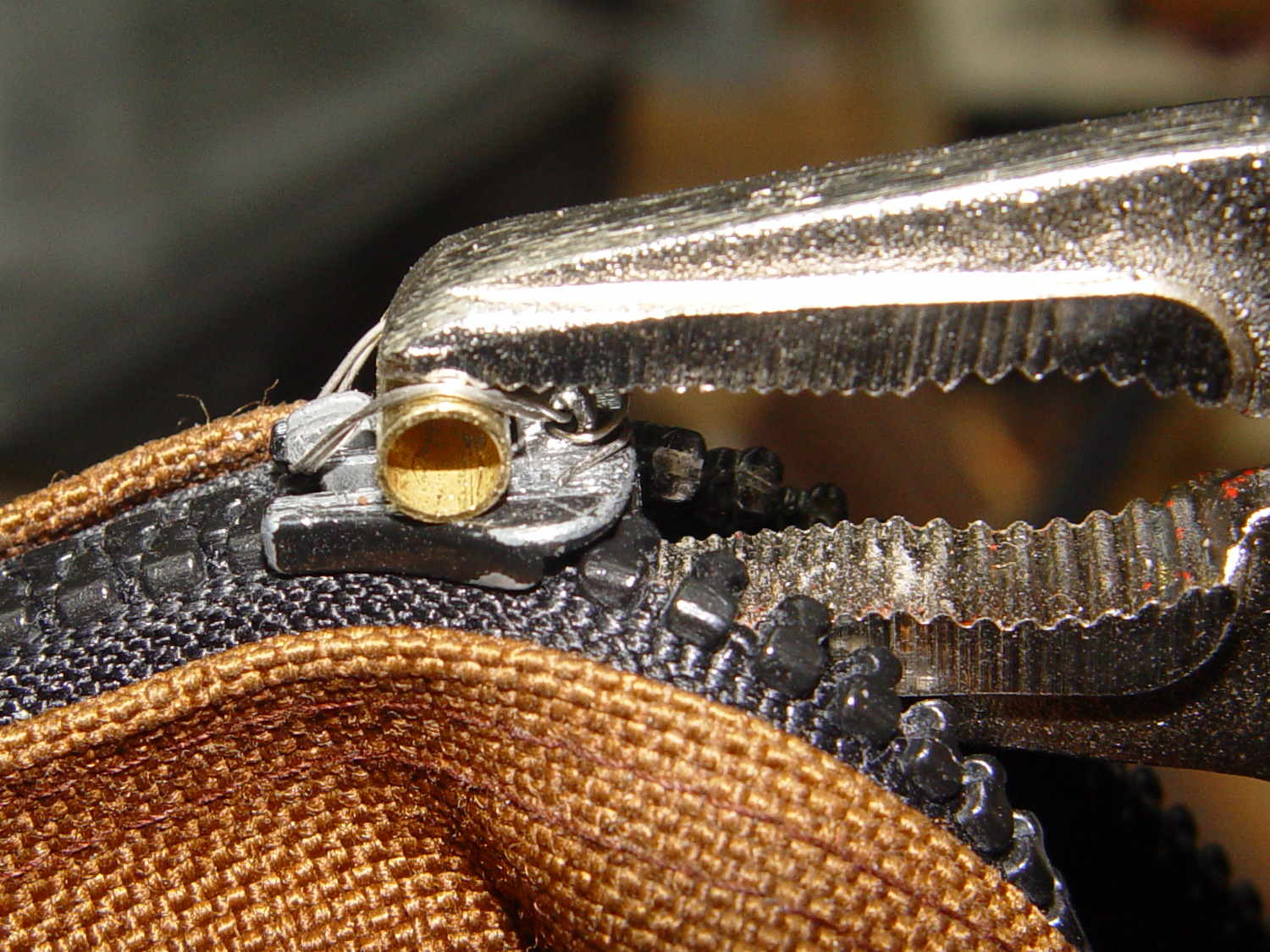
I scuffed up the surface with a file to provide a bit more grip for the inevitable epoxy, then clamped a brass tube athwart the slider:
Belt Pack Zipper – wired brass tube
The tube ID passes the ring with enough clearance to make it work out. The general idea is that the tube provides rigidity for the ring, the wires hold the tube against the pull, and the epoxy holds the wires in place. I fully expect the sharp edges around the tube’s ID will gradually wear away.
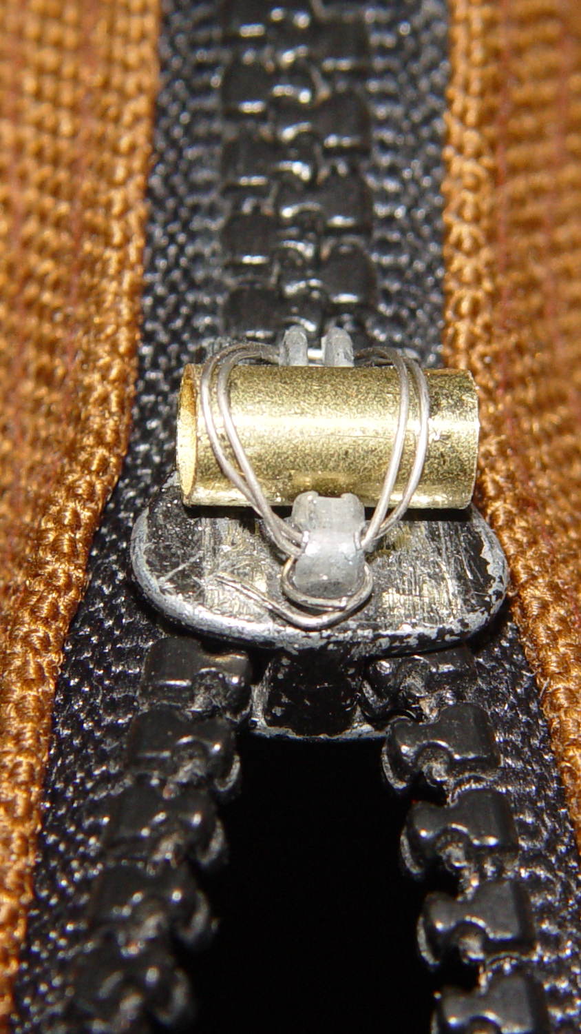
Threading 14 mil stainless steel wire through the slider’s pivot hole:
Belt Pack Zipper – wire opened end
… and under the latch guide:
Belt Pack Zipper – wire closed end
… required a few tries and produced some nasty puncture wounds, but eventually it all hung together long enough to let me tuck some JB Kwik epoxy into all the nooks and crannies:
Belt Pack Zipper – epoxy curing
That’s wide masking tape covering the work area. As it turned out, good preparation like that meant I didn’t slobber epoxy anywhere it shouldn’t go; had I omitted the tape, there’d be a smear down the side of the pack.
Fast-forward to the next morning and it’s all good:
Belt Pack Zipper – repaired
The missing latch locked the slider in place, but I think I can eke out a miserable existence with a loose slider…
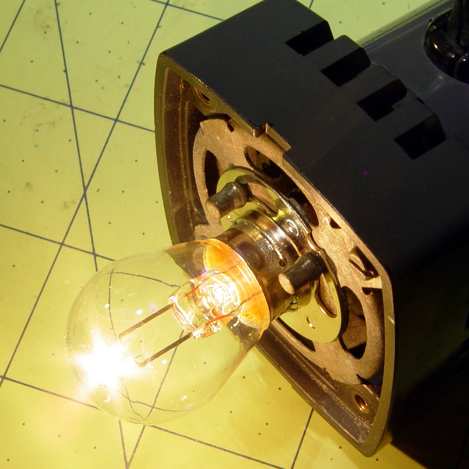
A classic American Optical microscope illuminator emerged from a box, minus its bulb. Some rummaging turned up a reference for AO bulbs, so I knew I needed a GE 1460 prefocused bulb. Those seem to be a bit rare these days, with 1460X bulbs sharing the same base with a slightly different glass envelope shape. As nearly as I can tell, as long as the filament sits in the same location relative to the base, it’s all good. Five bucks and a few days brought a new 1460X bulb to the bench, a few drops of Caig DeoxIT slicked the holder’s rather gritty contact patches, and the new bulb fit perfectly:
Microscope Illuminator – 1460X bulb – detail
And it lit up just fine, too:
Microscope Illuminator – 1460X bulb – turned on
That’s running at the lowest of three selectable voltages: 5, 6, and 7.5 VAC, respectively. Given that the bulb spec says 6.5 V (at 2.75 A!), you best have a spare bulb on hand if you need the highest setting. At the nominal 6.5 V, it’s good for 100 hours; 6 V should eke out many more hours.
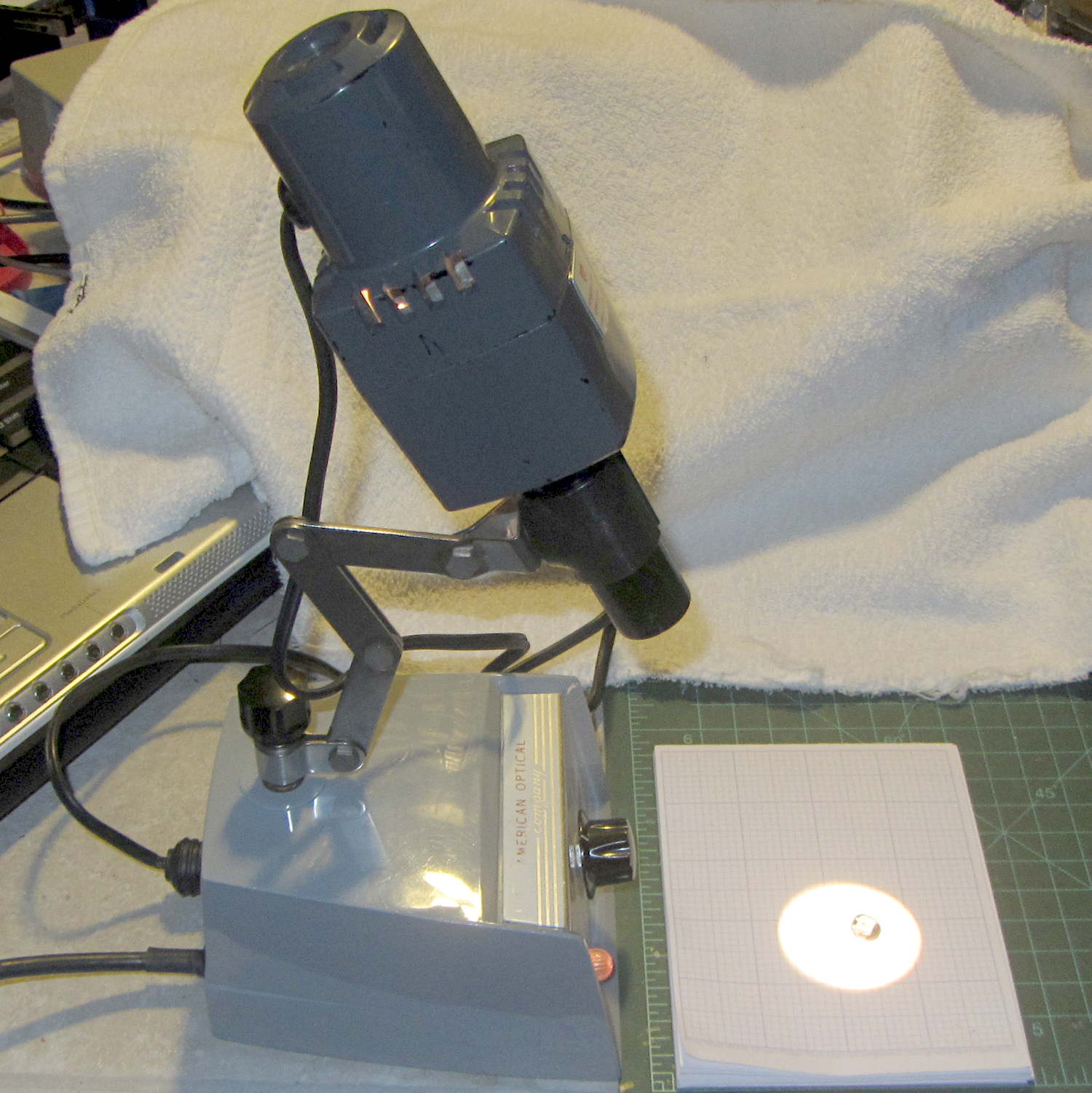
A generously articulated arm holds the illuminator for desk work:
American Optical Model 651 Microscope Illuminator – on base
That long snout fits into the pair of holes in the arm of my stereo zoom microscope to cast a bright light directly on the subject. The LED ring light makes that less necessary than before, although sometimes distinct shadows help pick out the details:
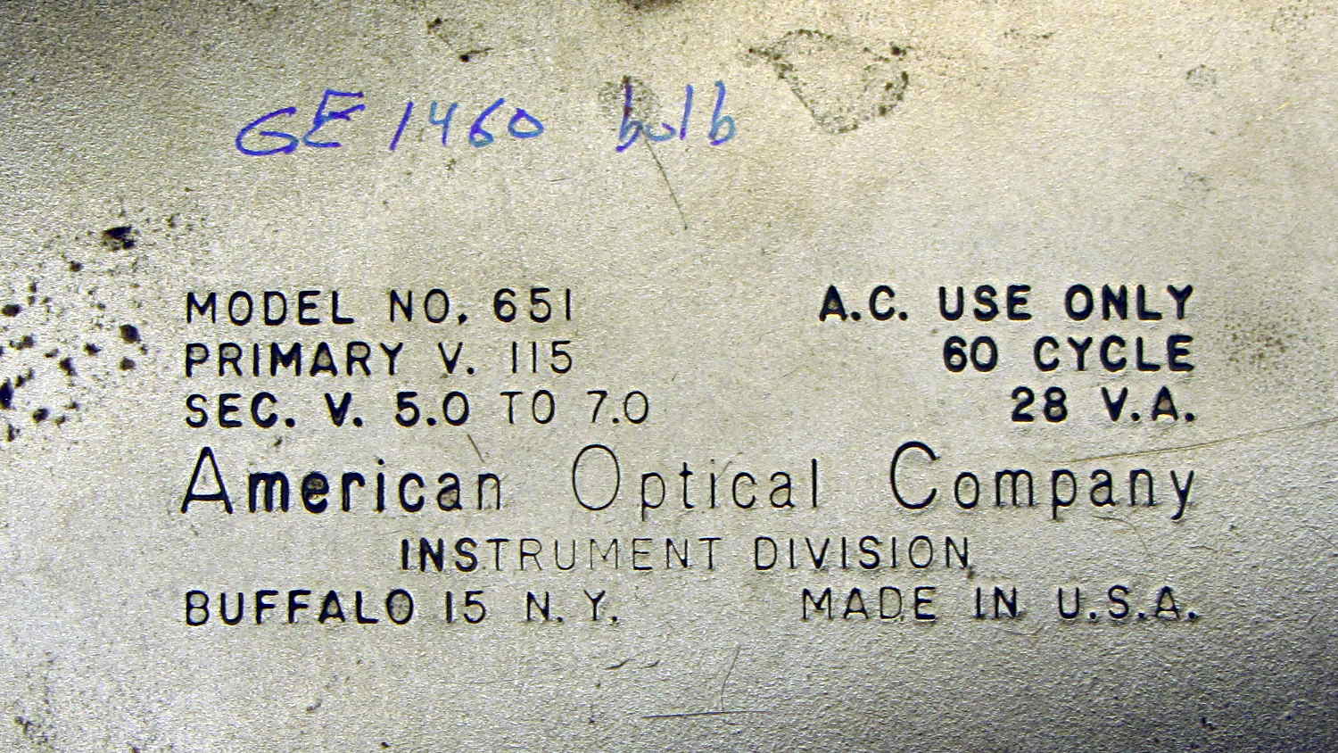
The data plate on the bottom of the illuminator, should someone need it:
American Optical Model 651 Microscope Illuminator – data plate
The optics cast an image of that white-hot filament out into space, so I think the diffuse active area of a white LED wouldn’t produce the same amount of light on the target. I have some Pirhana LEDs, though, so (when this bulb fails) I’ll see about that.
So I found two copies of the US Army’s Demolition Card GTA 5-10-9 tucked under a row of completely unrelated books in the Basement Laboratory (clicky for more dots):
One can only hope it’s slightly more useful than the Calculator Set, Nuclear, M28 — FSN 6665-897-8697 on another shelf. It dates back to the era when you could get ammonium nitrate that went blam when prompted; rumor has it that retail fertilizer now comes with built-in detonation inhibitors.
Essentially all adult human males have a story including the phrase “but for an (inch | second), I wouldn’t be here” … it’s a survivor bias thing.
As part of replacing the entire drivetrain on my Tour Easy, I finally got around to replacing the bearings in the Phil Wood rear hub. The rear axle supports four bearings, with the innermost one captured between the end of the freehub and the aluminum retainer:
Phil Wood hub – internal bearing
The three small screws secure the retaining ring (sitting off to the right) against the bearing. If you don’t know what’s inside, you’d think they hold the freehub in place. Removing them doesn’t do anything useful unless you’re replacing the bearings and, if the retainer rotates even slightly inside the hub, you’re faced with taking the whole damn thing apart.
That bearing is lightly loaded, well-protected on all sides, and felt just fine, so I slathered more grease around it and left it in place. The other three bearings hit the trash can with a resounding clang…