The Smell of Molten Projects in the Morning

Ed Nisley's Blog: Shop notes, electronics, firmware, machinery, 3D printing, laser cuttery, and curiosities. Contents: 100% human thinking, 0% AI slop.

Category: Machine Shop

Mechanical widgetry

  • Fordham FG-801 Function Generator Power Switch

    The power switch in my trusty Fordham FG-801 Function Generator failed with an accumulation of oxidation / crud on the contacts. That’s fix-able, but the switch contained not one, but two powerful springs, and puked its guts all over the floor around the Squidwrench Operating Table. Even with (a preponderance of) the parts in hand, I couldn’t figure out how to reassemble the thing; the only way out was to replace the switch.

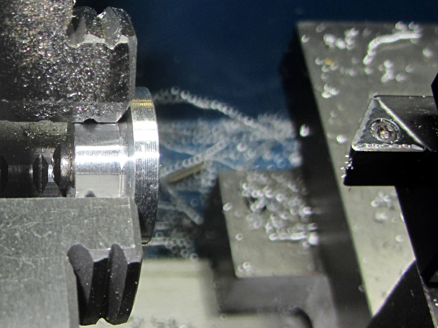
    The OEM switch had a 0.360+ inch diameter pushbutton that fit into a ⅜ inch hole and, alas, my remaining stock of line-voltage switches had toggle levers and used ¼ inch holes. So I converted a bit of aluminum rod into a suitable bushing:

    Fordham FG-801 Fn Gen - new switch hardware
    Fordham FG-801 Fn Gen – new switch hardware

    The lock washer in the middle started with a much wider tab that I filed down into a tooth for the dent from a #2 center drill. Protip: center drills don’t walk off like twist drills, even when you hand-hold the front panel at the drill press with all the electronics dangling below.

    The bushing dimension doodle:

    Fordham FG-801 Function Generator - Replacement Switch Bushing
    Fordham FG-801 Function Generator – Replacement Switch Bushing

    The internal wiring routes the 120 VAC line conductor to the switch, then to the fuse, then to the transformer. I don’t know whether it’s better to have an unfused switch or an unswitched fuse (surely there’s a UL spec for that), but I didn’t change anything. The new switch, being slightly smaller and mounting directly on the panel, required a new wire (the blue one) from the fuse:

    Fordham FG-801 Fn Gen - power switch - installed
    Fordham FG-801 Fn Gen – power switch – installed

    The OEM switch mounted on two round brass standoffs and, wonder to tell, the new switch fit between them!

    From the front, the new switch looks like it grew there:

    Fordham FG-801 Fn Gen - switch in action
    Fordham FG-801 Fn Gen – switch in action

    The PCB mounts to the top of the case with one screw and four hexagonal brass standoffs. The standoffs have 6-32 tapped holes on one end and a 6-32 stud on the other; one of those stud had broken off. A 6-32 stainless steel screw secured in a clearance hole with a dab of epoxy solved that problem:

    Fordham FG-801 Fn Gen - standoff stud
    Fordham FG-801 Fn Gen – standoff stud

    I stood it vertically and tweaked the screw to be perpendicular while the epoxy cured.

    Memo to Self: The next time around, put a nut on the stud to make sure the answer comes out right. I didn’t do this time to avoid epoxying the nut to the standoff.

    Done!

  • Loop Antenna Splice Reinforcement

    Those solder joints and finicky little wires seem much too fragile on their own:

    LF Loop Antenna - complete joint
    LF Loop Antenna – complete joint

    This should help:

    Loop Antenna Splice - assembled
    Loop Antenna Splice – assembled

    Foam blocks hold the ribbon cable in place and provide a bit of strain relief around the hard plastic edge:

    Loop Antenna Splice - hardware
    Loop Antenna Splice – hardware

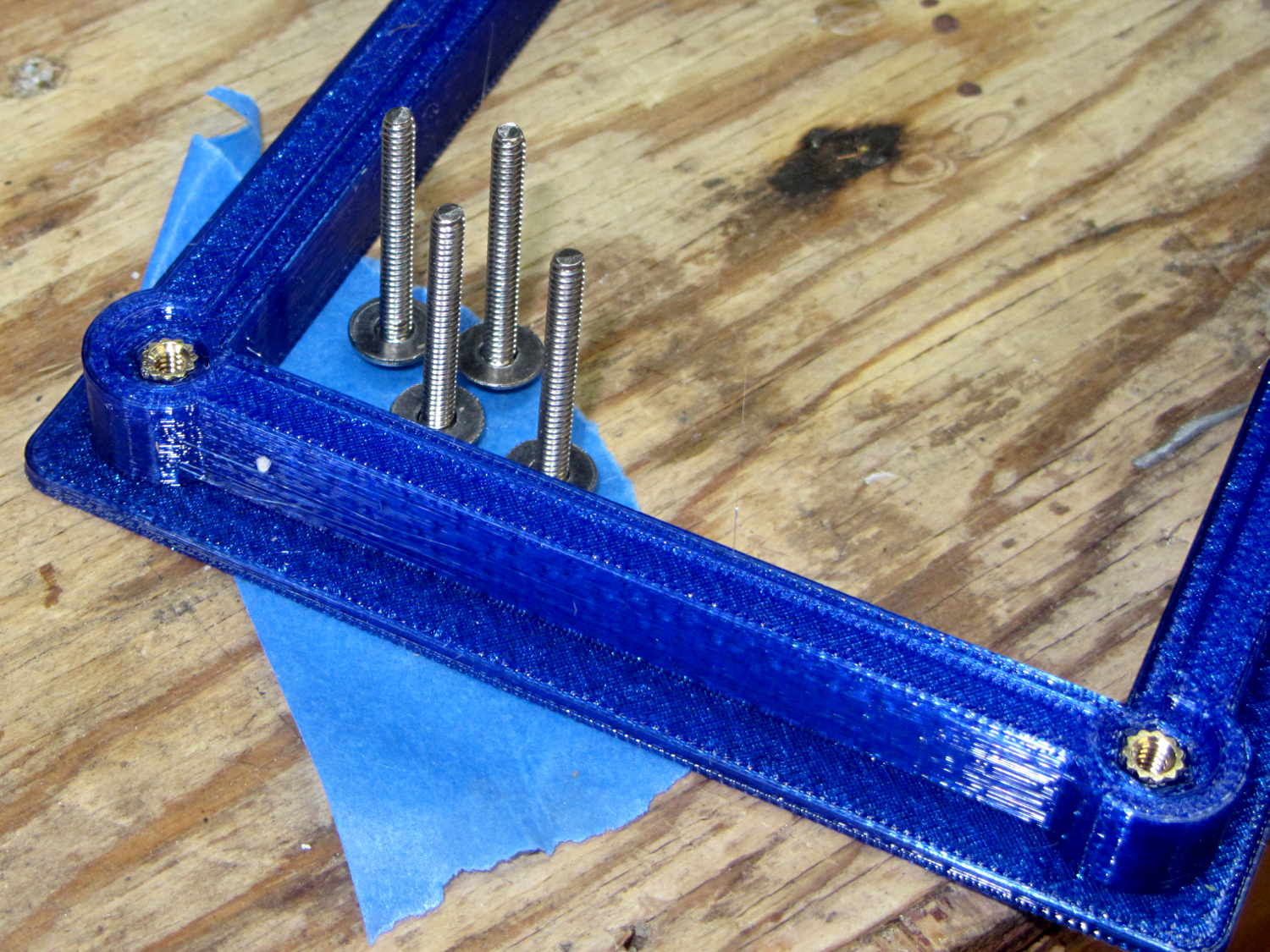
    The brass inserts in the bottom block (on the left) got epoxied in place, because they must provide quite a bit of force to clamp the foam. Their larger knurled end sits flush with the outside surface and the smaller end has one thread thickness of clearance below the inner surface.

    A last look at the wiring:

    Loop Antenna Splice - wiring
    Loop Antenna Splice – wiring

    I think the preamp must sit at some distance from the antenna to prevent feedback, but that remains to be seen.

    The M2’s nozzle accumulated a huge blob of PETG that turned into a giant smear:

    Loop Antenna Splice - PETG booger
    Loop Antenna Splice – PETG booger

    Fortunately, it’s on the inside where nobody will ever see it. If you know where to look, it’s barely visible from the outside.

    The solid model shows off the structure a bit better:

    Loop Antenna Splice - show view
    Loop Antenna Splice – show view

    The inside view:

    Loop Antenna Splice - bottom
    Loop Antenna Splice – bottom

    The OpenSCAD source code as a GitHub Gist:

    // Ribbon cable loop antenna splice
    // Ed Nisley KE4ZNU December 2016
    Layout = "Text";
    //- Extrusion parameters must match reality!
    ThreadThick = 0.25;
    ThreadWidth = 0.40;
    HoleWindage = 0.2;
    Protrusion = 0.1; // make holes end cleanly
    inch = 25.4;
    function IntegerMultiple(Size,Unit) = Unit * ceil(Size / Unit);
    //———-
    // Dimensions
    Cable = [200,48.0,1.5]; // X = longer than anything else
    Splice = [15.0,53.0,5.0]; // epoxy blob around joints
    Foam = [15.0,Splice[1],2.0];
    CornerRadius = 5.0;
    ID = 0;
    OD = 1;
    LENGTH = 2;
    Insert = [3.9,4.6 – 0.1,5.8]; // 4-40 knurled brass insert
    Screw = [2.7,5.5,2.0]; // OD = head LENGTH = head thickness
    Washer = [3.0,8.0,0.8];
    BlockOA = [60.0, // convenient length
    Splice[1] + 4*Washer[OD], // clearance around washer on top
    2*(Insert[LENGTH] + 2*ThreadThick)]; // insert sets both thicknesses
    NumScrews = 2; // screws along each side of cable
    ScrewOC = [BlockOA[0] / NumScrews,
    BlockOA[1] – 2*Washer[OD],
    2*BlockOA[2] // ensure complete holes
    ];
    TextThick = 3*ThreadThick; // depth of text into surface
    TextFit = HoleWindage/2; // clearance around text polygons
    //———————-
    // Useful routines
    module PolyCyl(Dia,Height,ForceSides=0) { // based on nophead's polyholes
    Sides = (ForceSides != 0) ? ForceSides : (ceil(Dia) + 2);
    FixDia = Dia / cos(180/Sides);
    cylinder(d=(FixDia + HoleWindage),h=Height,$fn=Sides);
    }
    //—–
    // Blocky model of cable + splice + wire tap for subtraction
    module Antenna() {
    union() {
    cube(Cable,center=true);
    cube(Splice,center=true);
    for (i=[-1,1])
    translate([0,-Splice[1]/2,0])
    cube([Splice[0]/2,Splice[1],2*Foam[2]],center=true);
    }
    }
    // Outside shape of splice Block, less screw clearance
    module SpliceBlock() {
    difference() {
    hull()
    for (i=[-1,1], j=[-1,1])
    translate([i*(BlockOA[0]/2 – CornerRadius),j*(BlockOA[1]/2 – CornerRadius),-BlockOA[2]/2])
    cylinder(r=CornerRadius,h=BlockOA[2],$fn=4*8);
    for (i = [0:NumScrews – 1], j=[-1,1])
    translate([-BlockOA[0]/2 + ScrewOC[0]/2 + i*ScrewOC[0],j*ScrewOC[1]/2,-(BlockOA[2]/2 + Protrusion)])
    PolyCyl(Screw[ID],BlockOA[2] + 2*Protrusion,6);
    }
    }
    // Splice block less cable
    module ShapedBlock() {
    difference() {
    SpliceBlock();
    Antenna();
    }
    }
    // Bottom
    module BottomPlate() {
    difference() {
    ShapedBlock();
    translate([0,0,BlockOA[2]/2])
    cube(BlockOA + 2*[Protrusion,Protrusion,0],center=true);
    Antenna(Splice);
    for (i = [0:NumScrews – 1], j=[-1,1])
    translate([-BlockOA[0]/2 + ScrewOC[0]/2 + i*ScrewOC[0],j*ScrewOC[1]/2,-(BlockOA[2]/2 + Protrusion)])
    PolyCyl(Insert[OD],2*Insert[LENGTH],6);
    for (i=[-1,1])
    translate([i*((BlockOA[0] – Foam[0] + Protrusion)/2),0,(BlockOA[2]/2 – Cable[2]/2 – Foam[2])])
    cube([Foam[0] + Protrusion,Foam[1],BlockOA[2]],center=true);
    }
    }
    // Top
    module TopPlate() {
    difference() {
    ShapedBlock();
    translate([0,0,-BlockOA[2]/2])
    cube(BlockOA + 2*[Protrusion,Protrusion,0],center=true);
    Antenna(Splice);
    for (i=[-1,1])
    translate([i*((BlockOA[0] – Foam[0] + Protrusion)/2),0,-(BlockOA[2]/2 – Cable[2]/2 – Foam[2])])
    cube([Foam[0] + Protrusion,Foam[1],BlockOA[2]],center=true);
    rotate(90) {
    translate([0,6,BlockOA[2]/2 – TextThick])
    TextHack("KE4ZNU",8,0.0,1.15,TextThick + Protrusion);
    translate([0,-6,BlockOA[2]/2 – TextThick])
    TextHack("2016·12",6,0.0,1.20,TextThick + Protrusion);
    }
    }
    }
    module TextHack(Text="sample",Size=10,Offset=0.0,Space=1.0,Thick=ThreadThick) {
    linear_extrude(height=Thick,convexity=10)
    offset(r=Offset)
    text(Text,font=":bold",size=Size,spacing=Space,halign="center",valign="center");
    }
    //———-
    // Build them
    if (Layout == "Antenna")
    Antenna();
    if (Layout == "SpliceBlock")
    SpliceBlock();
    if (Layout == "ShapedBlock")
    ShapedBlock();
    if (Layout == "Bottom")
    BottomPlate();
    if (Layout == "Top")
    TopPlate();
    if (Layout == "Text") {
    translate([0,6,0])
    TextHack("KE4ZNU",8,-TextFit,1.15,TextThick);
    translate([0,-6,0])
    TextHack("2016·12",6,-TextFit,1.20,TextThick);
    }
    if (Layout == "Show") {
    translate([0,0,5])
    TopPlate();
    translate([0,0,-5])
    BottomPlate();
    color("Orange",0.2)
    Antenna();
    }
    if (Layout == "Build") {
    translate([0,-0.6*BlockOA[1],BlockOA[2]/2])
    rotate([180,0,0])
    TopPlate();
    translate([0,0.6*BlockOA[1],BlockOA[2]/2])
    BottomPlate();
    }
  • Snowthrower Shear Bolts

    The snowthrower (I’ve always called it a snowblower, but that’s just me) ate a ski pole (*), handle-tether-end first, and the right-side shear bolt worked perfectly when the right-hand auger slammed to a stop. A bit of drift punch rapping extracted the sorry lump at the bottom:

    Sheared MTD Snowthrower Bolts
    Sheared MTD Snowthrower Bolts

    The missing nut and bolt head may eventually surface, but I’m not losing any sleep over them.

    I popped a replacement shear bolt from the heap (thank you, Aitch!) and thought the nut went on rather stiffly. The nuts have a crimp in the middle to make them vibration-proof, but this one seemed stiffer than usual and, lo and behold, the bolt snapped just before I thought the nut had gotten far enough.

    The nut on the second replacement shear bolt required much less torque, didn’t (let me) snap the bolt, and I finished the mission. That’s the third or fourth shear bolt I’ve used since getting the thrower in 2007, so there’s a package of six in transit.

    Part Number 710-0809A, 5/16-18 x 1.5 inch.

    (*) One of Mary’s gardening cronies works for a sporting goods store, has access to an unlimited supply of slightly bent ski poles, and shares the bounty for use as garden stakes.

  • Under-cabinet Lamp Brackets: Close-fit Power Plug

    Adding a little tab to the angled brackets prevents them from pivoting while you’re tightening the mounting screw into the brass insert:

    Kitchen Light Bracket - angled lip - Slic3r preview
    Kitchen Light Bracket – angled lip – Slic3r preview

    The trick with those tabs is to chop ’em off halfway to the tip, because there’s no point trying to print a wedge that ends with a sharp edge:

    Kitchen Light Bracket - angled - tab cutoff - solid model
    Kitchen Light Bracket – angled – tab cutoff – solid model

    Generating & positioning that block goes a little something like this:

    translate([0,
               2*MountBlock[1] - LEDEndBlock[2]*sin(StripAngle),
               MountBlock[2]/2 + MountHeight - 0.5*LEDEndBlock[2]*cos(StripAngle)])
        cube(2*MountBlock,center=true);


    As a rule of thumb, there’s no point in fussing with smaller shapes when a big one will suffice…

    This LED strip fits under the cabinet over the butcher block countertop next to the stove, which turns out to be Just Barely longer than the strip itself:

    Under-cabinet light - cramped power plug
    Under-cabinet light – cramped power plug

    The OEM straight-on coaxial plug (near the bottom of the picture) attached to the wall wart cable obviously wouldn’t fit in the available space, so I gimmicked up a right-angle adapter by the simple expedient of shortening the solder lugs of a plug from the heap (which, admittedly, doesn’t quite fully seat in the socket), bending them sideways, soldering a pair of wires, heatshrinking appropriately, then coating wires + plug with JB Kwik epoxy. The other end of the wires gets a coaxial jack that miraculously fits the OEM plug, styled up with more heatshrink tubing. Not pretty, but nobody will ever see it.

    Unlike the LED strip under the other cabinet, this IR proximity sensor doesn’t mind having a wood edge next to it and, thus, didn’t need a strip of tape to keep it happy.

  • Under-cabinet Lamp Brackets: Angled Edition

    The LED strip lights have a reasonably diffuse pattern with an on-axis bright area that puts more light on the rear of the counter than seems strictly necessary. Revising the original brackets to tilt the strips moves the bright patch half a foot forward:

    Kitchen Light Bracket - angled - solid model
    Kitchen Light Bracket – angled – solid model

    For lack of anything smarter, the angle puts the diagonal of the LED strip on the level:

    Kitchen Light Bracket - angled - Slic3r preview
    Kitchen Light Bracket – angled – Slic3r preview

    The translucent block represents the strip (double-thick and double-wide), with a peg punching a hole for the threaded brass insert.

    Although the source code has an option to splice the middle blocks together, it can also build them separately:

    Kitchen Light Bracket - angled - LED block
    Kitchen Light Bracket – angled – LED block

    Turns out they’re easier to assemble that way; screw ’em to the strips, then screw the strips to the cabinet.

    I moved the deck screw holes to the other end of the block, thus putting the strips against the inside of the cabinet face. It turns out the IR sensor responds to the DC level of the reflected light, not short-term changes, which meant the reflection from the adjacent wood blinded it to anything waved below. Adding a strip of black electrical tape killed enough of the reflected light to solve that problem:


    Under-cabinet light - IR sensor shield
    Under-cabinet light – IR sensor shield

    The tape isn’t quite as far off-center as it looks, but I’m glad nobody will ever see it …

    The before-and-after light patterns, as viewed on B-size metric graph paper centered on the left-hand strip and aligned with the belly side of the countertop:

    Under-cabinet light - straight vs angled patterns
    Under-cabinet light – straight vs angled patterns

    Those look pretty much the same, don’t they? So much for photography as evidence for anything.

    The OpenSCAD source code as a GitHub Gist:


    // Mounting brackets for eShine under-counter LED lights
    // Ed Nisley KE4ZNU December 2016
    Layout = "Build";
    //- Extrusion parameters must match reality!
    ThreadThick = 0.25;
    ThreadWidth = 0.40;
    HoleWindage = 0.2;
    Protrusion = 0.1; // make holes end cleanly
    inch = 25.4;
    function IntegerMultiple(Size,Unit) = Unit * ceil(Size / Unit);
    //———-
    // Dimensions
    MountHeight = (1 + 0*3/16) * inch; // distance from cabinet bottom
    THREADOD = 0;
    HEADOD = 1;
    LENGTH = 2;
    WoodScrew = [4.0,8.3,41]; // 8×1-5/8 Deck screw
    WoodScrewRecess = 3.0;
    WoodScrewMargin = 1.5 * WoodScrew[HEADOD]; // head OD + flat ring
    Insert = [3.9,4.6,5.8 + 2.0]; // 4-40 knurled brass insert
    JoinerLength = 19.0; // joiner between strips
    LEDEndBlock = [11.0,28.8,9.5]; // LED plastic end block
    LEDScrewOffset = [1.0,8.2,0]; // hole offset from end block center point
    StripAngle = atan2(LEDEndBlock[2],LEDEndBlock[1]);
    echo(str("Strip angle: ",StripAngle));
    MountBlock = [WoodScrewMargin,(WoodScrewMargin + LEDEndBlock[1]*cos(StripAngle)),MountHeight];
    //———————-
    // Useful routines
    module PolyCyl(Dia,Height,ForceSides=0) { // based on nophead's polyholes
    Sides = (ForceSides != 0) ? ForceSides : (ceil(Dia) + 2);
    FixDia = Dia / cos(180/Sides);
    cylinder(d=(FixDia + HoleWindage),h=Height,$fn=Sides);
    }
    //—–
    // LED end block with positive insert for subtraction
    // returned with mounting hole end of strip along X axis
    // ready for positioning & subtraction
    module EndBlock(Side = "L") {
    LSO = [((Side == "L") ? 1 : -1)*LEDScrewOffset[0],LEDScrewOffset[1],LEDScrewOffset[2]];
    rotate([-StripAngle,0,0])
    translate([0,LEDEndBlock[1]/2,LEDEndBlock[2]])
    union() {
    cube(LEDEndBlock + [LEDEndBlock[0],0,LEDEndBlock[2]],center=true);
    translate(LSO + [0,0,-(LEDEndBlock[2] + Insert[2])])
    rotate(180/6)
    PolyCyl(Insert[1],2*Insert[2],6);
    }
    }
    //—–
    // End mounting block with proper hole offsets
    module EndMount(Side = "L") {
    translate([0,0,MountBlock[2]/2])
    difference() {
    translate([0,MountBlock[1]/2,0])
    cube(MountBlock,center=true);
    translate([0,WoodScrewMargin,MountBlock[2]/2])
    EndBlock(Side);
    translate([0,WoodScrewMargin/2,-MountBlock[2]])
    rotate(180/6)
    PolyCyl(WoodScrew[THREADOD],2*MountBlock[2],6);
    translate([0,WoodScrewMargin/2,(MountBlock[2]/2 – WoodScrewRecess)])
    rotate(180/6)
    PolyCyl(WoodScrew[HEADOD],WoodScrewRecess + Protrusion,6);
    translate([((Side == "L") ? 1 : -1)*MountBlock[0]/2,3*MountBlock[1]/4,-MountBlock[2]/4])
    rotate([90,0,((Side == "L") ? 1 : -1)*90])
    translate([0,0,-2*ThreadThick])
    linear_extrude(height=4*ThreadThick,convexity=3)
    text(Side,font=":style=bold",valign="center",halign="center");
    }
    }
    module MidMount() {
    XOffset = (JoinerLength + MountBlock[0])/2;
    BridgeThick = 5.0;
    union() {
    translate([XOffset,0,0])
    EndMount("L");
    translate([0,MountBlock[1]/2,BridgeThick/2])
    cube([JoinerLength,MountBlock[1],BridgeThick] + [2*Protrusion,0,0],center=true);
    translate([-XOffset,0,0])
    EndMount("R");
    }
    }
    //———-
    // Build them
    if (Layout == "EndBlock")
    EndBlock("L");
    if (Layout == "EndMount")
    EndMount("R");
    if (Layout == "MidMount")
    MidMount();
    if (Layout == "BuildJoined") {
    translate([-(JoinerLength + 2*MountBlock[0]),0,0])
    EndMount("L");
    MidMount();
    translate([(JoinerLength + 2*MountBlock[0]),0,0])
    EndMount("R");
    }
    if (Layout == "Build") {
    translate([-MountBlock[0],0,0])
    EndMount("L");
    translate([MountBlock[0],0,0])
    EndMount("R");
    }

  • Respooling Stainless Steel Thread

    For various reasons, I needed a smaller quantity of that stainless steel thread / yarn, so I mooched an empty spool from Mary, ran a bolt through it with washers + nut on the far end, chucked the bolt in the lathe, and ran the spindle backwards at the slowest speed:

    Stainless steel thread - smaller spool
    Stainless steel thread – smaller spool

    I started by letting the big spool unroll from the side, but that produced horrible twists in the slack thread. Remembering the lesson from our previous thread spool adventure, I put it on the floor and let the thread pull from the top:

    Stainless steel thread - unwinding spool
    Stainless steel thread – unwinding spool

    It still accumulated a huge twist between the two spools, even while guiding it hand-over-hand onto the rotating spool. Either the factory lays the thread on the large spool with a built-in twist or, more likely, a multi-strand steel thread behaves like a spring, no matter what anybody wants, and comes off the spool with a nasty case of inherent vice.

    Memo to Self: don’t let stainless steel thread slide through your hands under power, because some of the fuzz visible in the top picture will stay with you.

  • Under-cabinet Lamp Brackets

    These blocky brackets hold a pair of LED light strips in the recess under our 1955-era kitchen cabinets, to let the light cover the entire counter:

    Kitchen Light Bracket
    Kitchen Light Bracket

    The large holes are for drywall screws into the cabinet, the smaller ones for 2.5 mm SHCS holding the strips to the brackets. I drilled those little holes out and installed 4-40 brass inserts; this being a one-off installation, the source code doesn’t include that change.

    There’s not much to see after they’re installed:

    Under-cabinet light bracket - center joiner
    Under-cabinet light bracket – center joiner

    I’d hoped to swap the ends of the strip to power it from the right end, but the guts aren’t symmetric and you can’t just flip it end-for-end:

    eShine LED Under-cabinet light - disassembled
    eShine LED Under-cabinet light – disassembled

    That’s an add-on unit without the IR proximity sensor circuitry and power switch, but with the same overall layout. You take it apart by pressing the obvious latch on one of the endcaps, then gently prying the plastic away from the aluminum extrusion, taking care not to wreck the coaxial socket. Reassemble in reverse order.

    The OpenSCAD source code as a GitHub Gist:


    // Mounting brackets for eShine under-counter LED lights
    // Ed Nisley KE4ZNU December 2016
    //- Extrusion parameters must match reality!
    ThreadThick = 0.25;
    ThreadWidth = 0.40;
    HoleWindage = 0.2;
    Protrusion = 0.1; // make holes end cleanly
    inch = 25.4;
    function IntegerMultiple(Size,Unit) = Unit * ceil(Size / Unit);
    //———-
    // Dimensions
    MountHeight = (1 + 3/16) * inch – 5.0; // under-cab space – base thickness
    THREADOD = 0;
    HEADOD = 1;
    LENGTH = 2;
    WoodScrew = [4.0,8.3,41]; // 8×1-5/8 Deck screw
    WoodScrewRecess = 2.0;
    LEDScrew = [2.0,4.5,8.0]; // M2.5×10 SHCS
    LEDScrewOffset = [1.0,8.2,0]; // hole offset from center point
    JoinerLength = 18.1; // joiner between strips
    EndBlock = [11.0,28.5,MountHeight]; // mounting block size for ends
    //———————-
    // Useful routines
    module PolyCyl(Dia,Height,ForceSides=0) { // based on nophead's polyholes
    Sides = (ForceSides != 0) ? ForceSides : (ceil(Dia) + 2);
    FixDia = Dia / cos(180/Sides);
    cylinder(d=(FixDia + HoleWindage),h=Height,$fn=Sides);
    }
    // End mounting block with proper hole offsets
    module EndMount(Side = "L") {
    LSO = [((Side == "L") ? 1 : -1)*LEDScrewOffset[0],LEDScrewOffset[1],LEDScrewOffset[2]];
    difference() {
    union() {
    cube(EndBlock,center=true);
    translate([0,1.5*WoodScrew[1],0])
    cube(EndBlock,center=true);
    }
    translate(LSO + [0,0,-EndBlock[2]])
    rotate(180/4)
    PolyCyl(LEDScrew[THREADOD],2*EndBlock[2],4);
    translate([0,(EndBlock[1] + 1.5*WoodScrew[1])/2,-EndBlock[2]])
    rotate(180/6)
    PolyCyl(WoodScrew[THREADOD],2*EndBlock[2],6);
    translate([0,(EndBlock[1] + 1.5*WoodScrew[1])/2,(EndBlock[2]/2 – WoodScrewRecess)])
    rotate(180/6)
    PolyCyl(WoodScrew[HEADOD],WoodScrewRecess + Protrusion,6);
    translate([((Side == "L") ? 1 : -1)*EndBlock[0]/2,0,0])
    rotate([90,0,((Side == "L") ? 1 : -1)*90])
    translate([0,0,-2*ThreadThick])
    linear_extrude(height=4*ThreadThick,convexity=3)
    text(Side,font=":style=bold",valign="center",halign="center");
    }
    }
    module MidMount() {
    XOffset = (JoinerLength + EndBlock[0])/2;
    union() {
    translate([XOffset,0,0])
    EndMount("L");
    cube([JoinerLength,EndBlock[1],EndBlock[2]] + [2*Protrusion,0,0],center=true);
    translate([-XOffset,0,0])
    EndMount("R");
    }
    }
    //———-
    // Build them
    translate([0,0,EndBlock[2]/2]) {
    translate([-(JoinerLength + 2*EndBlock[0]),0,0])
    EndMount("L");
    MidMount();
    translate([(JoinerLength + 2*EndBlock[0]),0,0])
    EndMount("R");
    }