Ed Nisley's Blog: Shop notes, electronics, firmware, machinery, 3D printing, laser cuttery, and curiosities. Contents: 100% human thinking, 0% AI slop.
That’s the tank for the water-cooling option atop the housing, with the collection tray underneath. It’s screwed to a big wood plank; I’ll probably bench-mount the thing, but that’s stable enough for now.
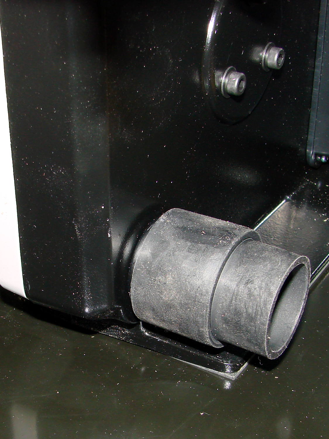
The right-rear mounting screw hides below the dust collection vacuum port:
Micro-Mark Bandsaw – vacuum fitting
You must remove the metal fitting that’s screwed to the frame in the obvious manner:
Micro-Mark Bandsaw – right rear screw – installed
The slowest speed runs a bit faster than I’d like, but I admit to being a sissy.
The 14 tpi blade cuts wood just fine:
Micro-Mark Bandsaw – first cut
The 24 tpi blades should chop up the smaller chunks I generally work with around here.
Bonus: the blade guide just barely clears my huge block of machinable wax.
I bought a 2 inch Micro-Mark Mini Miter / Cut-off Saw to cut screws & brass tubing, in the hopes that it would be somewhat better than the essentially equivalent Harbor Freight offering. I think that’s true, but it’s a near thing.
Apparently, the saws all come from the same factory with the same bass-ackwards vise:
Micro-Mark Cutoff Saw – vise side view
The V-groove should be on the fixed jaw, where it would more-or-less precisely align rods / cylinders with the blade. The moveable jaw isn’t dovetailed to the base of the vise, so it ends up wherever it stops and, somehow, they managed to machine the end of the screw shaft off-center from the shaft, so the moveable jaw moves in a small circle as you tighten it.
A small punch mark locks the jaw to the screw; you can pull the disk on the shaft past the indentation by turning the knob with sufficient enthusiasm:
Micro-Mark Cutoff Saw – clamp jaw detail
The hole in the vise, just under the disk, lets somebody whack the jaw with a punch.
Some machining or an entirely new vise setup lies in the future of this thing.
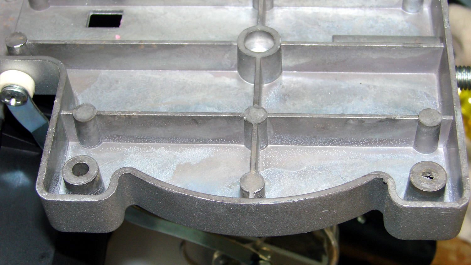
I mounted it on a scrap of countertop by transfer-punching the base holes, only to discover that the punch didn’t leave a mark for one hole, even though a dent was clearly visible at the bottom of the hole with the saw on the countertop.
A bit of headscratching later:
Micro-Mark Cutoff Saw – unfinished casting hole
Apparently the core for that hole in the injection mold didn’t seat quite right. The layer was thin enough to drill out easily.
The mower tried to eat a protruding root, emitted a horrible crash, and ran poorly until I shut it off, after which it refused to restart. Hoping against hope that the flywheel’s aluminum key had sheared, I pulled the cover, removed the starter, and found:
Mower flywheel key
Alas, the key is in fine shape. I made the two diagonal scratches to confirm it really is aluminum.
After letting the mower sit for a day, it started and ran briefly, blatted a giant backfire that probably startled the neighborhood (because I had the exhaust aimed into the garage, which served as a wonderful resonator), died a sudden death, then made clanking sounds whenever I pulled the rope. Something is definitely broken inside, but I suspect diagnosing & fixing it will require more time and money than is justified.
I no longer form deep emotional attachments to lawn mowers, so I ordered a similar one online and the local Sears had it ready for pickup in an hour.
If I had to pull the flywheel, I’d tap the two obvious holes (one behind the shaft in the picture) and gimmick up a puller with two matching screws around a central bolt that does the heavy lifting; I can’t justify the Special Service Tool I’m sure it requires.
The old mower lasted an hour at the foot of the driveway with a “FREE – Engine probably severely broken” sign affixed to its handle; both parties got a great deal on that transaction!
Long ago, Mary picked out a PTT switch with a raised, square post that provided a distinct shape and positive tactile feedback:
PTT Button – bare post
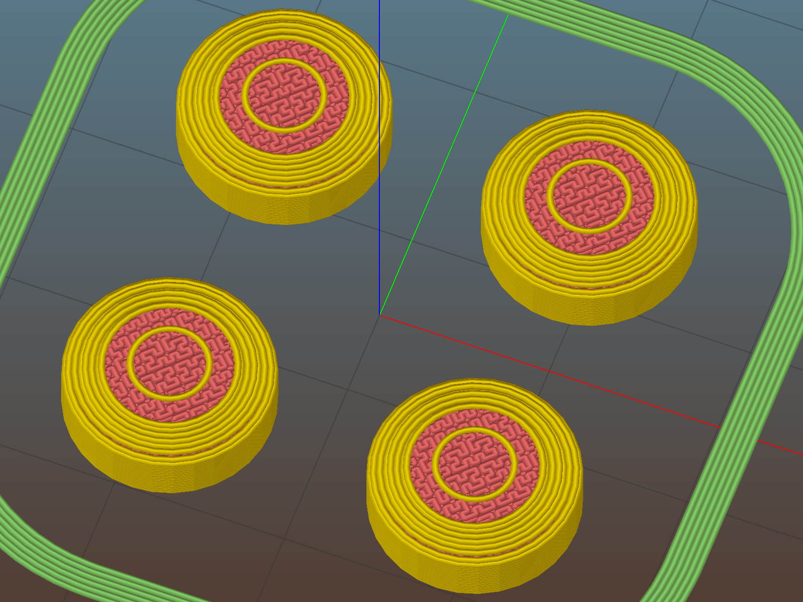
Time passes, she dinged her thumb in the garden, and asked for a more rounded button. I have some switches with rounded caps, but replacing the existing switch looked a lot like work, sooooo:
PTT Button Cap – Slic3r preview
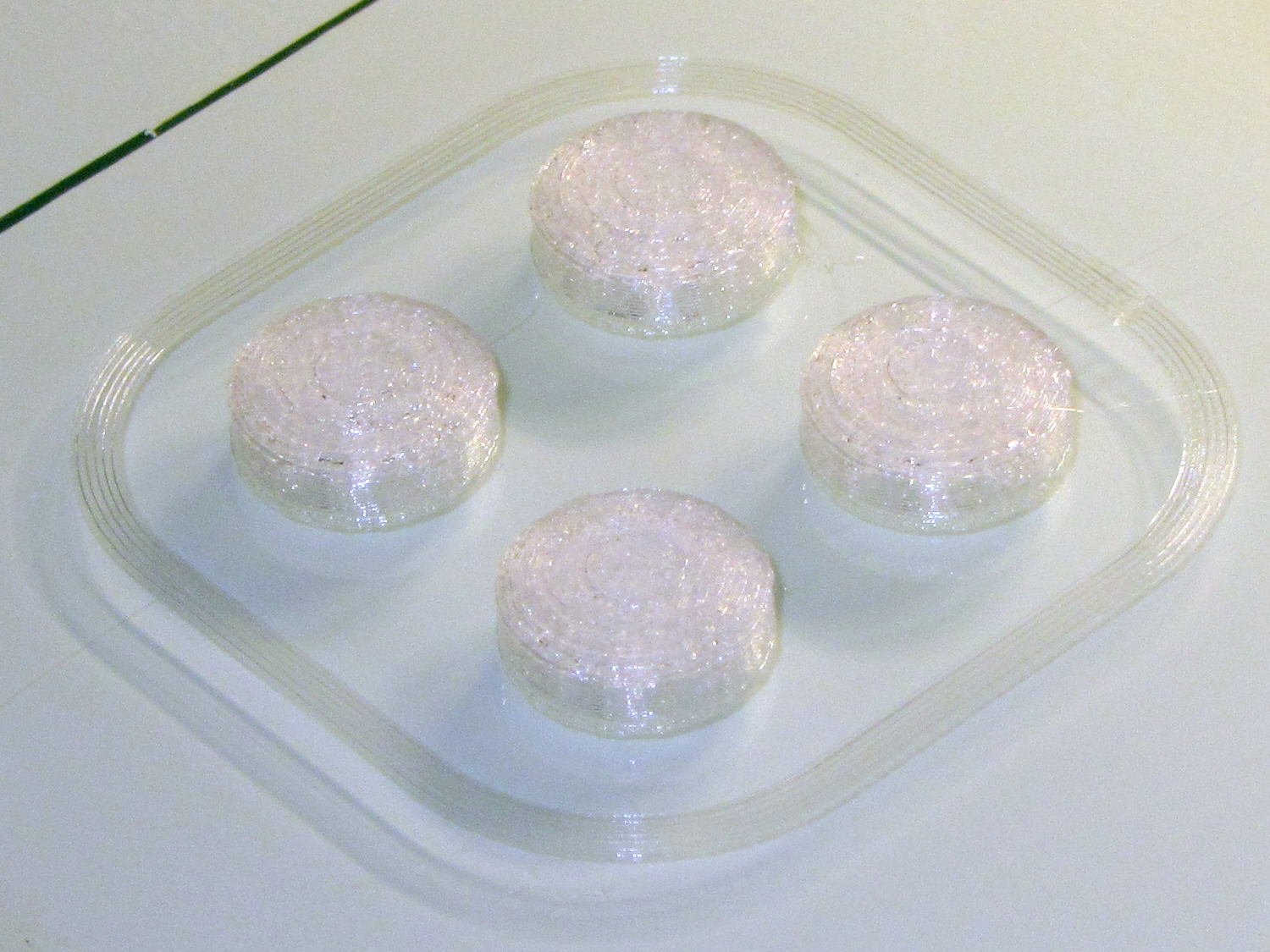
As with all small objects, building them four at a time gives the plastic in each one time to cool before slapping the next layer on top:
PTT Button – on platform
The hole in the cap is 0.2 mm oversize, which results in a snug press fit on the small ridges barely visible around the post in the first image:
PTT Button – rounded cap
Rather than compute the chord covering the surface, I just resized a sphere to twice the desired dome height (picked as 6 threads, just for convenience) and plunked it atop a cylinder. Remember to expand the sphere diameter by 1/cos(180/sides) to make it match the cylinder and force both to have the same number of sides.
This file contains hidden or bidirectional Unicode text that may be interpreted or compiled differently than what appears below. To review, open the file in an editor that reveals hidden Unicode characters.
Learn more about bidirectional Unicode characters
As part of setting the Makergear M2 up after The Great Cleanout, I ran off a set of thinwall calibration squares that showed the left rear corner was high by 0.12 mm: the square in that corner measured 2.88 mm, rather than the intended 3.0 mm. The walls were 0.43 mm, about 10% above the nominal 0.40 mm.
I tightened the rear platform screw by a bit under 1/12 turn, less than half a flat on the hex nut, and dialed the Extrusion Multiplier back by 10%. The next set of squares, set up for walls made of three parallel threads, came out with heights within 0.08 mm of each other and 1.15 mm thick (rather than the nominal 1.20 mm).
They’re 40 mm on a side, mostly to produce bigger handouts for the next show-n-tell:
Thinwall open box – array on platform – 3w 40 3.0
Letting it sit for a few days and running the same G-Code produced heights within 0.07 mm and wall thickness at 1.18, which I defined to be Good Enough.
Recent versions of Slic3r have been adjusting the various thread widths on the fly, as I’ve let everything except the basic extrusion width go with the default values. As a result, setting the wall width to 2 threads (0.80 mm) can produce an extremely thin third thread between the two perimeter threads that doesn’t extrude well. Making the wall three threads wide works much better:
Calibration Box – open – 3w 40 3.0
The slicing algorithms may be smart enough to make all the tricks I’ve learned completely obsolete; that’s fine with me!
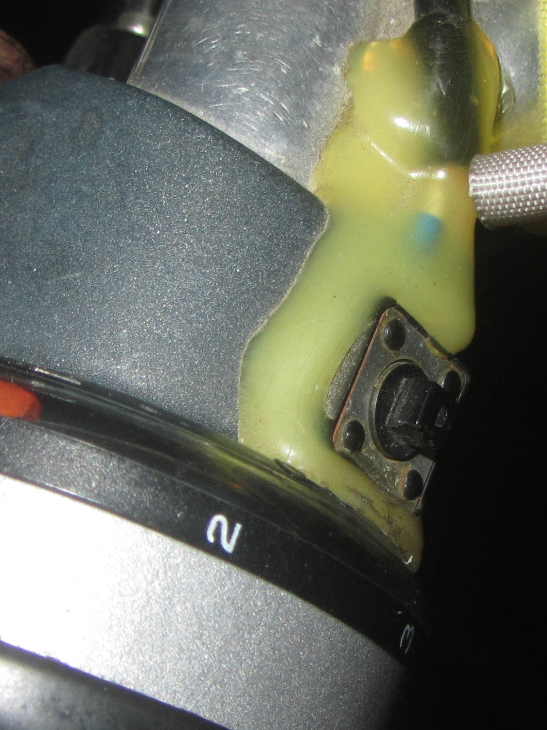
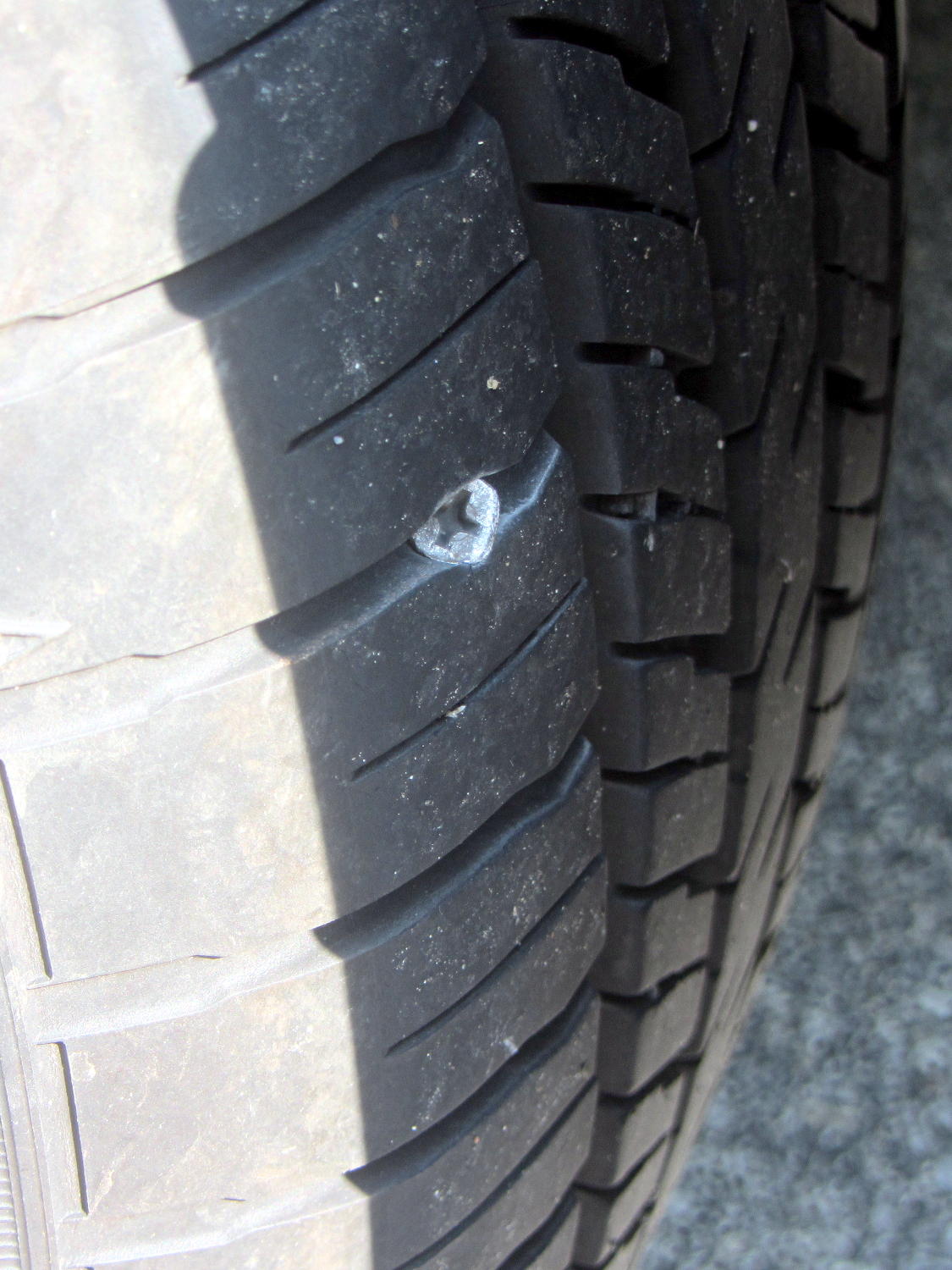
According to the Forester’s manual, the Tire Pressure Monitoring System kicks in after the car reaches 25 mph. It evidently takes a while to figure things out after that, because the TPMS light blinked on a mile from home on the way to Mary’s Vassar Farms garden. I pulled into the next parking lot, measured 20 psi in the left rear tire, then found this staring me in the eye:
Forester – left rear tire with screw
Well, that certainly simplified the diagnosis!
I unloaded two bags of shredded leaves and a pile of hoses, swapped in the (limited use, donut-style) spare tire, and continued the mission.
The TPMS light wasn’t on when I drove to Squidwrench the previous evening. Judging from the wear, that screw appeared during the various errands following our 800 mile road trip, which is good news of a sort, and depressurized the tire over the course of a day or two.
The receipt from the fix-it folks cautions that a plug is a temporary fix, because “the injury has compromised the integrity of the tire”. On the other paw, the Forester manual tells me “All four tires must be the same in terms of manufacturer, brand (tread pattern), construction, and size. You are advised to replace the tires with new ones that are identical to those fitted as standard equipment” and then provides a checklist:
When you replacing or installing tire(s), all four tires must be the same for following items.
(a) Size
(b) Circumference
(c) Speed symbol
(d) Load index
(e) Construction
(f) Manufacturer
(g) Brand (tread pattern)
(h) Degrees of wear
There’s absolutely no way to get an identical replacement tire, let alone one with the same tread wear, but I am so unready to replace all four tires after 12 k miles / 2 years.
After half a dozen years, the bearings in the blender impeller felt pretty bad:
Defunct blender bearings
I wiped everything clean, found the box containing the box containing the tube of bearings, packed the base with more silicone grease, reassembled everything in reverse order, and it’s all good again.
The first repair lasted for a year and the second for six, so I think overpacking the base with grease helped a lot. Maybe I’m getting better at ignoring horrible grinding sounds.
I can do this twice more, although the Jesus clip holding the shaft into the bearing stack definitely needs replacing.