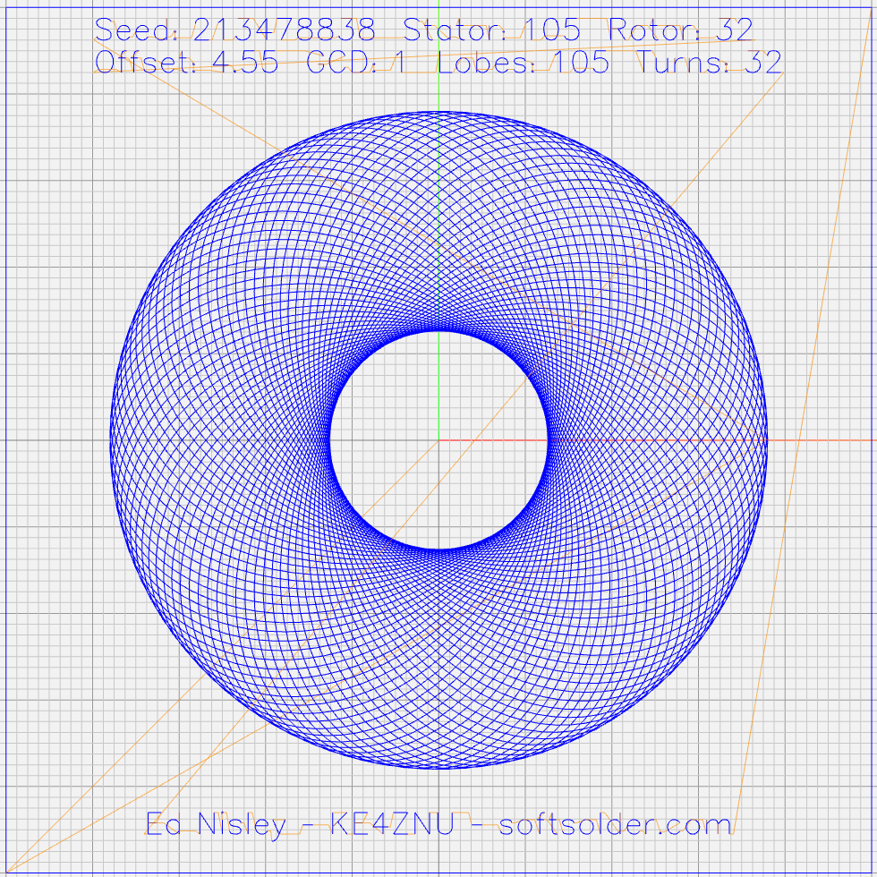
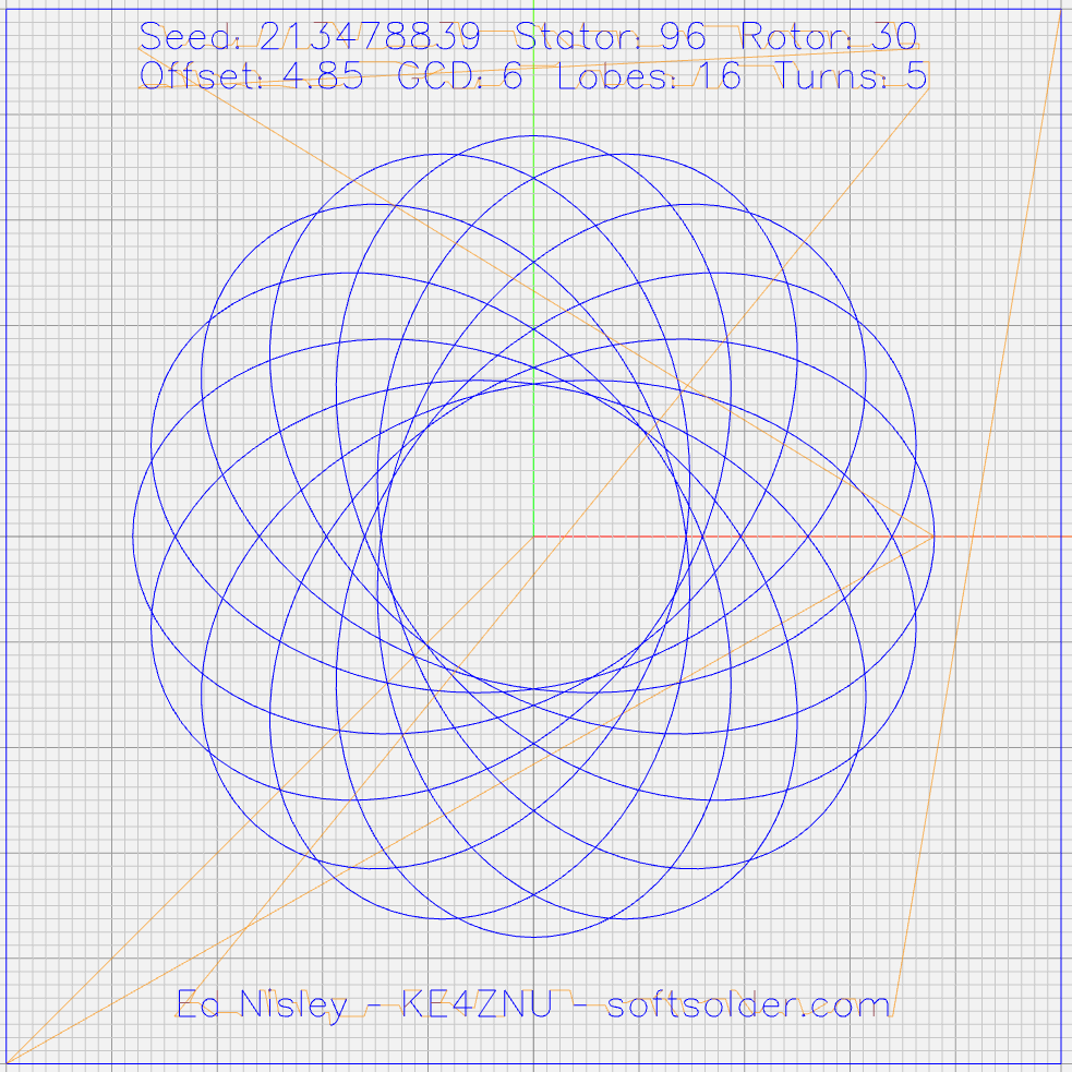
|
// Spirograph simulator for MPCNC used as plotter |
|
// Ed Nisley KE4ZNU – 2017-12-23 |
|
// Adapted for Guillioche plots with ball point pens – 2018-09-25 |
|
|
|
// Spirograph equations: |
|
// https://en.wikipedia.org/wiki/Spirograph |
|
// Loosely based on GCMC cycloids.gcmc demo: |
|
// https://gitlab.com/gcmc/gcmc/tree/master/example/cycloids.gcmc |
|
|
|
// Required command line parameters: |
|
|
|
// -D Pen=n pen selection, 0 = no legend, 1 = current pen |
|
// -D PaperSize=[x,y] overall sheet size: [17in,11in] |
|
// -D PRNG_Seed=i non-zero random number seed |
|
|
|
include("tracepath.inc.gcmc"); |
|
include("engrave.inc.gcmc"); |
|
|
|
//—– |
|
// Greatest Common Divisor |
|
// https://en.wikipedia.org/wiki/Greatest_common_divisor#Using_Euclid's_algorithm |
|
// Inputs = integers without units |
|
|
|
function gcd(a,b) { |
|
if (!isnone(a) || isfloat(a) || !isnone(b) || isfloat(b)) { |
|
warning("GCD params must be dimensionless integers:",a,b); |
|
} |
|
|
|
local d = 0; // power-of-two counter |
|
|
|
while (!((a | b) & 1)) { // remove and tally common factors of two |
|
a >>= 1; |
|
b >>= 1; |
|
d++; |
|
} |
|
|
|
while (a != b) { |
|
if (!(a & 1)) {a >>= 1;} // discard non-common factor of 2 |
|
elif (!(b & 1)) {b >>= 1;} // … likewise |
|
elif (a > b) {a = (a – b) >> 1;} // gcd(a,b) also divides a-b |
|
else {b = (b – a) >> 1;} // … likewise |
|
} |
|
|
|
local GCD = a*(1 << d); // form gcd |
|
|
|
// message("GCD: ",GCD); |
|
return GCD; |
|
|
|
} |
|
|
|
//—– |
|
// Max and min functions |
|
|
|
function max(x,y) { |
|
return (x > y) ? x : y; |
|
} |
|
|
|
function min(x,y) { |
|
return (x < y) ? x : y; |
|
} |
|
|
|
//—– |
|
// Pseudo-random number generator |
|
// Based on xorshift: |
|
// https://en.wikipedia.org/wiki/Xorshift |
|
// http://www.jstatsoft.org/v08/i14/paper |
|
// Requires initial state from calling script |
|
// -D "PRNG_Seed=whatever" |
|
// You can get nine reasonably random digits from $(date +%N) |
|
|
|
function XORshift() { |
|
|
|
local x = PRNG_State; |
|
|
|
x ^= x << 13; |
|
x ^= x >> 17; |
|
x ^= x << 5; |
|
|
|
PRNG_State = x; |
|
return x; |
|
} |
|
|
|
//—– |
|
// Spirograph tooth counts mooched from: |
|
// http://nathanfriend.io/inspirograph/ |
|
// Stators includes both inside and outside counts, because we're not fussy |
|
|
|
Stators = [96, 105, 144, 150]; |
|
Rotors = [24, 30, 32, 36, 40, 45, 48, 50, 52, 56, 60, 63, 64, 72, 75, 80, 84]; |
|
|
|
//—– |
|
// Start drawing things |
|
// Set initial parameters from command line! |
|
|
|
comment("PRNG seed: ",PRNG_Seed); |
|
PRNG_State = PRNG_Seed; |
|
|
|
// Define some useful constants |
|
|
|
AngleStep = 2.0deg; |
|
|
|
Margins = [12mm,12mm] * 2; |
|
|
|
comment("Paper size: ",PaperSize); |
|
|
|
PlotSize = PaperSize – Margins; |
|
comment("PlotSize: ",PlotSize); |
|
|
|
//—– |
|
// Set up gearing |
|
|
|
s = (XORshift() & 0xffff) % count(Stators); |
|
StatorTeeth = Stators[s]; |
|
comment("Stator ",s,": ",StatorTeeth); |
|
|
|
r = (XORshift() & 0xffff) % count(Rotors); |
|
RotorTeeth = Rotors[r]; |
|
comment("Rotor ",r,": ",RotorTeeth); |
|
|
|
GCD = gcd(StatorTeeth,RotorTeeth); // reduce teeth to ratio of least integers |
|
comment("GCD: ",GCD); |
|
StatorN = StatorTeeth / GCD; |
|
RotorM = RotorTeeth / GCD; |
|
|
|
L = to_float((XORshift() & 0x3ff) – 512) / 100.0; // normalized pen offset in rotor |
|
comment("Offset: ", L); |
|
|
|
sgn = sign((XORshift() & 0xff) – 128); |
|
K = sgn*to_float(RotorM) / to_float(StatorN); // normalized rotor dia |
|
comment("Dia ratio: ",K); |
|
|
|
Lobes = StatorN; // having removed all common factors |
|
Turns = RotorM; |
|
|
|
comment("Lobes: ", Lobes); |
|
comment("Turns: ", Turns); |
|
|
|
//—– |
|
// Crank out a list of points in normalized coordinates |
|
|
|
Path = {}; |
|
Xmax = 0.0; |
|
Xmin = 0.0; |
|
Ymax = 0.0; |
|
Ymin = 0.0; |
|
|
|
for (a = 0.0deg ; a <= Turns*360deg ; a += AngleStep) { |
|
x = (1 – K)*cos(a) + L*K*cos(a*(1 – K)/K); |
|
if (x > Xmax) {Xmax = x;} |
|
elif (x < Xmin) {Xmin = x;} |
|
|
|
y = (1 – K)*sin(a) – L*K*sin(a*(1 – K)/K); |
|
if (y > Ymax) {Ymax = y;} |
|
elif (y < Ymin) {Ymin = y;} |
|
|
|
Path += {[x,y]}; |
|
} |
|
|
|
//message("Max X: ", Xmax, " Y: ", Ymax); |
|
//message("Min X: ", Xmin, " Y: ", Ymin); // min will always be negative |
|
|
|
Xmax = max(Xmax,-Xmin); // odd lobes can cause min != max |
|
Ymax = max(Ymax,-Ymin); // … need really truly absolute maximum |
|
|
|
//—– |
|
// Scale points to actual plot size |
|
|
|
PlotScale = [PlotSize.x / (2*Xmax), PlotSize.y / (2*Ymax)]; |
|
comment("Plot scale: ", PlotScale); |
|
|
|
Points = scale(Path,PlotScale); // fill page, origin at center |
|
|
|
//—– |
|
// Start drawing lines |
|
|
|
feedrate(1500.0mm); |
|
|
|
TravelZ = 1.5mm; |
|
PlotZ = -1.0mm; |
|
|
|
//—– |
|
// Box the outline for camera alignment |
|
|
|
goto([-,-,TravelZ]); |
|
goto([-PaperSize.x/2,-PaperSize.y/2,-]); |
|
goto([-,-,PlotZ]); |
|
|
|
foreach ( {[-1,1], [1,1], [1,-1], [-1,-1]} ; pt) { |
|
move([pt.x*PaperSize.x/2,pt.y*PaperSize.y/2,-]); |
|
} |
|
|
|
goto([-,-,TravelZ]); |
|
|
|
//—– |
|
// Draw the plot |
|
|
|
tracepath(Points, PlotZ); |
|
|
|
//—– |
|
// Add legends |
|
// … only for nonzero Pen |
|
|
|
if (Pen) { |
|
feedrate(250mm); |
|
|
|
TextFont = FONT_HSANS_1_RS; |
|
TextSize = [2.5mm,2.5mm]; |
|
TextLeading = 1.5; // line spacing as multiple of nominal text height |
|
|
|
line1 = typeset("Seed: " + PRNG_Seed + " Stator: " + StatorTeeth + " Rotor: " + RotorTeeth,TextFont); |
|
line2 = typeset("Offset: " + L + " GCD: " + GCD + " Lobes: " + Lobes + " Turns: " + Turns,TextFont); |
|
|
|
maxlength = TextSize.x * max(line1[-1].x,line2[-1].x); |
|
|
|
textpath = line1 + (line2 – [-, TextLeading, -]); // undef – n -> undef to preserve coordinates |
|
textorg = [-maxlength/2,PaperSize.y/2 – 0*Margins.y/2 – 2*TextLeading*TextSize.y/2]; |
|
|
|
placepath = scale(textpath,TextSize) + textorg; |
|
comment("Legend begins"); |
|
engrave(placepath,TravelZ,PlotZ); |
|
|
|
attrpath = typeset("Ed Nisley – KE4ZNU – softsolder.com",TextFont); |
|
attrorg = [-(TextSize.x * attrpath[-1].x)/2,-(PaperSize.y/2 – Margins.y/2 + 2*TextLeading*TextSize.y)]; |
|
placepath = scale(attrpath,TextSize) + attrorg; |
|
comment("Attribution begins"); |
|
engrave(placepath,TravelZ,PlotZ); |
|
} |
|
|
|
goto([PaperSize.x/2,PaperSize.y/2,25.0mm]); // done, so get out of the way |