Ed Nisley's Blog: Shop notes, electronics, firmware, machinery, 3D printing, laser cuttery, and curiosities. Contents: 100% human thinking, 0% AI slop.
Two more umbrella struts snapped and required the same repair, but, having drained all the suitable snippets from the Box o’ Brass Cutoffs, some lathe work was in order:
Umbrella strut splint – cutting
I used the carbide insert in the mistaken belief it’d be less grabby, then applied the cutoff tool.
Break the edges, slide splints over the ribs, slobber epoxy on the struts, slide splints into place, apply masking tape for a bit of compression & alignment, and let it cure:
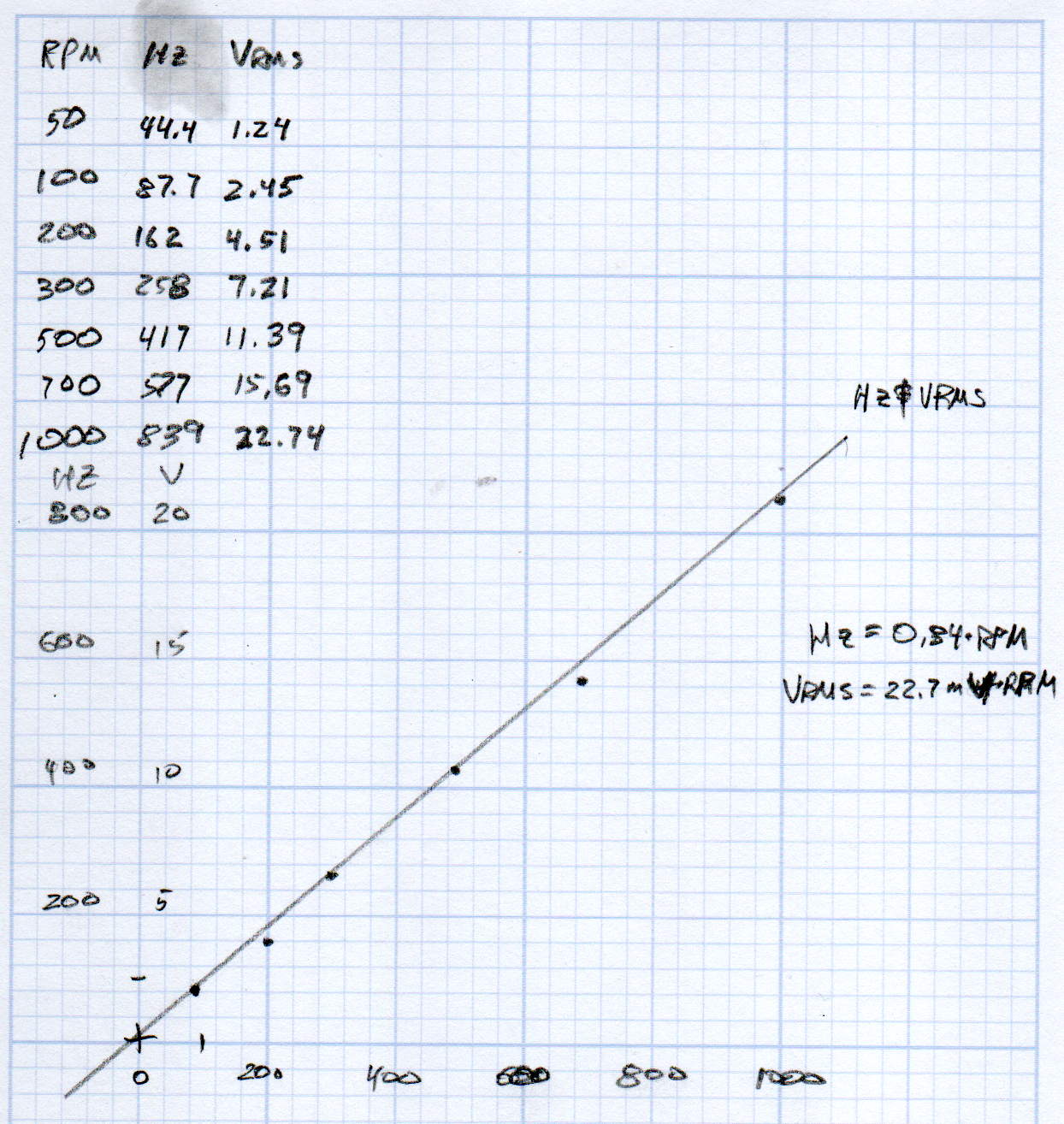
KL17H248-15-4A stepper motor – Back EMF vs RPM – data
Maybe the only questions I ask are ones with linear solutions?
Anyhow, the data comes from the Z-axis motor in the lathe:
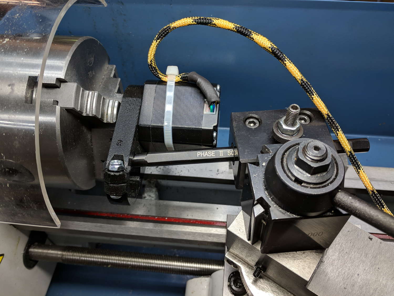
Stepper back EMF test setup
Scary-looking, but reasonably safe. The chuck holds the motor shaft so it’s not going anywhere, the boring bar prevents any rotation, and the motor bearings do exactly what they’re supposed to. Shorting the motor leads would definitely put a hurt on the PLA frame, so I didn’t do that.
The scope sat on the floor beside the lathe, capturing waveforms and doing calculations:
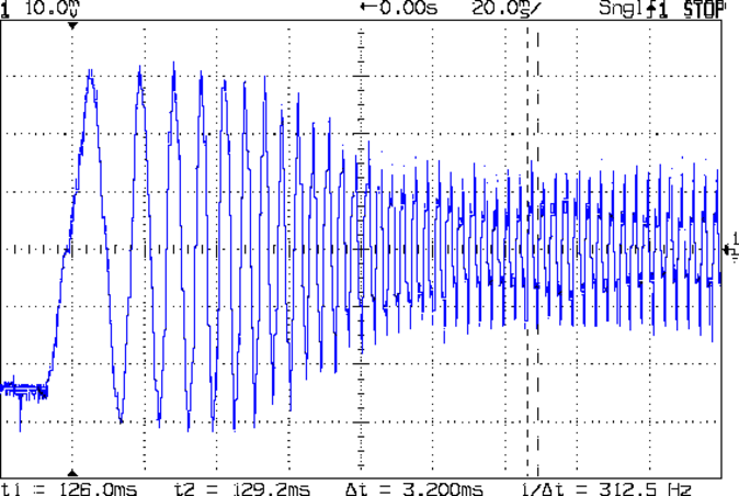
Motor Back EMF – 500 RPM
Some waveforms look bent:
Motor Back EMF – 300 RPM
I asked the scope to measure the RMS voltage, rather than the peak, because it’s less sensitive to distortions.
Each winding produces one electrical cycle across four mechanical full steps, with the windings in quadrature. One shaft revolution thus produces 200 / 4 = 50 electrical cycles, so converting from shaft RPM into electrical cycles/s goes a little something like this:
So the shaft turns at 375 RPM when the X axis moves at 12 k mm/min, with each motor generating 8.5 Vrms = 12 Vpk of back EMF.
The MPCNC wires the two motors on each axis in series, so the 24 V power supply faces 24 V of back EMF (!) from both motors, leaving exactly nothing to push the winding current around. Because the highest EMF occurs at the zero crossing points of the (normal) winding current, I think the current peaks now occur there, with the driver completely unable to properly shape the current waveform.
What you see in the scope shot is what actually happens: the current stabilizes at a ragged square-ish wave at maybe 300 mA (plus those nasty spikes). More study is needed.
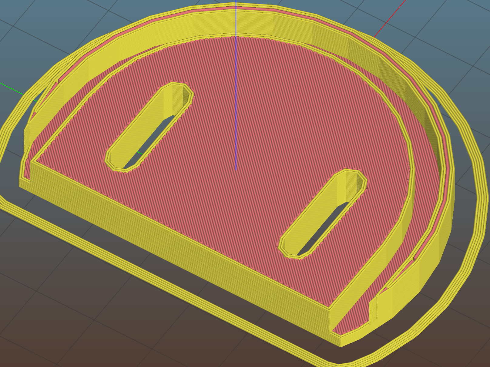
We just scrapped out the old dish drainer, only to find the gadget bin on the new drainer let the measuring spoons fall over and lie along its bottom. After a week of fishing them out from under paring knives, cheese slicers, and suchlike, I gimmicked up a holder:
Measuring Spoon Drainer – installed
One might suggest natural PETG, rather than orange, thereby displaying a shocking ignorance of the MVP concept. We’ll run with orange for the shakedown trials, then build-measure-learn, iterate, and, for all I know, we may even pivot.
A bottom-up view of the solid model shows the trench accommodating the bin lip:
This file contains hidden or bidirectional Unicode text that may be interpreted or compiled differently than what appears below. To review, open the file in an editor that reveals hidden Unicode characters.
Learn more about bidirectional Unicode characters
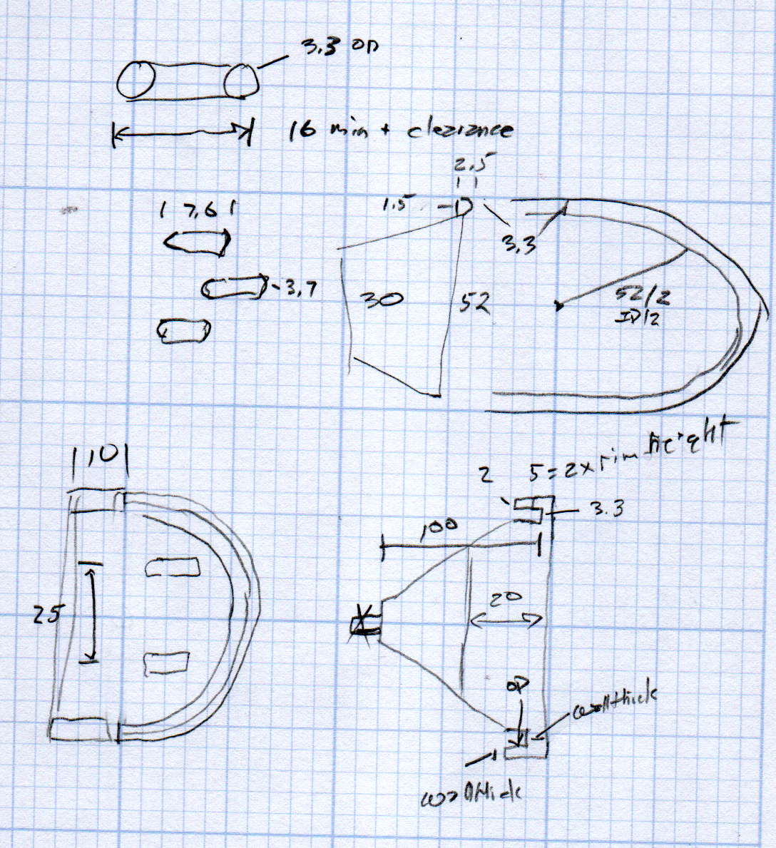
The MPCNC uses a DW660 Cutout tool as a low-cost spindle for tools with 1/8 and 1/4 inch shanks. It features a tool-free “collet grip” to twist the collet nut against the shaft lock, which is convenient for a hand tool and not so much for a CNC spindle: I find it difficult to get two hands into the MPCNC setup with the proper orientation to push-and-hold two locking buttons, while applying enough torque to twist the collet nut:
DW660 – collet grip
Fortunately, it’s easy enough to remove the collet grip. Remove the collet nut, unscrew the four screws holding the yellow snout in place, then pull the snout straight off to reveal the spindle lock plate:
DW660 – nose cap interior
Capture the spring, slide the spindle lock plate out to expose the snap ring (a.k.a. Jesus clip) holding the collet grip in place:
DW660 – collet grip snap ring
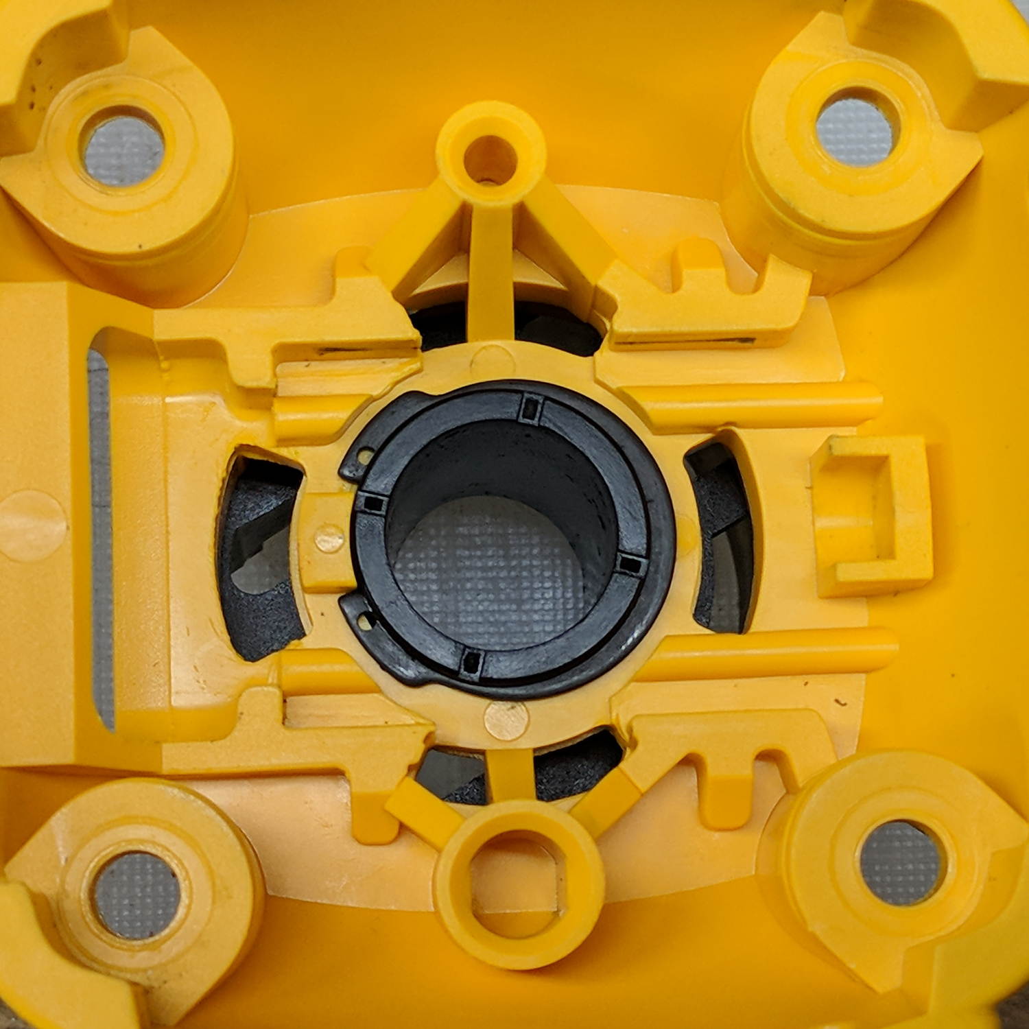
Remove the snap ring, make the appropriate remark, pull the collet grip out of the snout, reassemble the snout in its One Correct Orientation, and you’re done:
DW660 – collet grip removed
The retroreflective tape snippet let my laser tachometer report a top speed over 29 k rpm, pretty close to the advertised 30 k rpm.
If one were fussy, one would 3D print a thing to cover the snout’s open end:
DW660 – snout cover
The original snap ring holds it in place and the fancy pattern comes from octogram spiral infill on the bottom.
The collet nut fits either a 5/8 inch or 16 mm wrench, both of which stick out to the side far enough for a convenient hold while pressing the shaft lock button.
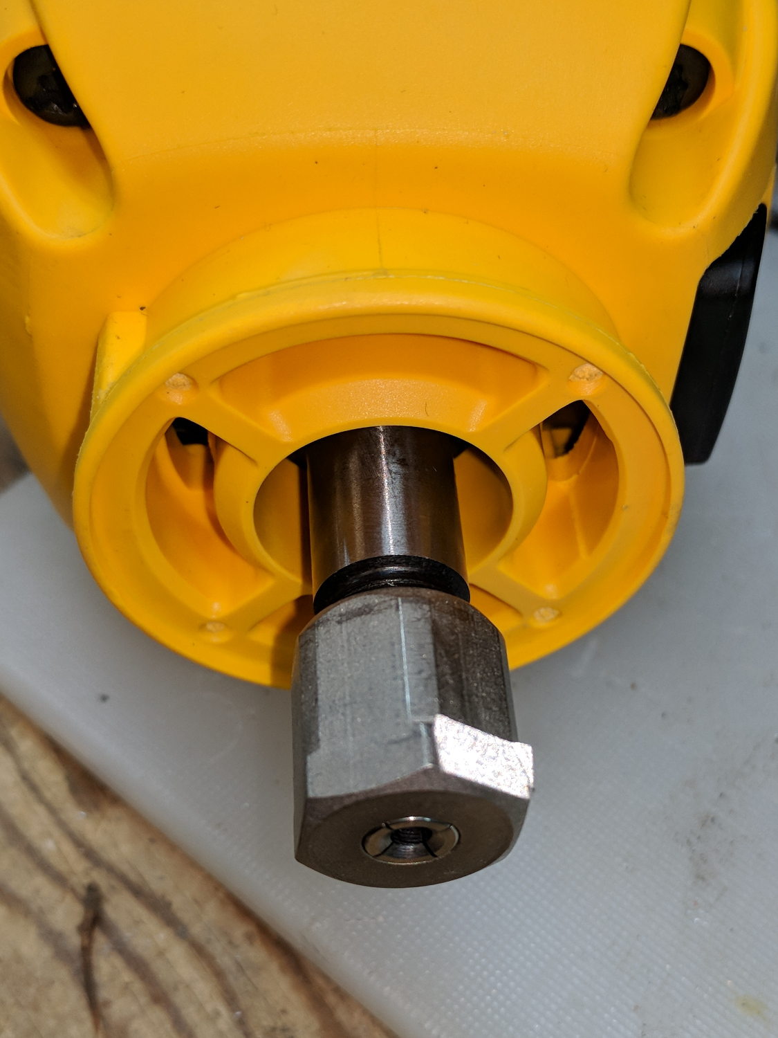
The idea behind this gadget surfaced while I was looking for something else and, although the front panel makes my skin crawl, it’s just an adjustable DC power supply:
Let’s say it has the potential to be a DC power supply, although we might quibble about the “Precision” part.
As delivered, it’s a deathtrap. Of course, it’s not UL listed and I didn’t expect it to be.
How many lethal problems do you see?
Tattoo power supply – original AC wiring
For starters, it has a three-wire AC line cord with the green-and-yellow conductor chopped off flush with the outer insulation inside the heatshrink tubing just behind the transformer:
Tattoo power supply – ungrounded AC line
The blue wire is AC neutral, but it really shouldn’t be connected to the finger-reachable outer fuse terminal.
The brown wire is AC line, which goes directly to one power switch terminal. In the event of a hot wiring fault, an unfused conductor touching the case will test the GFI you should have on your bench wiring.
The AC line cord uses some mysterious copper-colored metallic substance that’s about as stiff as music wire:
Tattoo power supply – stiff AC wire
The strands cannot be twisted together like ordinary copper wire, although they can be soldered. They may be copper-plated aluminum, because a magnet ignores them.
After soldering the strands together, they snap when bent:
Tattoo power supply – soldered broken AC wire
Generous strain relief is not just a good idea, it’s mandatory.
After some Quality Shop Time, the ground wire now connects to the case through the transformer’s rear mounting screw, the neutral AC wire connects to the transformer, the hot AC wire goes to the tip of the line fuse, and the fuse cap terminal goes to the switch:
Tattoo power supply – AC line rewiring
I relocated the white LED to the middle of the meter, where it looks a bit less weird:
Tattoo power supply – revised front panel
I have no idea what “Porket indicate” might mean. Perhaps “Precision indicator”?
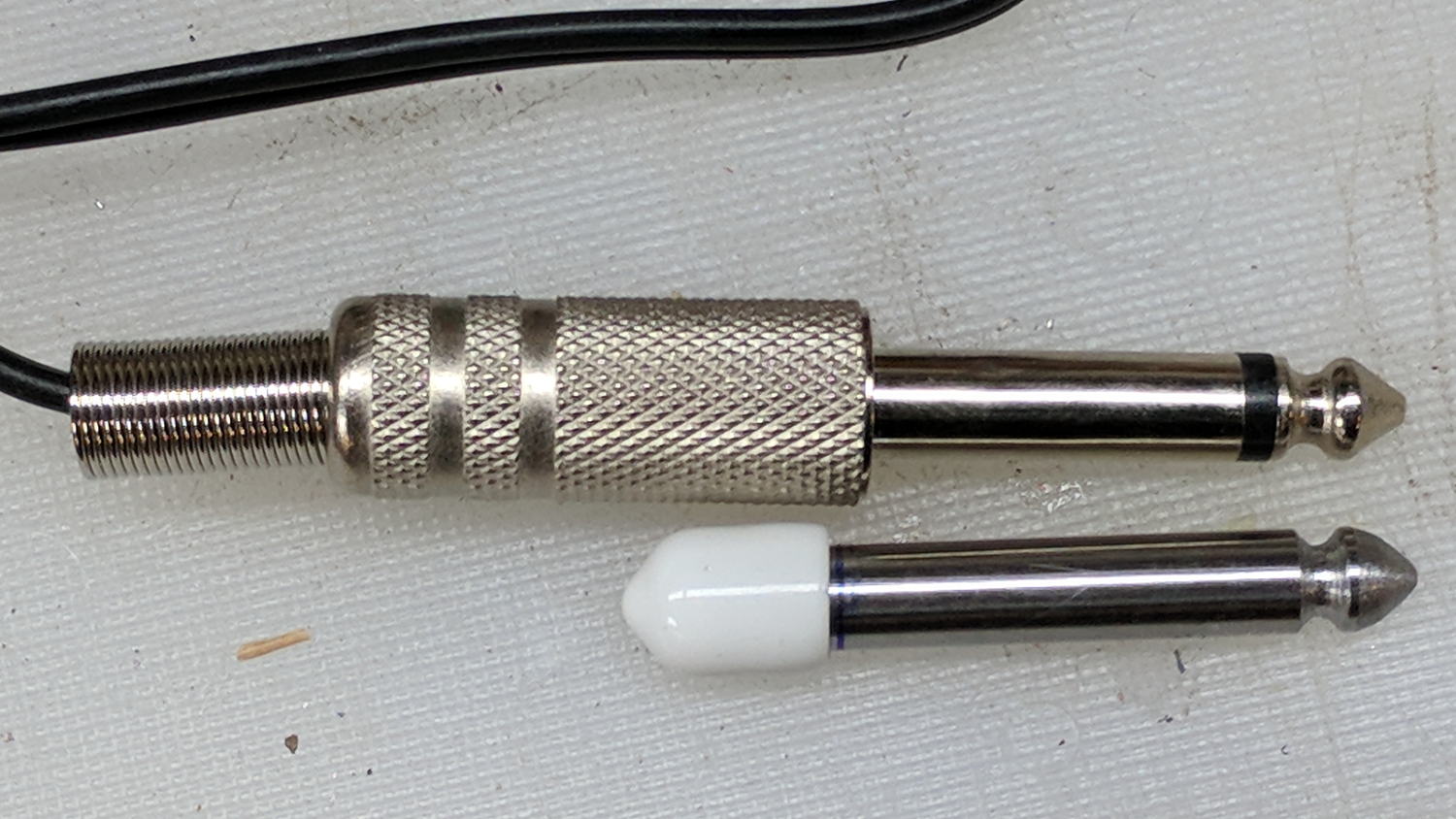
The right 1/4 inch jack, labeled “Foot”, normally goes to a foot switch you don’t need for a bench power supply, so I converted a length of drill rod into a dummy plug to short the jack contacts:
Tattoo power supply – dummy switch plug
The tip comes from a bit of lathe and file work and the white cap comes from a bag of wire shelf hardware.
A genuine hologram sticker (!) on the back panel proclaims “1.5 – 15 VDC 2 A”, which seemed optimistic. Some fiddling with power resistors suggests tattoo liners (I learned a new word!) don’t draw much current:
4 V @ 1 A
8 V @ 800 mA
10 V @ 600 mA
It can reach a bit over 18 V (pegging the meter) at lower current, so it’s Good Enough for small projects with un-fussy power requirements.
When I wired up the MPCNC’s tool length probe, I planned to reinforce the wiring with a dab of epoxy. What I didn’t notice in my enthusiasm, alas, was the opening from the rear to the front in each pin slot:
Epoxied connector – rear
Which let the epoxy flow completely through the connector:
Epoxied connector – front
So I cut the mess off and applied heatstink tubing on each wire, just like I should have in the first place.
Now you know the rest of the story …
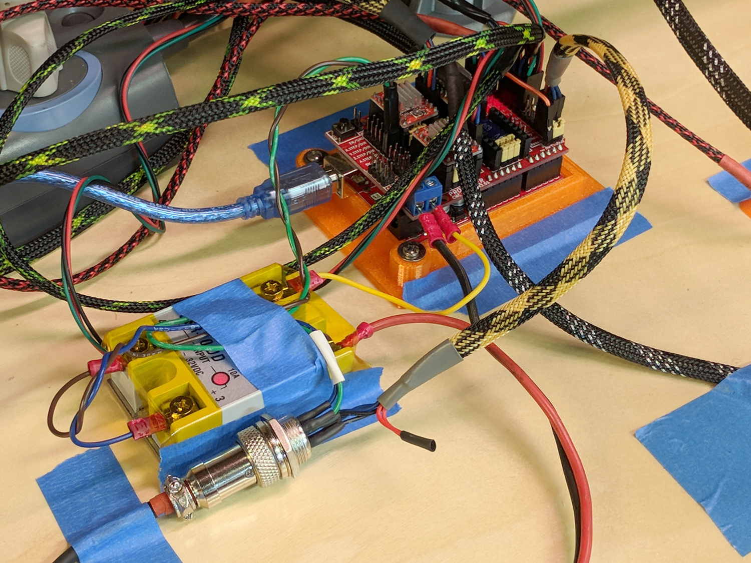
I really dislike pin headers as cable connectors, but that’s what the Protoneer CNC board uses:
MPCNC – Protoneer Wiring – SSR
It’ll be Good Enough if I don’t do anything else particularly stupid.
Although I repaired the spout a while ago, those water bottles were never satisfactory and saw very little use. A recent cabinet cleanout showed the “stainless steel” has passed beyond its best-used-by date:
Stainless steel water bottle – rust
With no regard for whether the patient would survive the operation, I peeled off its rubber foot and applied the Lesser Hammer:
Stainless steel water bottle – insulation
The “insulation” seems to be a rigid urethane-like foam disk few millimeters thick on the bottom of the interior flask, with good old air around the sides.
The bottles never worked very well and now we know why.