The Smell of Molten Projects in the Morning

Ed Nisley's Blog: Shop notes, electronics, firmware, machinery, 3D printing, laser cuttery, and curiosities. Contents: 100% human thinking, 0% AI slop.

Category: Machine Shop

Mechanical widgetry

  • Bathroom Sink Drain: Epoxy FAIL

    Apparently, “porcelain chip fix” epoxy survives about a year in a bathroom sink:

    Bathroom sink epoxy - top
    Bathroom sink epoxy – top

    It came loose from the drain rim while I was cleaning the sink; I wasn’t doing anything particularly vigorous.

    The stain in the lower right goes all the way around the epoxy:

    Bathroom sink epoxy - bottom
    Bathroom sink epoxy – bottom

    For what should be obvious reasons, I was loathe to scuff up the sink surface to give the epoxy a better grip, so it couldn’t make a watertight seal all the way around.

    A closer look at the stain:

    Bathroom sink epoxy - detail
    Bathroom sink epoxy – detail

    I’m reasonably sure that’s iron bacteria colony, rather than actual rust, as there’s no iron to be found anywhere nearby.

    For lack of anything smarter, I’ll apply another dose of the same epoxy, although this time I won’t be expecting a long-term fix.

  • CNC 3018-Pro: HD and CD Fixtures

    I actually had this in mind when I laid out the hard drive and CD engraving fixtures:

    CNC 3018-Pro - HD and CD fixtures
    CNC 3018-Pro – HD and CD fixtures

    The fixtures are centered at X±70.0 mm / Y=0.0 from the G54 workspace coordinate origin dead-center in the middle of the platform, with G55 centered on the HD fixture to the left and G56 on the CD fixture to the right.

    So the engraving workflow amounts to homing the CNC 3018 when I turn it on, taping a platter in a fixture, selecting the corresponding WCS, loading a suitable G-Code file, and firing it off. It seems bCNC returns to G54 after completing the file, so verifying the WCS selection every time is Very Good Practice.

    The friable lacquer coating on some CDs fills my world with glitter whenever I engrave a pattern on their label side. I didn’t plan on a dust shoe for this thing!

  • Makergear M2: Octopi Camera Mount

    Octopirint / Octopi works wonderfully well as a controller / G-Code feeder for my Makergear M2. After putting up with an ungainly mass of tape for far too long, I printed Toddman’s Pi Camera Mount:

    Pi Camera - M2 Mount - Slic3r
    Pi Camera – M2 Mount – Slic3r

    Which snapped together exactly like it should:

    Makergear M2 - Pi Camera Mount
    Makergear M2 – Pi Camera Mount

    A strip of double-sided foam tape attaches it to the Pi’s case, which is Velcro-ed to the M2’s frame. The cable may be too long, but avoids sharp bends on the way out of the case.

    The whole lashup works fine:

    Pi Camera - M2 Mount - Octopi timelapse
    Pi Camera – M2 Mount – Octopi timelapse

    That’s a second set intended for the CNC 3018-Pro, but it didn’t fit quite as well. The B brackets are slightly too long (or their pivots are slightly too close to their base) to allow the C plates to turn 90° to the mount:

    Pi Camera - M2 Mount - Config 2 diagram
    Pi Camera – M2 Mount – Config 2 diagram

    Nothing one can’t fix with nibbling & filing, but I long for parametric designs …

  • GCMC Platter Engraving

    Engraving Spirograph / Guilloché patterns on scrap CDs and hard drive platters now works better than ever:

    Spirograph - 674203941 - preview
    Spirograph – 674203941 – preview

    After, that is, I realized:

    • Any Rotor will work, as long as it’s smaller than the Stator
    • You must pick pen offset L so the pattern never crosses the stator center point
    • L ≥ 1 is perfectly fine
    • You must scale the resulting pattern to fit the actual space on the disk

    One of my final doodles showing how the variables relate to each other, although the Wikipedia article may be useful for the underlying math and other posts have more pix on various machines:

    Spirograph Scaling doodles
    Spirograph Scaling doodles

    Cheat sheet:

    • Stator has tooth count (∝ radius) R
    • Rotor has tooth count (∝ radius) r
    • K = r/R, so if you normalize R=1, K=r
    • Pen offset L puts it at radius rL in the rotor

    Picking a suitable rotor requires iterating with random choices until one fits:

      RotorTeeth = Stators[-1];
      n = 0;
      while (RotorTeeth >= floor(0.95 * StatorTeeth) || RotorTeeth < 5) {
        RotorTeeth = (XORshift() & 0x007f);       // this is why Stator can't have more than 127 teeth
        n++;
      }
      comment("Rotor: ",RotorTeeth," in ",n," iterations");

    The 5% buffer on the high end ensures there will be an L keeping a hole in the middle of the pattern. Requiring at least five teeth on the low end just seems like a Good Idea.

    Given the stator & rotor tooth counts, iterate on random L values until one works:

      n = 0;
      do {
        L = (to_float((XORshift() & 0x1f) + 1) / 32.0) * (1.0/K - 1.0);   // allow L > 1.0
        n++;
      } while (L >= (1.0/K - 1.0) || L < 0.01);
    }
    comment("Offset L: ", L," in ",n," iterations");

    With L chosen to leave a hole in the middle of the pattern, then the pattern traced by the pen in the rotor is centered at 1.0 – K (the normalized Stator radius minus the normalized Rotor radius) and varies by ±LK (the offset times the normalized Rotor radius) on either side:

    RotorMin = 1.0 - 2*K;
    comment("Rotor Min: ",RotorMin);
    
    BandCtr = 1.0 - K;                      // band center radius
    BandMin = BandCtr - L*K;                //  ... min radius
    BandMax = BandCtr + L*K;                //  ... max radius
    
    BandAmpl = BandMax - BandCtr;
    
    comment("Band Min: ",BandMin," Ctr: ",BandCtr," Max: ",BandMax);

    Knowing that, rescaling the pattern to fit the disk limits goes like this:

    FillPath = {};
    
    foreach (Path; pt) {
    
      a = atan_xy(pt);                      // recover angle to point
      r = length(pt);                       //  ... radius to point
    
      br = (r - BandCtr) / BandAmpl;        // remove center bias, rescale to 1.0 amplitude
      dr = br * (OuterRad - MidRad);        // rescale to fill disk
      pr = dr + MidRad;                     // set at disk centerline
    
      x = pr * cos(a);                      // find new XY coords
      y = pr * sin(a);
    
      FillPath += {[x,y]};
    }
    
    comment("Path has ",count(FillPath)," points");

    The final step prunes coordinates so close together as to produce no useful motion, which I define to be 0.2 mm:

    PointList = {FillPath[0]};                // must include first point
    
    lp = FillPath[0];
    n = 0;
    
    foreach (FillPath; pt) {
      if (length(pt - lp) <= Snuggly) {       // discard too-snuggly point
        n++;
      }
      else {
        PointList += {pt};                    // otherwise, add it to output
        lp = pt;
      }
    }
    
    PointList += {FillPath[-1]};                // ensure closure at last point
    
    comment("Pruned ",n," points, ",count(PointList)," remaining");

    The top of the resulting G-Code file contains all the various settings for debugging:

    (Disk type: CD)
    (Outer Diameter: 117.000mm)
    (        Radius: 58.500mm)
    (Inner Diameter: 38.000mm)
    (        Radius: 19.000mm)
    (Mid Diameter: 77.500mm)
    (      Radius: 38.750mm)
    (Legend Diameter: 30.000mm)
    (         Radius: 15.000mm)
    (PRNG seed: 674203941)
    (Stator 8: 71)
    (Rotor: 12 in 1 iterations)
    (Dia ratio K: 0.169 1/K: 5.917)
    (GCD: 1)
    (Lobes: 71)
    (Turns: 12)
    (Offset L: 3.227 in 1 iterations)
    (Rotor Min: 0.662)
    (Band Min: 0.286 Ctr: 0.831 Max: 1.376)
    (Path has 43201 points)
    (Pruned 14235 points, 28968 remaining)

    The GCMC source code as a GitHub Gist:

    // Spirograph simulator for MPCNC used as plotter
    // Ed Nisley KE4ZNU – 2017-12-23
    // Adapted for Guillioche plots with ball point pens – 2018-09-25
    // 2019-06 Text on circular arcs
    // 2019-08 Coordinate pruning
    // 2019-09 Allow L > 1.0, proper scale to fit disk
    // Spirograph equations:
    // https://en.wikipedia.org/wiki/Spirograph
    // Loosely based on GCMC cycloids.gcmc demo:
    // https://gitlab.com/gcmc/gcmc/tree/master/example/cycloids.gcmc
    //—–
    // Library routines
    include("tracepath.inc.gcmc");
    include("engrave.inc.gcmc");
    //—–
    // Define useful constants
    SafeZ = 10.00mm;
    TravelZ = 1.00mm;
    AngleStep = 0.1deg;
    Snuggly = 0.2mm; // prune coordinates when closer
    TextFont = FONT_HSANS_1_RS;
    TextSize = [1.5mm,1.5mm];
    //—–
    // Command line parameters
    // -D DiskType="string"
    if (!isdefined("DiskType")) {
    DiskType = "CD";
    }
    if (DiskType != "CD" && // list all possible types
    DiskType != "3.5" &&
    DiskType != "TrimCD"
    ) {
    error("Unknown disk type: ",DiskType);
    }
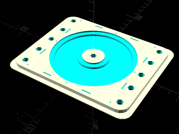
    comment("Disk type: ",DiskType); // default is "CD"
    Margin = 1.5mm; // clamping margin around disk OD
    DiskDia = (DiskType == "3.5") ? 95.0mm :
    (DiskType == "TrimCD") ? 95.0mm :
    120.0mm;
    OuterDia = DiskDia – 2*Margin;
    OuterRad = OuterDia / 2;
    comment("Outer Diameter: ",OuterDia);
    comment(" Radius: ",OuterRad);
    InnerDia = (DiskType == "3.5") ? 33.0mm :
    (DiskType == "TrimCD") ? 38.0mm :
    38.0mm;
    InnerDia = InnerDia;
    InnerRad = InnerDia / 2;
    comment("Inner Diameter: ",InnerDia);
    comment(" Radius: ",InnerRad);
    MidDia = (InnerDia + OuterDia) / 2;
    MidRad = MidDia / 2;
    comment("Mid Diameter: ",MidDia);
    comment(" Radius: ",MidRad);
    LegendDia = (DiskType == "3.5") ? 31.0mm :
    (DiskType == "TrimCD") ? 31.0mm :
    30.0mm;
    LegendDia = LegendDia;
    LegenRad = LegendDia / 2;
    comment("Legend Diameter: ",LegendDia);
    comment(" Radius: ",LegenRad);
    // -D PRNG_Seed=integer non-zero random number seed
    if (isdefined("PRNG_Seed")) { // did we get a seed?
    if (!PRNG_Seed) { // .. it must not be zero
    PRNG_Seed = 347221084;
    }
    }
    else { // no incoming seed, so use a constant
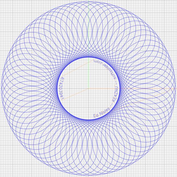
    PRNG_Seed = 674203941;
    }
    comment("PRNG seed: ",PRNG_Seed);
    PRNG_State = PRNG_Seed; // set initial state
    // -D various other useful tidbits
    // add unit to speeds and depths: 2000mm / -3.00mm / etc
    if (!isdefined("PlotSpeed")) {
    PlotSpeed = 2400mm;
    }
    if (!isdefined("TextSpeed")) {
    TextSpeed = 2000mm;
    }
    // Force is proportional to depth, but you must know the coefficent!
    if (!isdefined("PlotZ")) {
    PlotZ = (DiskType == "3.5") ? -3.00 : -0.25mm;
    }
    if (!isdefined("Legend")) {
    Legend = "Ed Nisley – KE4ZNU – softsolder.com";
    }
    //—–
    // Spirograph tooth counts mooched from:
    // http://nathanfriend.io/inspirograph/
    // Stators includes both inside and outside counts, because we're not fussy
    // Stator with prime tooth count will always produce that number of lobes
    // Prime numbers:
    // https://en.wikipedia.org/wiki/Prime_number
    // Table of primes:
    // https://www.factmonster.com/math/numbers/prime-numbers-facts-examples-table-all-1000
    // Must be sorted and should not exceed 127 teeth, which will make plenty of lobes
    Stators = [37,41,43,47,53,59,61,67,71,73,79,83,89,97,101,103,107,109,113,127];
    // Rotor tooth count chosen randomly, these are for the old method
    Rotors = [24, 30, 32, 36, 40, 45, 48, 50, 52, 56, 60, 63, 64, 72, 75, 80, 84];
    //Rotors = [5,7,11,13,17,19,23,31,37,41,47];
    //—–
    // Greatest Common Divisor
    // https://en.wikipedia.org/wiki/Greatest_common_divisor#Using_Euclid's_algorithm
    // Inputs = integers without units
    // This is unused with prime rotor tooth counts left here for completeness
    function gcd(a,b) {
    if (!isnone(a) || isfloat(a) || !isnone(b) || isfloat(b)) {
    error("GCD params must be dimensionless integers. a: ",a," b: ",b);
    }
    local d = 0; // power-of-two counter
    while (!((a | b) & 1)) { // remove and tally common factors of two
    a >>= 1;
    b >>= 1;
    d++;
    }
    while (a != b) {
    if (!(a & 1)) {a >>= 1;} // discard non-common factor of 2
    elif (!(b & 1)) {b >>= 1;} // … likewise
    elif (a > b) {a = (a – b) >> 1;} // gcd(a,b) also divides a-b
    else {b = (b – a) >> 1;} // … likewise
    }
    local GCD = a*(1 << d); // form gcd
    // message("GCD: ",GCD);
    return GCD;
    }
    //—–
    // Max and min functions
    function max(x,y) {
    return (x > y) ? x : y;
    }
    function min(x,y) {
    return (x < y) ? x : y;
    }
    //—–
    // Pseudo-random number generator
    // Based on xorshift:
    // https://en.wikipedia.org/wiki/Xorshift
    // http://www.jstatsoft.org/v08/i14/paper
    // Requires initial state from calling script
    // -D "PRNG_Seed=whatever"
    // Bash (et. al.) supplies nine reasonably random digits from $(date +%N)
    function XORshift() {
    local x = PRNG_State; // fetch current state
    x ^= x << 13;
    x ^= x >> 17;
    x ^= x << 5;
    PRNG_State = x; // save state for next invocation
    return x;
    }
    //—–
    // Bend text around an arc
    function ArcText(TextPath,Center,Radius,BaseAngle,Align) {
    PathLength = TextPath[-1].x;
    Circumf = 2*pi()*Radius;
    TextAngle = to_deg(360 * PathLength / Circumf);
    AlignAngle = BaseAngle + (Align == "Left" ? 0 :
    Align == "Center" ? -TextAngle / 2 :
    Align == "Right" ? -TextAngle :
    0);
    ArcPath = {};
    foreach(TextPath; pt) {
    if (!isundef(pt.x) && !isundef(pt.y) && isundef(pt.z)) { // XY motion, no Z
    r = Radius – pt.y;
    a = 360deg * (pt.x / Circumf) + AlignAngle;
    ArcPath += {[r*cos(a) + Center.x, r*sin(a) + Center.y,-]};
    }
    elif (isundef(pt.x) && isundef(pt.y) && !isundef(pt.z)) { // no XY, Z up/down
    ArcPath += {pt};
    }
    else {
    error("Point is not pure XY or pure Z: " + to_string(pt));
    }
    }
    return ArcPath;
    }
    //—–
    // Set up gearing
    s = (XORshift() & 0xffff) % count(Stators);
    StatorTeeth = Stators[s];
    comment("Stator ",s,": ",StatorTeeth);
    // When Stator has prime teeth, any Rotor will have GCD = 1
    if (1) {
    RotorTeeth = Stators[-1];
    n = 0;
    while (RotorTeeth >= floor(0.95 * StatorTeeth) || RotorTeeth < 5) {
    RotorTeeth = (XORshift() & 0x007f); // this is why Stator can't have more than 127 teeth
    n++;
    }
    comment("Rotor: ",RotorTeeth," in ",n," iterations");
    }
    else {
    r = (XORshift() & 0xffff) % count(Rotors);
    RotorTeeth = Rotors[r];
    comment("Rotor ",r,": ",RotorTeeth);
    }
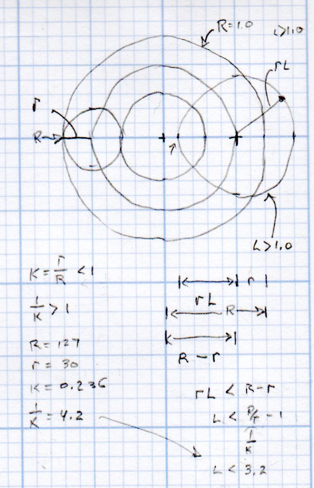
    K = to_float(RotorTeeth) / to_float(StatorTeeth); // find normalized rotor dia
    comment("Dia ratio K: ",K," 1/K: ",1.0/K);
    GCD = gcd(StatorTeeth,RotorTeeth); // reduce teeth to ratio of least integers
    comment("GCD: ",GCD);
    Lobes = StatorTeeth / GCD; // compute useful values
    comment("Lobes: ", Lobes);
    Turns = RotorTeeth / GCD;
    comment("Turns: ", Turns);
    // Find normalized pen offset to never cross Stator center
    if (1) {
    n = 0;
    do {
    L = (to_float((XORshift() & 0x1f) + 1) / 32.0) * (1.0/K – 1.0); // allow L > 1.0
    // comment(" test L: ",L);
    n++;
    } while (L >= (1.0/K – 1.0) || L < 0.01);
    }
    else {
    n = 0;
    do {
    L = to_float((XORshift() & 0x1f) + 1) / 32.0; // force L < 1.0
    n++;
    } while (L >= (1.0/K – 1.0) || L < 0.01);
    }
    comment("Offset L: ", L," in ",n," iterations");
    //—–
    // Crank out a list of points in normalized coordinates
    Path = {};
    for (a = 0.0deg ; a <= Turns*360deg ; a += AngleStep) {
    x = (1 – K)*cos(a) + L*K*cos(a*(1 – K)/K);
    y = (1 – K)*sin(a) – L*K*sin(a*(1 – K)/K);
    Path += {[x,y]};
    }
    //—–
    // Calculate normalized limits for band traced by pen in rotor at offset L
    // L was chosen to produce a band around the rotor center point
    RotorMin = 1.0 – 2*K;
    comment("Rotor Min: ",RotorMin);
    BandCtr = 1.0 – K; // band center radius
    BandMin = BandCtr – L*K; // … min radius
    BandMax = BandCtr + L*K; // … max radius
    BandAmpl = BandMax – BandCtr;
    comment("Band Min: ",BandMin," Ctr: ",BandCtr," Max: ",BandMax);
    //—–
    // Scale normalized band to fill physical limits centered at mid-disk radius
    FillPath = {};
    foreach (Path; pt) {
    a = atan_xy(pt); // recover angle to point
    r = length(pt); // … radius to point
    br = (r – BandCtr) / BandAmpl; // remove center bias, rescale to 1.0 amplitude
    dr = br * (OuterRad – MidRad); // rescale to fill disk
    pr = dr + MidRad; // set at disk centerline
    x = pr * cos(a); // find new XY coords
    y = pr * sin(a);
    FillPath += {[x,y]};
    }
    comment("Path has ",count(FillPath)," points");
    //—–
    // Prune too-snuggly physical coordinates
    PointList = {FillPath[0]}; // must include first point
    lp = FillPath[0];
    n = 0;
    foreach (FillPath; pt) {
    if (length(pt – lp) <= Snuggly) { // discard too-snuggly point
    n++;
    }
    else {
    PointList += {pt}; // otherwise, add it to output
    lp = pt;
    }
    }
    PointList += {FillPath[-1]}; // ensure closure at last point
    comment("Pruned ",n," points, ",count(PointList)," remaining");
    //—–
    // Convert coordinate list to G-Code
    comment("Pattern begins");
    feedrate(PlotSpeed);
    goto([-,-,SafeZ]);
    goto([0,0,-]);
    goto([-,-,TravelZ]);
    tracepath(PointList, PlotZ);
    //—–
    // Draw the legend
    comment("Legend begins");
    if (Legend) {
    tp = scale(typeset(Legend,TextFont),TextSize);
    tpa = ArcText(tp,[0mm,0mm],LegenRad,0deg,"Center");
    feedrate(TextSpeed);
    engrave(tpa,TravelZ,PlotZ);
    }
    tp = scale(typeset(to_string(PRNG_Seed),TextFont),TextSize);
    tpa = ArcText(tp,[0mm,0mm],LegenRad,180deg,"Center");
    feedrate(TextSpeed);
    engrave(tpa,TravelZ,PlotZ);
    goto([-,-,SafeZ]); // done, so get out of the way
    goto([0,0,-]);
    comment("Disk ends");
    #!/bin/bash
    # Guilloche and Legend Generator
    # Ed Nisley KE4ZNU – 2019-06
    Disk='DiskType="CD"'
    PlotZ='PlotZ=-3.00mm'
    Legend='Legend="Ed Nisley — KE4ZNU — softsolder.com"'
    Flags='-P 3 –pedantic'
    # Set these to match your file layout
    LibPath='/opt/gcmc/library'
    Prolog='/mnt/bulkdata/Project Files/CNC 3018-Pro Router/Patterns/gcmc/prolog.gcmc'
    Epilog='/mnt/bulkdata/Project Files/CNC 3018-Pro Router/Patterns/gcmc/epilog.gcmc'
    Script='/mnt/bulkdata/Project Files/CNC 3018-Pro Router/Patterns/Platter Engraving.gcmc'
    ts=$(date +%Y%m%d-%H%M%S)
    if [ -n "$1" ] # if random seed parameter exists
    then
    rnd=$1 # .. use it
    else
    rnd=$(date +%N) # .. otherwise use nanoseconds
    fi
    fn="Disk_${ts}_${rnd}.ngc"
    echo Output: $fn
    Seed="PRNG_Seed=$rnd"
    rm -f $fn
    echo "(File: "$fn")" > $fn
    gcmc -D "$Disk" -D "$Seed" -D "$Legend" -D "$PlotZ" $Flags \
    –include "$LibPath" –prologue "$Prolog" –epilogue "$Epilog" \
    "$Script" >> "$fn"

  • CNC 3018-Pro: Hard Drive Platter Fixture

    A variation on the CD fixture produces a 3.5 inch hard drive platter fixture:

    Platter Fixtures - Hard Drive on 3018
    Platter Fixtures – Hard Drive on 3018

    Which needed just a touch of milling for a snug fit around the platter:

    CNC 3018-Pro - HD platter fixture - test fit
    CNC 3018-Pro – HD platter fixture – test fit

    Tape it down on the 3018’s platform, set XY=0 at the center, and It Just Works™:

    CNC 3018-Pro - HD platter fixture - 70 g
    CNC 3018-Pro – HD platter fixture – 70 g

    The rather faint line shows engraving at -1.0 mm = 70 g downforce isn’t quite enough. Another test with the same pattern at -3.0 mm = 140 g came out better:

    CNC 3018-Pro - HD platter fixture - 140 g
    CNC 3018-Pro – HD platter fixture – 140 g

    It’s in the same OpenSCAD file as the CD fixture, in the unlikely event you need one.

  • Suet Feeder Bracket Painting

    The 4 inch column on the rear patio holds a bracket, probably intended for a welcoming sign or some such, which keeps the suet feeder mostly out of reach. It desperately wanted a coat of black paint to match the railing, so I stripped the old paint and applied Evapo-Rust:

    Suet Feeder Bracket Hardware - Evapo-Rust bath
    Suet Feeder Bracket Hardware – Evapo-Rust bath

    The dark areas are iron oxide being converted to loose iron sulfide, which is what Evapo-Rust does for a living.

    One could, of course, simply buy new eye screws & nuts, but we’re deep into historical preservation around here.

    An hour of soaking and a few minutes of wire-wheeling got everything down to bare metal, ready for some rattle-can primer and black paint action:

    Suet Feeder Bracket Hardware - installed
    Suet Feeder Bracket Hardware – installed

    It’s a version of what Eks calls a “used car finish”: high shine over deep pits.

    Discussion of why one should not paint threaded parts will be unavailing; in this case, paint serves as permanent threadlock. I re-spritzed the eyescrews & nuts after getting everything aligned, so as to produce a lovely two-coat over-all finish.

    The birds won’t care one way or the other and, as long as the paint lasts, neither will we.

  • MPCNC: Z-Axis Height Probe

    A slight modification to the MPCNC LM12UU collet pen holder turns it into a long-reach Z-Axis Height Probe:

    CNC 3018-Pro - Z-Axis height probe - overview
    CNC 3018-Pro – Z-Axis height probe – overview

    A flange on the top plate holds a Makerbot-style endstop switch:

    Collet Holder - LM12UU - switch plate - solid model
    Collet Holder – LM12UU – switch plate – solid model

    The brass probe rod sports a 3/32 inch ball epoxied on its tip, although for my simple needs I could probably use the bare rod:

    CNC 3018-Pro - Z-Axis height probe - ball tip detail
    CNC 3018-Pro – Z-Axis height probe – ball tip detail

    I clamped the rod to extend a bit beyond the plate, where it can soak up most of the switch release travel, leaving just enough to reset the clickiness after each probe:

    CNC 3018-Pro - Z-Axis height probe - detail
    CNC 3018-Pro – Z-Axis height probe – detail

    The probe responds only to Z motion, not tip deflection in XY, so it’s not particularly good for soft objects with sloped sides, like the insole shown above. It works fine for rigid objects and should suffice to figure the modeling workflow.

    The bCNC Auto-Level probe routine scans a grid over a rectangular region:

    Insole - bCNC AutoLevel Probe Map - detail
    Insole – bCNC AutoLevel Probe Map – detail

    Which Meshlab turns into a solid model:

    Insole - Meshlab triangulation
    Insole – Meshlab triangulation

    That’s the bottom of the insole probed on a 5 mm grid, which takes something over an hour to accomplish.

    The OpenSCAD code as a GitHub Gist:

    // Collet pen cartridge holder using LM12UU linear bearing
    // Ed Nisley KE4ZNU – 2019-04-26
    // 2019-06 Adapted from LM12UU drag knife holder
    // 2019-09 Probe switch mount plate
    Layout = "Build"; // [Build, Show, Puck, Mount, Plate, SwitchPlate]
    /* [Hidden] */
    // Extrusion parameters
    ThreadThick = 0.25; // [0.20, 0.25]
    ThreadWidth = 0.40; // [0.40]
    // Constants
    Protrusion = 0.1; // [0.01, 0.1]
    HoleWindage = 0.2;
    inch = 25.4;
    function IntegerMultiple(Size,Unit) = Unit * ceil(Size / Unit);
    ID = 0;
    OD = 1;
    LENGTH = 2;
    //- Adjust hole diameter to make the size come out right
    module PolyCyl(Dia,Height,ForceSides=0) { // based on nophead's polyholes
    Sides = (ForceSides != 0) ? ForceSides : (ceil(Dia) + 2);
    FixDia = Dia / cos(180/Sides);
    cylinder(r=(FixDia + HoleWindage)/2,h=Height,$fn=Sides);
    }
    //- Dimensions
    // Basic shape of DW660 snout fitting into the holder
    // Lip goes upward to lock into MPCNC mount
    Snout = [44.6,50.0,9.6]; // LENGTH = ID height
    Lip = 4.0; // height of lip at end of snout
    // Holder & suchlike
    PenShaft = 3.5; // hole to pass pen cartridge
    WallThick = 4.0; // minimum thickness / width
    Screw = [4.0,8.5,25.0]; // thread ID, washer OD, length
    Insert = [4.0,6.0,10.0]; // brass insert
    Bearing = [12.0,21.0,30.0]; // linear bearing body
    Plate = [PenShaft,Snout[OD] – WallThick,WallThick]; // spring reaction plate
    echo(str("Plate: ",Plate));
    SpringSeat = [0.56,7.5,2*ThreadThick]; // wire = ID, coil = OD, seat depth = length
    PuckOAL = max(Bearing[LENGTH],(Snout[LENGTH] + Lip)); // total height of DW660 fitting
    echo(str("PuckOAL: ",PuckOAL));
    Key = [Snout[ID],25.7,(Snout[LENGTH] + Lip)]; // rectangular key
    NumScrews = 3;
    //ScrewBCD = 2.0*(Bearing[OD]/2 + Insert[OD]/2 + WallThick);
    ScrewBCD = (Snout[ID] + Bearing[OD])/2;
    echo(str("Screw BCD: ",ScrewBCD));
    NumSides = 9*4; // cylinder facets (multiple of 3 for lathe trimming)
    // MBI Endstop switch PCB
    PCB = [40.0,1.6,16.5]; // endstop PCB, switch downward, facing parts
    Touchpoint = [-4.8,4.8,4.5]; // contact point from PCB edges, solder side
    TapeThick = 1.0; // foam mounting tape
    SwitchMount = [PCB.x,WallThick,PCB.z + Touchpoint.z + Plate.z];
    module DW660Puck() {
    translate([0,0,PuckOAL])
    rotate([180,0,0]) {
    cylinder(d=Snout[OD],h=Lip/2,$fn=NumSides);
    translate([0,0,Lip/2])
    cylinder(d1=Snout[OD],d2=Snout[ID],h=Lip/2,$fn=NumSides);
    cylinder(d=Snout[ID],h=(Snout[LENGTH] + Lip),$fn=NumSides);
    translate([0,0,(Snout[LENGTH] + Lip) – Protrusion])
    cylinder(d1=Snout[ID],d2=2*WallThick + Bearing[OD],h=PuckOAL – (Snout[LENGTH] + Lip),$fn=NumSides);
    intersection() {
    translate([0,0,0*Lip + Key.z/2])
    cube(Key,center=true);
    cylinder(d=Snout[OD],h=Lip + Key.z,$fn=NumSides);
    }
    }
    }
    module MountBase() {
    difference() {
    DW660Puck();
    translate([0,0,-Protrusion]) // bearing
    PolyCyl(Bearing[OD],2*PuckOAL,NumSides);
    for (i=[0:NumScrews – 1]) // clamp screws
    rotate(i*360/NumScrews)
    translate([ScrewBCD/2,0,-Protrusion])
    rotate(180/8)
    PolyCyl(Insert[OD],2*PuckOAL,8);
    }
    }
    module SpringPlate() {
    difference() {
    cylinder(d=Plate[OD],h=Plate[LENGTH],$fn=NumSides);
    translate([0,0,-Protrusion]) // pen cartridge hole
    PolyCyl(PenShaft,2*Plate[LENGTH],NumSides);
    translate([0,0,Plate.z – SpringSeat[LENGTH]]) // spring retaining recess
    PolyCyl(SpringSeat[OD],SpringSeat[LENGTH] + Protrusion,NumSides);
    for (i=[0:NumScrews – 1]) // clamp screws
    rotate(i*360/NumScrews)
    translate([ScrewBCD/2,0,-Protrusion])
    rotate(180/8)
    PolyCyl(Screw[ID],2*PuckOAL,8);
    }
    }
    module SwitchPlate() {
    translate([0,0,Plate.z])
    rotate([180,0,0])
    SpringPlate();
    rotate(45)
    translate([Touchpoint.x,Touchpoint.y + TapeThick,0])
    cube(SwitchMount,center=false);
    }
    //—–
    // Build it
    if (Layout == "Puck")
    DW660Puck();
    if (Layout == "Plate")
    SpringPlate();
    if (Layout == "SwitchPlate")
    SwitchPlate();
    if (Layout == "Mount")
    MountBase();
    if (Layout == "Show") {
    MountBase();
    translate([0,0,1.6*PuckOAL])
    rotate([180,0,0])
    SpringPlate();
    }
    if (Layout == "Build") {
    translate([0,Snout[OD]/2,PuckOAL])
    rotate([180,0,0])
    MountBase();
    translate([0,-Snout[OD]/2,0])
    SpringPlate();
    }