|
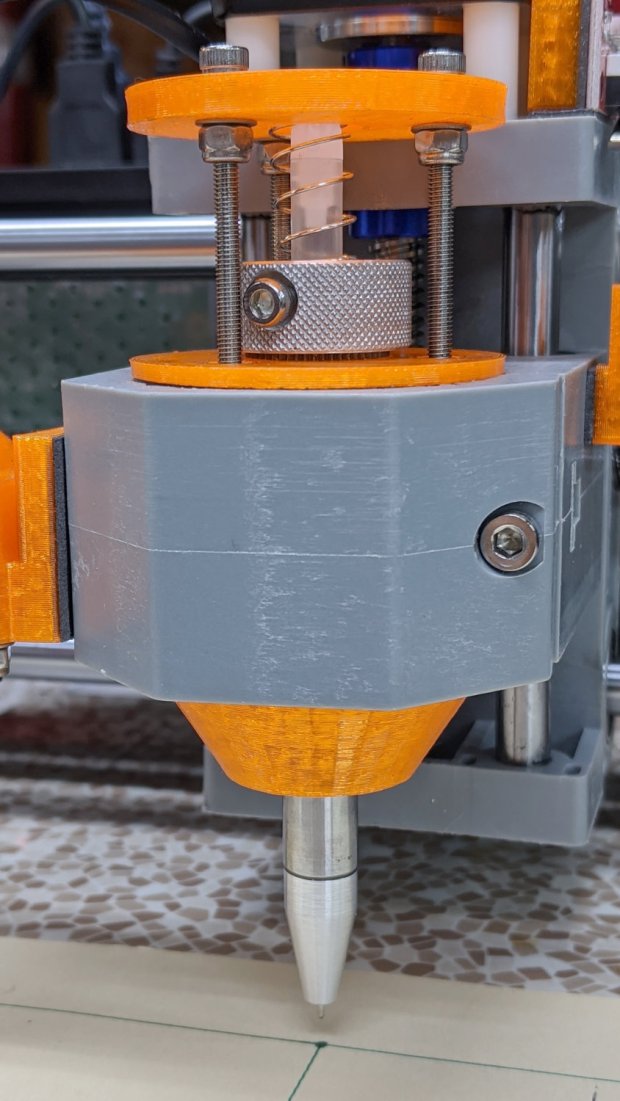
// CNC 3018-Pro Run-Hold Switches |
|
// Ed Nisley – KE4ZNU – 2020-01 |
|
|
|
Layout = "Build"; // [Show,Build,ProjectionX,ProjectionY,ProjectionZ,Block] |
|
|
|
/* [Hidden] */ |
|
|
|
ThreadThick = 0.25; |
|
ThreadWidth = 0.40; |
|
|
|
HoleWindage = 0.2; |
|
|
|
Protrusion = 0.1; // make holes end cleanly |
|
|
|
function IntegerMultiple(Size,Unit) = Unit * ceil(Size / Unit); |
|
|
|
ID = 0; |
|
OD = 1; |
|
LENGTH = 2; |
|
|
|
inch = 25.4; |
|
|
|
//———————- |
|
// Dimensions |
|
|
|
RodScrewOffset = [22,0,-14.5]; // X=left edge, Y=dummy, Z=from top edge |
|
BeamScrewOffset = [50,0,-10]; |
|
LeadScrewOffset = [RodScrewOffset.x,0,-45]; // may be off the bottom; include anyway |
|
LeadScrew = [8.0,10.0,5.0]; // ID=actual, OD=clearance, LENGTH=stick-out |
|
|
|
Screw = [5.0,10.0,6.0]; // M5 SHCS, OD=washer, LENGTH=washer+head |
|
ScrewSides = 8; // hole shape |
|
|
|
WallThick = 3.0; // minimum wall thickness |
|
FlangeThick = 5.0; // flange thickness |
|
|
|
Switch = [15.0 + 2*HoleWindage,15.0 + 2*HoleWindage,12.5]; // switch body |
|
SwitchCap = [17.5,17.5,12.0]; // … pushbutton |
|
SwitchClear = SwitchCap + [2*2.0,2*2.0,Screw[OD]/(2*cos(180/ScrewSides))]; |
|
SwitchContacts = 5.0; // contacts below switch |
|
SwitchBase = SwitchContacts + Switch.z; // bottom to base of switch |
|
|
|
MountOffset = abs(RodScrewOffset.z) + SwitchClear.z; // top of switch mounting plate |
|
|
|
FrameWidth = 60.0; // CNC 3018-Pro upright |
|
FrameRadius = 10.0; // … front corner rounding |
|
|
|
CornerRadius = 5.0; // pretty part rounding |
|
CornerSquare = 10; // dummy for square corner |
|
|
|
MountOAL = [FrameWidth, // covers machine frame |
|
2*FlangeThick + 2*Screw[LENGTH] + SwitchClear.y, // clear screw heads |
|
MountOffset + Switch.z + SwitchContacts |
|
]; |
|
echo(str("MountOAL: ",MountOAL)); |
|
|
|
SwitchOC = [MountOAL.x/2,FlangeThick + 2*Screw[LENGTH] + SwitchClear.y/2,0]; |
|
|
|
CableOD = 5.0; |
|
|
|
NumSides = 2*3*4; |
|
|
|
Gap = 2.0; // between build layout parts |
|
|
|
//———————- |
|
// Useful routines |
|
|
|
module PolyCyl(Dia,Height,ForceSides=0) { // based on nophead's polyholes |
|
|
|
Sides = (ForceSides != 0) ? ForceSides : (ceil(Dia) + 2); |
|
FixDia = Dia / cos(180/Sides); |
|
cylinder(r=(FixDia + HoleWindage)/2, |
|
h=Height, |
|
$fn=Sides); |
|
} |
|
|
|
// Projections for intersections |
|
|
|
module ProjectionX() { |
|
|
|
sr = CornerSquare/2; |
|
|
|
rotate([0,90,0]) rotate([0,0,90]) |
|
linear_extrude(height=FrameWidth,convexity=3) |
|
// mirror([1,0]) // mount on motor side of gantry |
|
union() { |
|
translate([0,-MountOAL.z]) |
|
square([FlangeThick,MountOAL.z]); |
|
hull() { |
|
translate([MountOAL.y – CornerRadius,-MountOffset + SwitchCap.z – CornerRadius]) |
|
circle(r=CornerRadius,$fn=NumSides); |
|
translate([sr,-MountOffset + SwitchCap.z – sr]) |
|
square(CornerSquare,center=true); |
|
translate([sr,-MountOAL.z + sr]) |
|
square(CornerSquare,center=true); |
|
translate([MountOAL.y – sr,-MountOAL.z + sr]) |
|
square(CornerSquare,center=true); |
|
} |
|
} |
|
} |
|
|
|
module ProjectionY() { |
|
|
|
sr = CornerSquare/2; |
|
|
|
rotate([90,0,0]) |
|
translate([0,0,-FrameWidth]) |
|
difference() { |
|
linear_extrude(height=2*FrameWidth,convexity=3) |
|
hull() { |
|
translate([FrameRadius,-FrameRadius]) |
|
circle(r=FrameRadius,$fn=NumSides); |
|
translate([FrameWidth – sr,-sr]) |
|
square(CornerSquare,center=true); |
|
translate([sr,-MountOAL.z + sr]) |
|
square(CornerSquare,center=true); |
|
translate([MountOAL.x – sr,-MountOAL.z + sr]) |
|
square(CornerSquare,center=true); |
|
} |
|
translate([RodScrewOffset.x,RodScrewOffset.z,-Protrusion]) |
|
rotate(180/ScrewSides) PolyCyl(Screw[ID],2*(FrameWidth + Protrusion),ScrewSides); |
|
for (j=[-FlangeThick,FrameWidth + FlangeThick]) |
|
translate([RodScrewOffset.x,RodScrewOffset.z,j]) |
|
rotate(180/ScrewSides) PolyCyl(Screw[OD],FrameWidth,ScrewSides); |
|
|
|
translate([BeamScrewOffset.x,BeamScrewOffset.z,-Protrusion]) |
|
rotate(180/ScrewSides) PolyCyl(Screw[ID],2*(FrameWidth + Protrusion),ScrewSides); |
|
for (j=[-FlangeThick,FrameWidth + FlangeThick]) |
|
translate([BeamScrewOffset.x,BeamScrewOffset.z,j]) |
|
rotate(180/ScrewSides) PolyCyl(Screw[OD],FrameWidth,ScrewSides); |
|
|
|
translate([LeadScrewOffset.x,LeadScrewOffset.z,FrameWidth – LeadScrew[LENGTH]]) |
|
rotate(180/ScrewSides) PolyCyl(LeadScrew[OD],2*LeadScrew[LENGTH],ScrewSides); |
|
} |
|
} |
|
|
|
|
|
module ProjectionZ() { |
|
translate([0,0,-MountOAL.z]) |
|
// mirror([0,1]) // mount on motor side of gantry |
|
difference() { |
|
linear_extrude(height=MountOAL.z,convexity=3) |
|
difference() { |
|
square([MountOAL.x,MountOAL.y]); |
|
translate([SwitchOC.x/2,SwitchOC.y]) |
|
square([Switch.x,Switch.y],center=true); |
|
translate([3*SwitchOC.x/2,SwitchOC.y]) |
|
square([Switch.x,Switch.y],center=true); |
|
} |
|
for (i=[-1,1]) |
|
translate([i*SwitchOC.x/2 + MountOAL.x/2,SwitchOC.y,SwitchBase + MountOAL.z/2]) |
|
cube([SwitchClear.x,SwitchClear.y,MountOAL.z],center=true); |
|
|
|
translate([-Protrusion,SwitchOC.y – 2*CableOD – Switch.y/2,-Protrusion]) |
|
cube([MountOAL.x + 2*Protrusion,CableOD,CableOD + Protrusion],center=false); |
|
|
|
for (i=[-1,1]) |
|
translate([i*SwitchOC.x/2 + MountOAL.x/2,SwitchOC.y – SwitchCap.y/2,CableOD/2 – Protrusion]) |
|
cube([CableOD,SwitchClear.y/2,CableOD + Protrusion],center=true); |
|
|
|
translate([SwitchOC.x/2,SwitchOC.y – CableOD/2,-Protrusion]) |
|
cube([SwitchOC.x,CableOD,CableOD + Protrusion],center=false); |
|
|
|
} |
|
} |
|
|
|
module Block() { |
|
intersection() { |
|
ProjectionX(); |
|
ProjectionY(); |
|
ProjectionZ(); |
|
} |
|
} |
|
|
|
|
|
//- Build things |
|
|
|
if (Layout == "ProjectionX") |
|
ProjectionX(); |
|
|
|
if (Layout == "ProjectionY") |
|
ProjectionY(); |
|
|
|
if (Layout == "ProjectionZ") |
|
ProjectionZ(); |
|
|
|
if (Layout == "Block") |
|
Block(); |
|
|
|
if (Layout == "Show") { |
|
translate([-MountOAL.x/2,-MountOAL.y/2,MountOAL.z]) { |
|
Block(); |
|
translate([MountOAL.x/2 + SwitchOC.x/2,SwitchOC.y,SwitchCap.z/2 – MountOAL.z + SwitchBase + 0*Switch.z]) |
|
color("Yellow",0.75) |
|
cube(SwitchCap,center=true); |
|
translate([MountOAL.x/2 – SwitchOC.x/2,SwitchOC.y,SwitchCap.z/2 – MountOAL.z + SwitchBase + 0*Switch.z]) |
|
color("Green",0.75) |
|
cube(SwitchCap,center=true); |
|
} |
|
} |
|
|
|
if (Layout == "Build") |
|
translate([-MountOAL.x/2,-MountOAL.y/2,MountOAL.z]) |
|
Block(); |
|
|