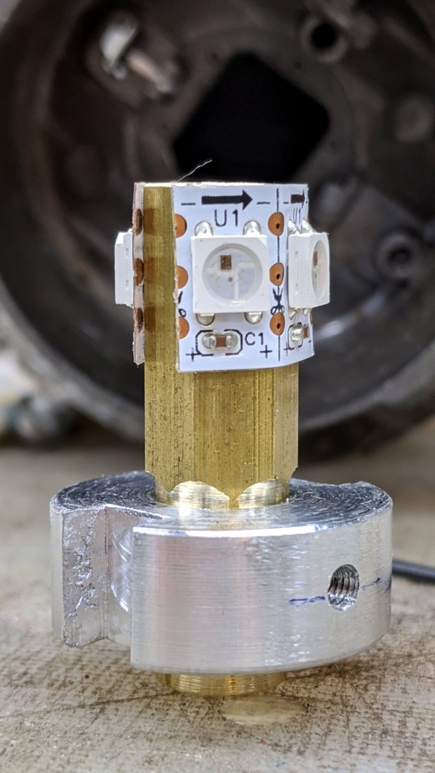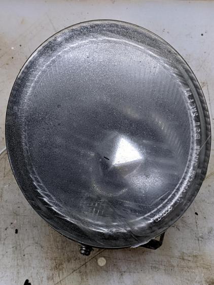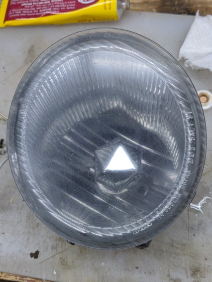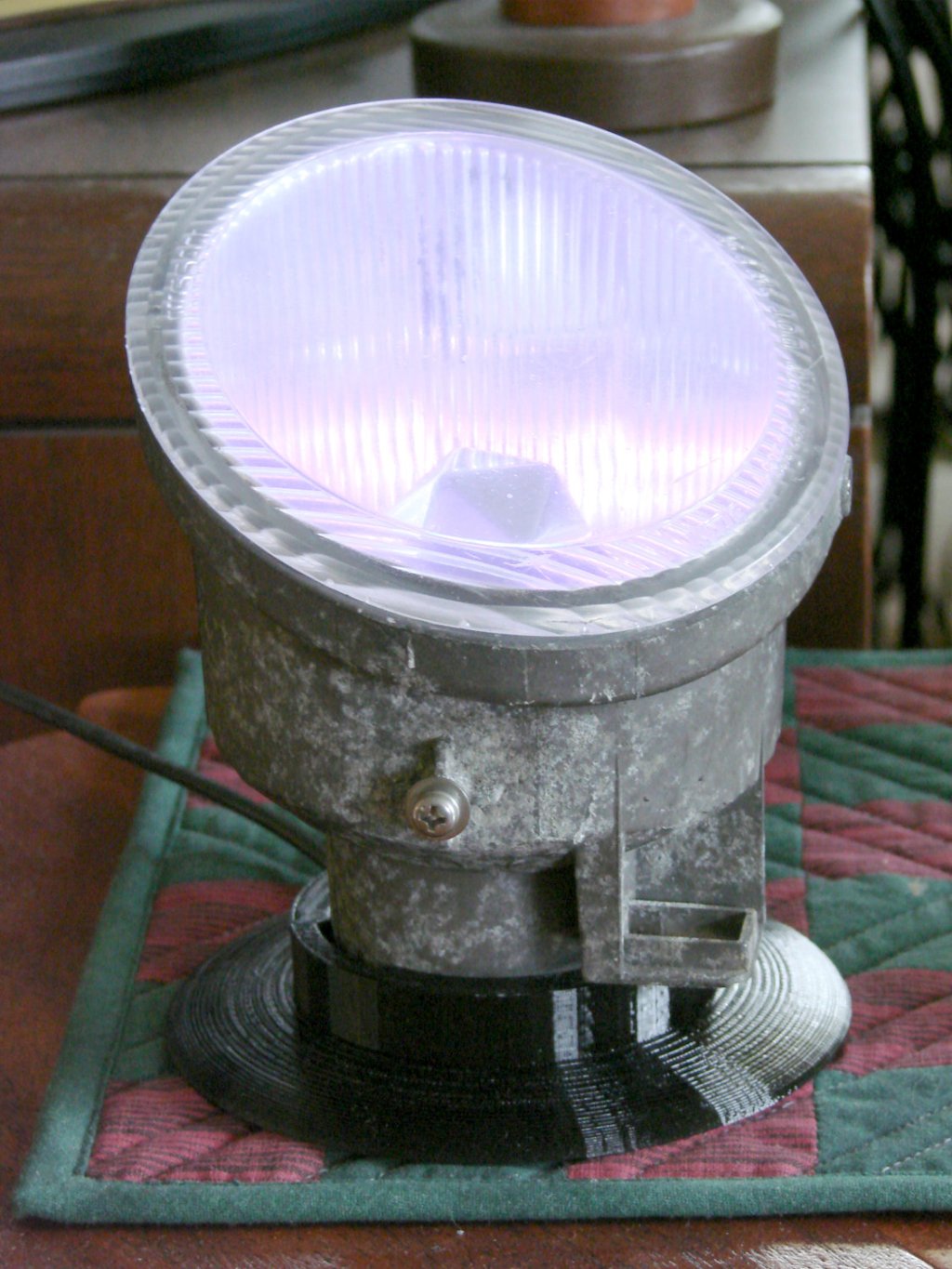
The Nissan fog lamp looks pretty good pointing at the ceiling:

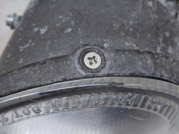
I briefly considered sandblasting the shell to knock back the corrosion, but came to my senses: this is art!
The shell has a bayonet mount intended for the cable connector, but a bout of solid modeling produced a matching twist-lock desk stand:
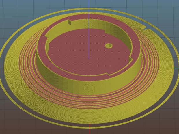
The locking dogs overhang little enough, relative to their diameter, to let the thing build without internal supports. Took about three hours without any intervention at all.
The little hole matches up with the slot on the bottom holding a USB cable bringing power from a wall charger:
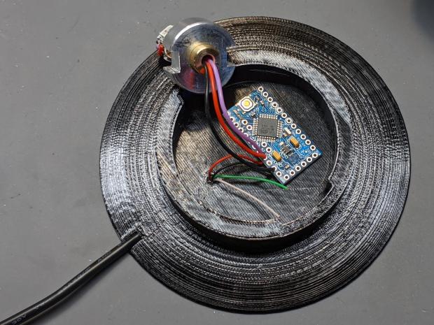
It’s a knockoff Arduino Pro Mini without the USB interface found on a Nano, so the USB data wires don’t connect to anything.
The base might look better under a layer of (black?) epoxy, although I’m definitely a fan of those brutalist 3D printed striations.
The OpenSCAD source code as a GitHub Gist:
| // Nissan Fog Light Base | |
| // Ed Nisley KE4ZNU 2020-04-20 | |
| /* [Hidden] */ | |
| ThreadThick = 0.25; | |
| ThreadWidth = 0.40; | |
| HoleWindage = 0.2; | |
| function IntegerMultiple(Size,Unit) = Unit * ceil(Size / Unit); | |
| Protrusion = 0.1; // make holes end cleanly | |
| //———————- | |
| // Dimensions | |
| ID = 0; | |
| OD = 1; | |
| LENGTH = 2; | |
| /* [Fog Light] */ | |
| ShellBase = [49.0,55.0,10.0]; | |
| Dog = [55.0,60.0,7.0]; | |
| DogWidth = 21.0; | |
| DogAngle = atan(DogWidth / ShellBase[ID]); | |
| echo(str("Dog angle: ",DogAngle)); | |
| ReflectorOD = 90.0; | |
| LensOD = 110.0; | |
| LensAngle = -90; // peak relative to dogs | |
| WallThick = 4.0; | |
| BaseThick = 2*WallThick; | |
| CableOD = 3.5; | |
| $fn = 3*4*5; | |
| //——————- | |
| // Useful shapes | |
| module Dogs(h=Dog[LENGTH]) { | |
| translate([0,0,h/2]) | |
| intersection() { | |
| cube([Dog[OD],DogWidth,h],center=true); | |
| cylinder(d=Dog[OD],h=h,center=true); | |
| } | |
| } | |
| //——————- | |
| // Build it | |
| difference() { | |
| union() { | |
| cylinder(d=(Dog[OD] + 2*WallThick),h=(BaseThick + ShellBase[LENGTH])); | |
| intersection() { | |
| resize([0,0,2*BaseThick]) | |
| sphere(d=LensOD); | |
| translate([0,0,BaseThick/2]) | |
| cube([2*LensOD,2*ReflectorOD,BaseThick],center=true); | |
| } | |
| } | |
| translate([0,0,BaseThick]) | |
| cylinder(d=ShellBase[OD],h=ShellBase[LENGTH] + Protrusion); | |
| translate([0,0,BaseThick]) { | |
| Dogs(); | |
| rotate(1.5*DogAngle) | |
| Dogs(); | |
| rotate(2*DogAngle) | |
| Dogs(2*ShellBase[LENGTH]); | |
| } | |
| rotate(LensAngle) | |
| translate([0.75*ShellBase[ID]/2,0,-Protrusion]) { | |
| cylinder(d=CableOD,h=2*BaseThick,$fn=8); | |
| translate([LensOD/2,0,CableOD/2]) | |
| cube([LensOD,CableOD,CableOD + Protrusion],center=true); | |
| } | |
| translate([31,0,ThreadThick-Protrusion]) | |
| cube([23.0,55.0,2*ThreadThick],center=true); | |
| } | |
| linear_extrude(height=2*ThreadWidth + Protrusion) { | |
| translate([32,0,-Protrusion]) | |
| rotate(-90) mirror([1,0,0]) | |
| text(text="Ed Nisley",size=6,font="Arial:style:Bold",halign="center"); | |
| translate([23,0,-Protrusion]) | |
| rotate(-90) mirror([1,0,0]) | |
| text(text="softsolder.com",size=5,font="Arial:style:Bold",halign="center"); | |
| } |