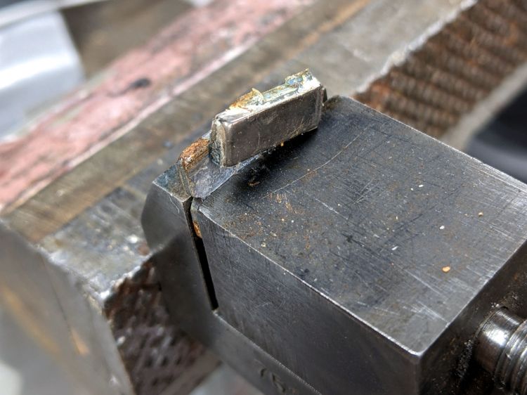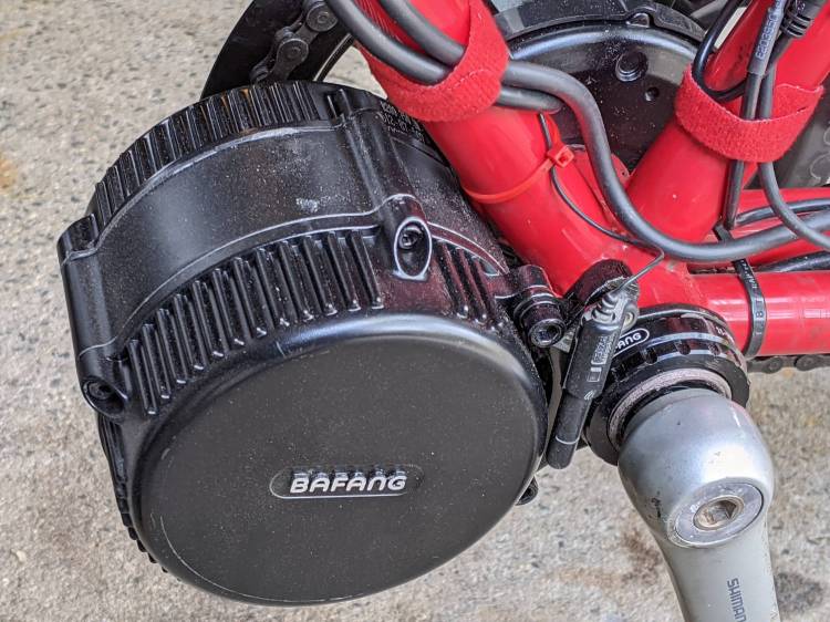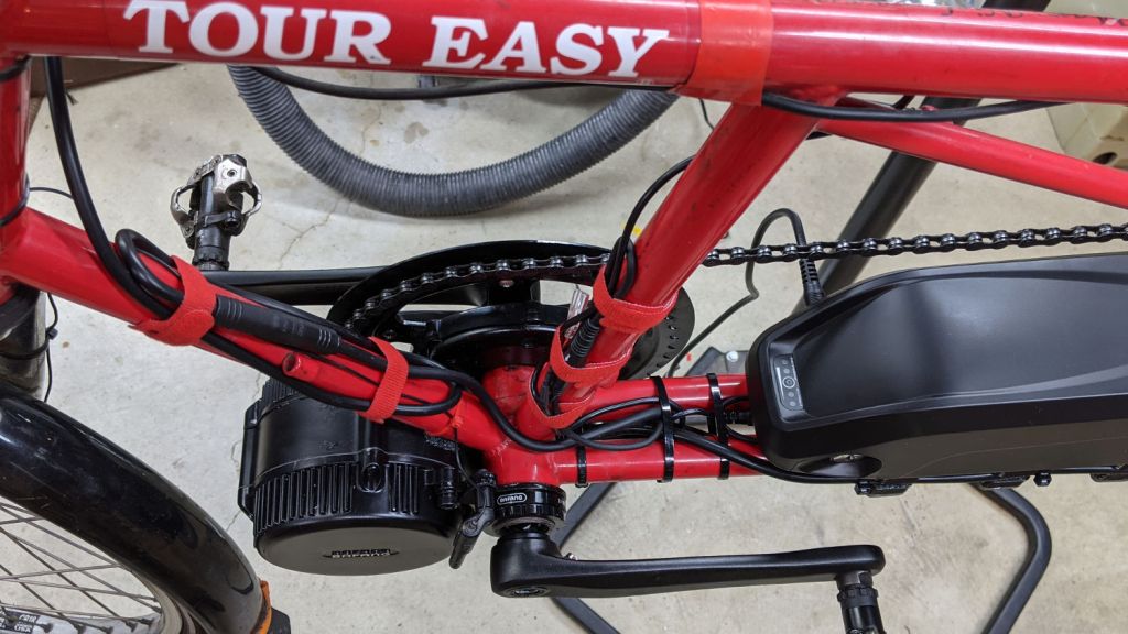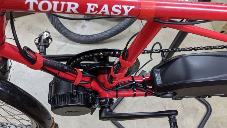
Changing (“programming”) the Bafang BBS02 motor controller parameters requires a USB-to-serial adapter with a connector matching the end of the cable from the motor to the display. While you can buy such things directly from the usual randomly named Amazon sellers, I happen to have a wide variety of bare adapter boards, so I just bought a display extender cable and cut it in half to get the connector; you can apparently buy pigtailed connectors (for more than the price of an extender) if you dislike cutting cables in half.
Various documents provide versions of the canonical illustration of the motor end of the display cable, as ripped from Penoff’s original documentation:

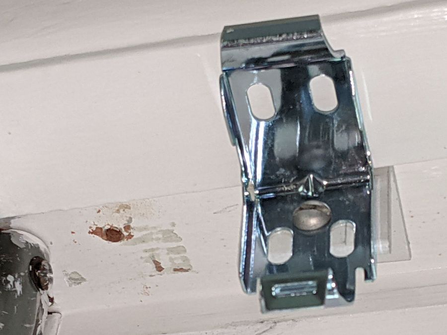
The pin colors correspond to the wiring inside the motor cable, but the extender uses different colors, because nobody will ever know:
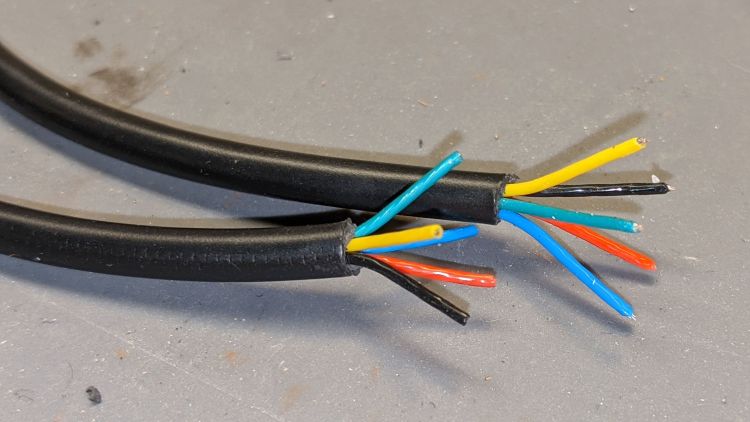
A bit of work with a continuity meter gave the pinout:
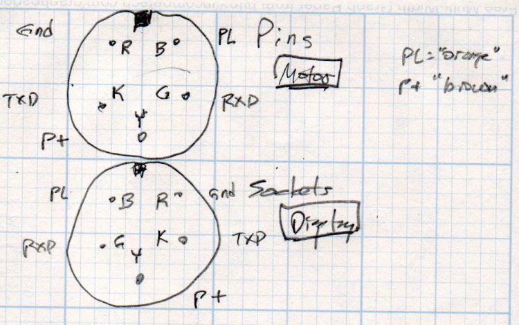
Don’t trust stuff you read on the Intertubes: make your own measurements and draw your own diagrams!
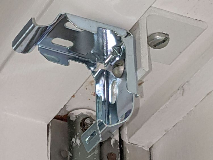
You want the cable end carrying the sockets to mate with the pins on the motor cable (coming in from the left):
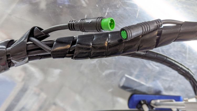
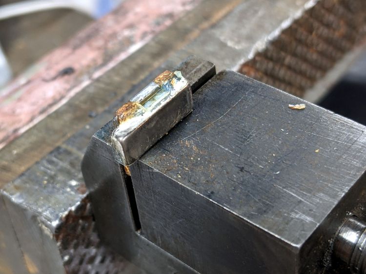
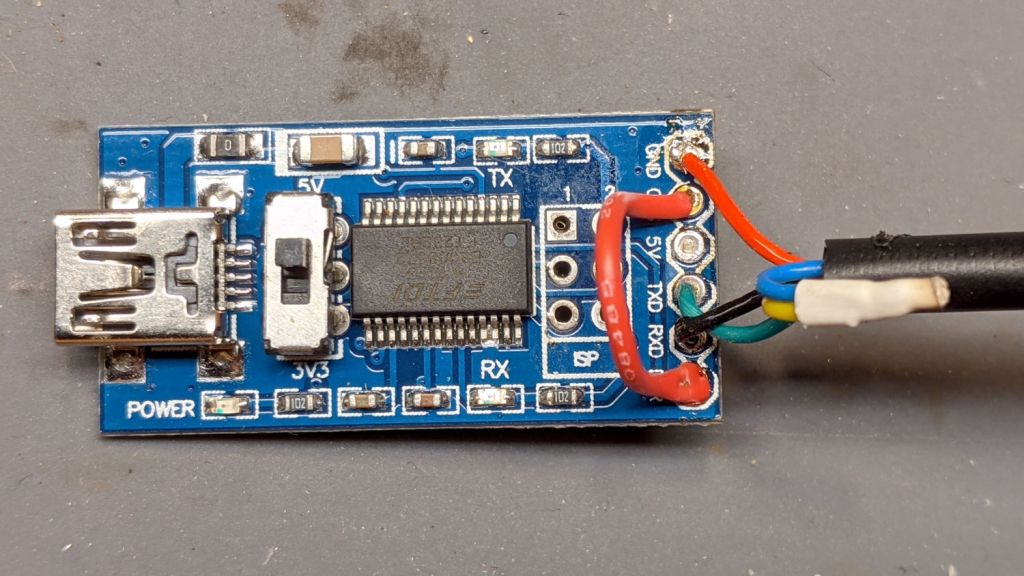
Soldering the cable to a known-counterfeit FTDI USB adapter went swimmingly:

Note that the yellow-blue connection carries the full 48 V from the battery and may or may not have any current limiting / fusing / protection, so be a little more careful than usual in your wiring layout.
The red jumper from DTR to CTS, shown in all the Amazon and eBay listIngs, turns out to be unnecessary.
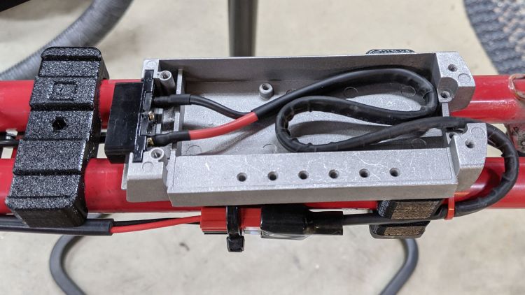
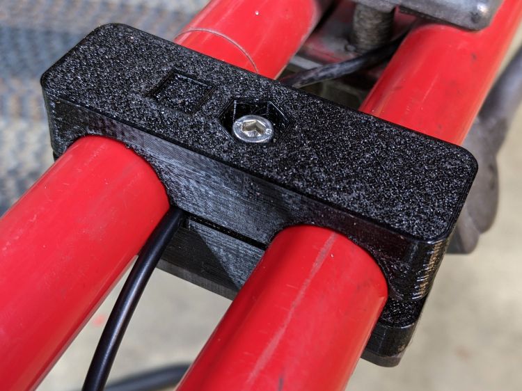
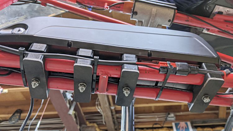
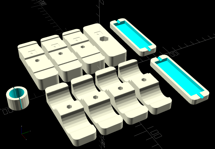
A quick and dirty case (eventually held together with generous hot-melt glue blobs) protects the PCB and armors the cables:

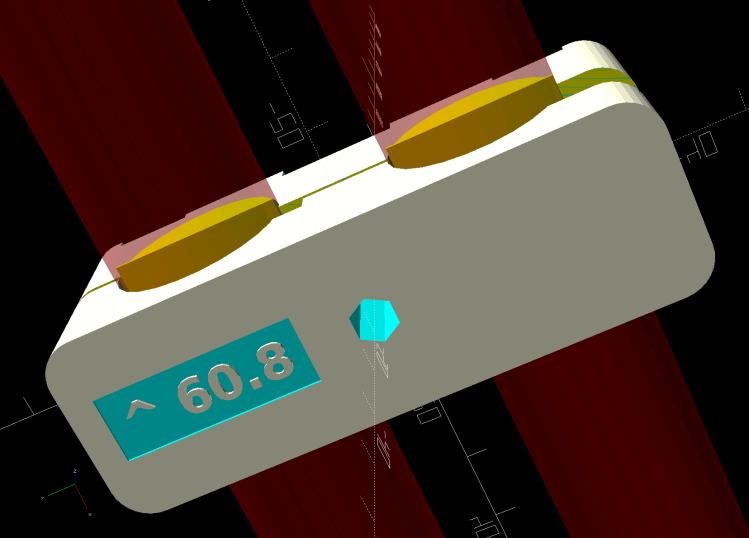
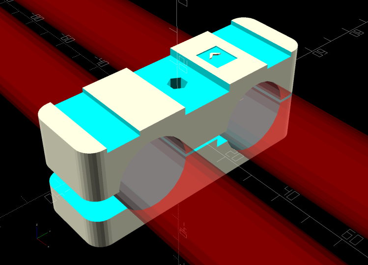
The solid model over on the right looks about like you’d expect:
Most of the instructions will tell you to hot-plug the cable to the motor with the battery connected, which strikes me as foolhardy; not all of those pins make contact in the right order, which means you will slap 50-odd volts across the wrong parts of the circuitry.
Instead:
- Disconnect the battery
- Unplug the display
- Plug the adapter cable into the motor connector
- Plug the USB cable into the Token Windows Laptop
- Reconnect the battery
- Fire up the “programming” routine
- Send the new configuration to the motor controller
- Disconnect the battery
- Unplug the adapter cable
- Reconnect the display cable
- Reconnect the battery
Makes more sense to me, even if it’s more tedious.
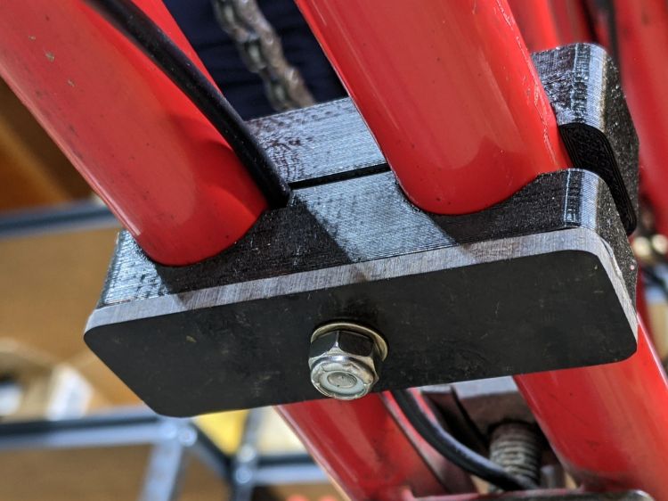
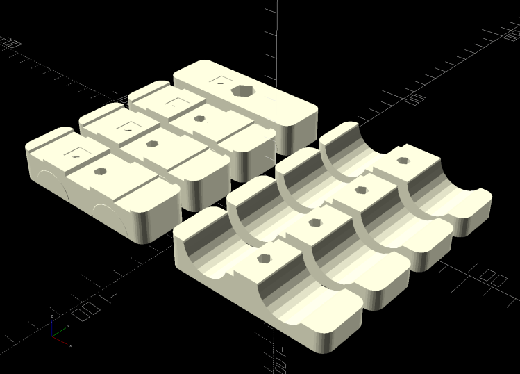
Tuck this OpenSCAD source code for the case into the original program that produces the battery mounts:
Layout = "Build";               // [Frame,Block,Show,Build,Bushing,Cateye,Case]

… snippage …

// Programming cable case

ProgCavity = [70.0,19.0,10.0];
ProgBlock = [85.0,25.0,15.0];
ProgCableOD = 4.0;

module ProgrammerCase() {

    difference() {
        hull() {
            for (i=[-1,1], j=[-1,1])
                translate([i*(ProgBlock.x/2 - CornerRadius),j*i*(ProgBlock.y/2 - CornerRadius),-ProgBlock.z/2])
                    cylinder(r=CornerRadius,h=ProgBlock.z,$fn=12);
            }
        translate([-ProgBlock.x,0,0])
            rotate([0,90,0])
                PolyCyl(ProgCableOD,3*ProgBlock.x,6);
        cube(ProgCavity,center=true);
    }
}

// Half case sections for printing

module HalfCase(Section = "Upper") {

    intersection() {
       translate([0,0,ProgBlock.z/4])
            cube([2*ProgBlock.x,2*ProgBlock.y,ProgBlock.z/2],center=true);
        if (Section == "Upper")
            translate([0,0,-Kerf/2])
                ProgrammerCase();
        else
            translate([0,0,ProgBlock.z/2])
                ProgrammerCase();
    }
}

… snippage …

// tuck this into the Build conditional

    translate([0,3*Block.x,0]) {

        translate([gap*ProgBlock.x/2,0,ProgBlock.z/2])
            rotate([180,0,0])
                HalfCase("Upper");
        translate([-gap*ProgBlock.x/2,0,0])
            HalfCase("Lower");