The Smell of Molten Projects in the Morning

Ed Nisley's Blog: Shop notes, electronics, firmware, machinery, 3D printing, laser cuttery, and curiosities. Contents: 100% human thinking, 0% AI slop.

Category: Machine Shop

Mechanical widgetry

  • Microscope Stage Positioner: Rigid MakerBeam Edition

    Microscope Stage Positioner: Rigid MakerBeam Edition

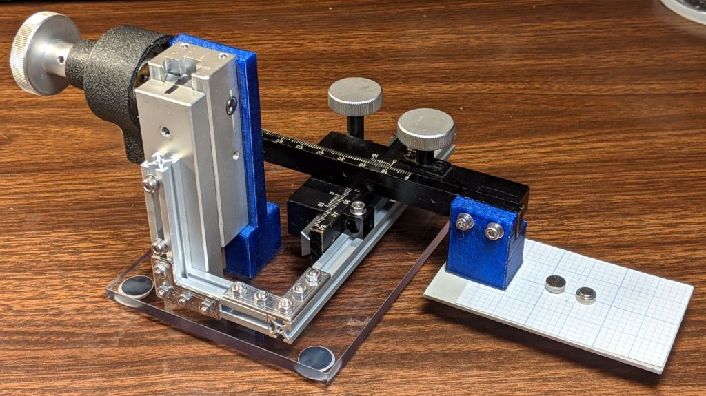
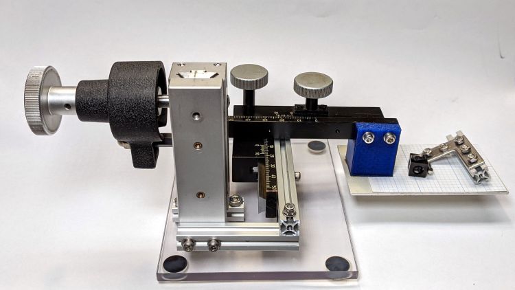
    Rebuilding the XYZ stage positioner with MakerBeam aluminum struts, but without the steel brackets, produce a much more rigid result:

    Microscope Stage Positioner - rigid Makerbeam
    Microscope Stage Positioner – rigid Makerbeam

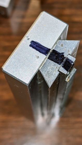
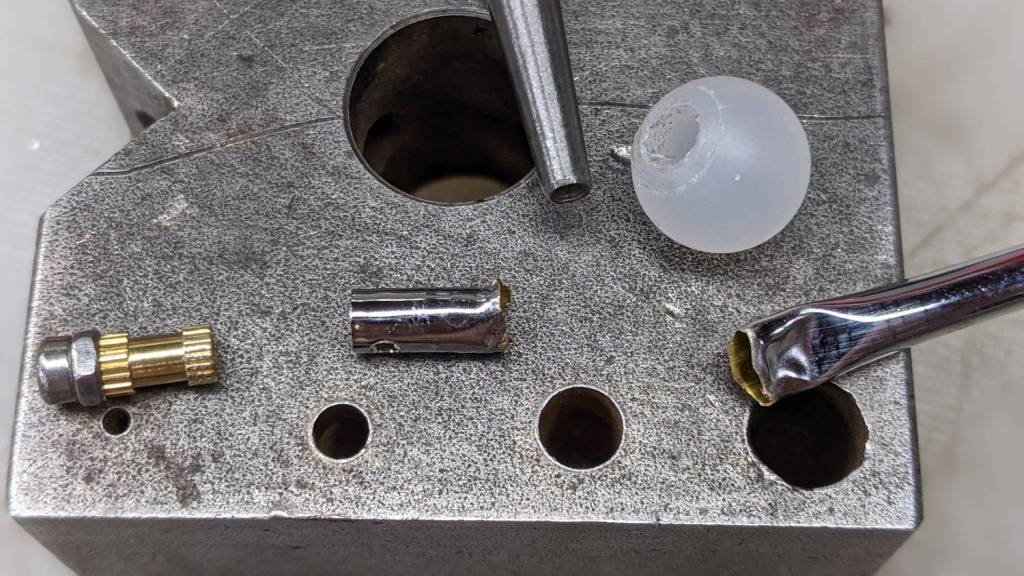
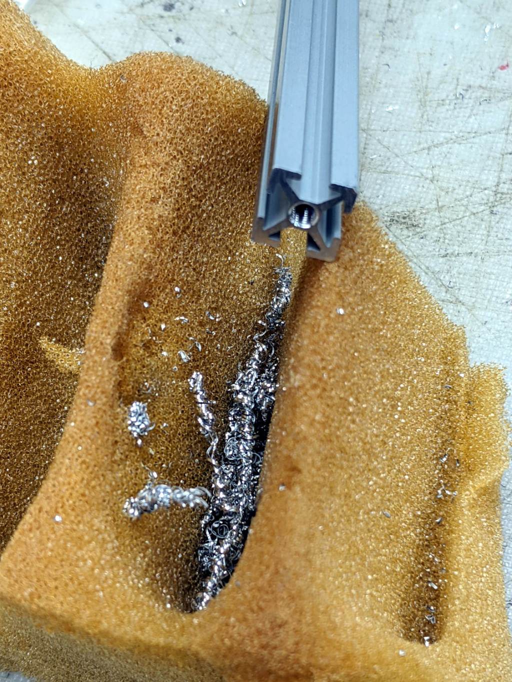
    This requires drilling holes through the extrusions:

    Microscope Stage Positioner - Makerbeam drilling
    Microscope Stage Positioner – Makerbeam drilling

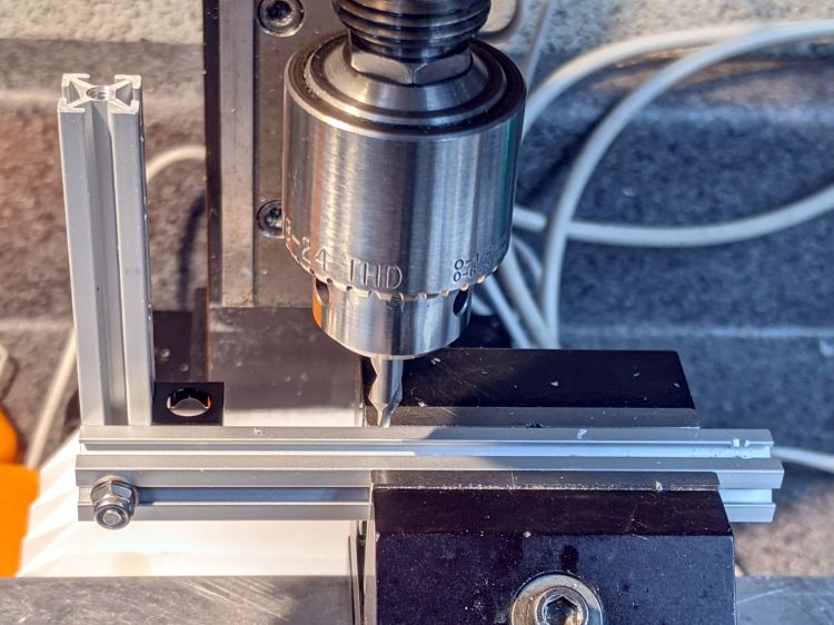
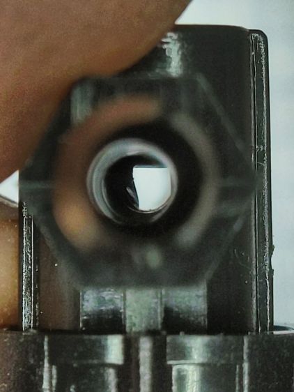
    Running the center drill down until it just nicks the sides produces enough of a pilot hole through the center section to capture the 3 mm drill. If I had to drill enough holes to make a fixture worthwhile, I could probably eliminate the divots.

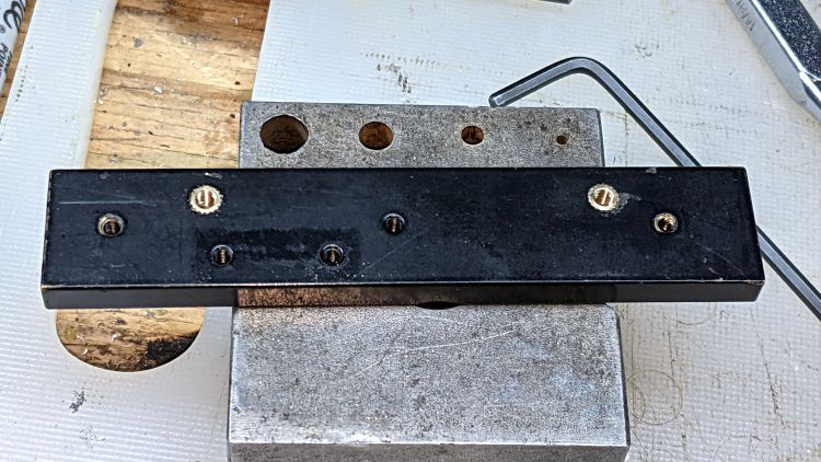
    Two more holes + epoxied M3 brass inserts attached the 60 mm beam directly to the Z Axis stage, thereby eliminating the vertical beam and a steel bracket:

    Microscope Stage Positioner - Makerbeam joints
    Microscope Stage Positioner – Makerbeam joints

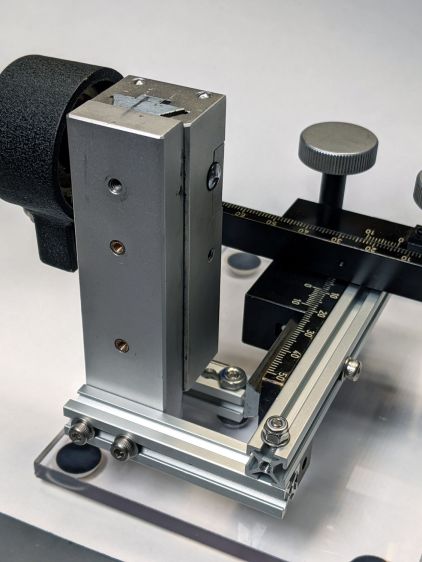
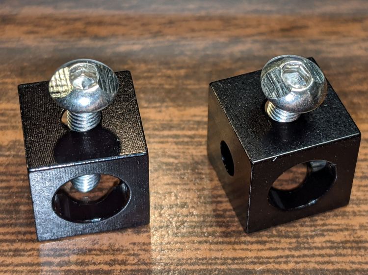
    The M3 SHCS attaching the 100 mm beam goes through both beams. I think you could get the same result with a Tee Nut or a 12 mm Square Head bolt, should you have those lying around and don’t want to drill another hole. The Corner Cube screwed into both beams prevents rotation and helps ensure perpendicularity.

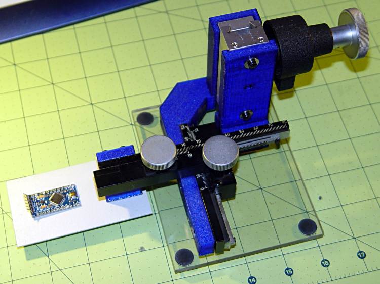
    The Y stage now attaches directly to the beam, rather than through a pair of Corner Cubes, because I realized I wasn’t ever going to adjust its position.

    The Z Axis stage stands on the plastic plate through a hellish mixture of metric and USA-ian screws. Basically, the 6-40 screws into the stage were long enough, the 6-32 screws through the plate fit the existing holes, and M3 screws are for MakerBeam:

    Microscope Stage Positioner - Z Axis base
    Microscope Stage Positioner – Z Axis base

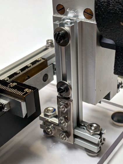
    To my utter astonishment, the threads in the end of the vertical beam had the proper alignment to let a Square Head bolt snug the beam against the 40 mm beam on the plate. As a result, the L Bracket just prevents the vertical beam from turning on the screw and the combination is as rigid as you (well, I) could want.

    The 40 mm beam has two spurious holes, because I thought I could avoid drilling another hole in the baseplate. Nobody will ever notice.

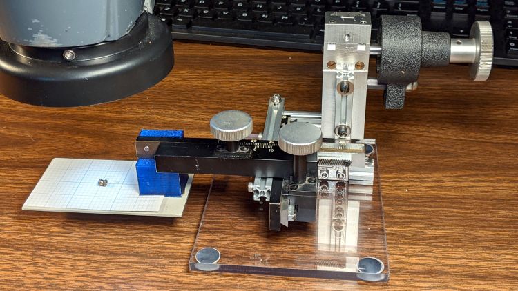
    After squaring and tightening everything, the 100 mm beam along the Y Axis is now horizontal within 0.2 mm and the X Axis is horizontal to better than I can measure.

    It’s definitely Good Enough™ for me:

    Microscope Stage Positioner - in use
    Microscope Stage Positioner – in use

    Remember, nothing exceeds like excess …

  • Microscope Stage Positioner: MakerBeam Rebuild MVP

    Microscope Stage Positioner: MakerBeam Rebuild MVP

    Over the course of half a decade (!), the 3D printed arm on the XYZ positioner I use with the stereo zoom microscope sagged:

    Microscope Stage Positioner - PETG creep angle
    Microscope Stage Positioner – PETG creep angle

    It’s about what you’d expect from a plastic beam carrying a big lump of brass and steel:

    Microscope Stage Positioner
    Microscope Stage Positioner

    The near side of that arm (the -Y end) drooped about 5 mm below than the side nearest the Z axis slide, so it was time for an update.

    Having some MakerBeam ready to hand, this didn’t take long:

    Microscope Stage Positioner - Makerbeam overview
    Microscope Stage Positioner – Makerbeam overview

    Protip: before dismantling a fitted slide, mark one end so you know how to put it back together. Bonus points for taking a picture:

    Microscope Stage Positioner - slide marking
    Microscope Stage Positioner – slide marking

    Double bonus points for writing a blog post.

    Rather than fight with the existing fine-pitch USA-ian screws, I drilled out their threaded holes:

    Microscope Stage Positioner - Y slide drilling
    Microscope Stage Positioner – Y slide drilling

    And epoxied 3 mm brass inserts in their place:

    Microscope Stage Positioner - Y slide M3 inserts
    Microscope Stage Positioner – Y slide M3 inserts

    Those holes match up with a pair of corner cubes normally appearing on the end of the beams:

    Microscope Stage Positioner - BHCS mods for Makerbeam
    Microscope Stage Positioner – BHCS mods for Makerbeam

    It turns out M3 button head cap screws will slide into the beams if you file the slightest angle on opposite sides of the button, although a small bag of tiny tee nuts should arrive in a while.

    Then a variety of brackets spliced everything together:

    Microscope Stage Positioner - Makerbeam detail
    Microscope Stage Positioner – Makerbeam detail

    Although it looks strictly from industrial, it actually wasn’t much better than the plastic edition and, in fact, the beam supporting the XY slides sagged about the same 5 mm. The plastic upright post also contributed a bit of wobble.

    It turns out that the extruded aluminum beams have plenty of longitudinal and torsional stiffness, but all those flat steel fittings don’t.

    There’s a way to work with the beam strengths, rather than against them, but that’s a story for another day …

  • Bicycle Helmet Mirror: Stalk Repair

    Bicycle Helmet Mirror: Stalk Repair

    The mirror on my bike helmet snagged on a mesh fence while walking the bike to Mary’s garden:

    Helmet Mirror - bent stalk
    Helmet Mirror – bent stalk

    One of the good things about building your own stuff is that you have all the parts when something breaks:

    Helmet Mirror - damaged parts
    Helmet Mirror – damaged parts

    The decorative M2 screw and insert pulled out of the ball. The rim of the nail set punch (intruding from the top) just barely caught the edge of the stub inside the ball, so a few taps could extract it. A Dremel cutoff wheel peeled the crumpled end off the stalk.

    Reassembly proceeded without incident:

    Helmet Mirror - installed
    Helmet Mirror – installed

    The bizarrely blurred mirror over on the left comes from the Pixel phone camera app deciding this was a Portrait, applying a background blur, and running into trouble with those hard edges in the foreground. The camera app has a distinct Portrait mode that, perhaps, I inadvertently engaged while fumbling around.

  • Aceco FC1002 Battery Re-replacement

    Aceco FC1002 Battery Re-replacement

    My old Aceco FC1002 frequency meter stopped working without being plugged into the charger. It runs from a quartet of NiMH cells taped into a tray I made seven years ago:

    Aceco FC1002 - hacked battery
    Aceco FC1002 – hacked battery

    One of the cells was completely dead and the other three will blink LEDs for the rest of their lives.

    The Eneloops have trickled down from the DSC-H5 and still seem perfectly fine for ordinary use.

    The faceplate bears the scars of its cracked acrylic (?) coating, so I pushed it out, traced the outline on a flat piece of polypropylene clamshell packaging, cut it out, and stuck it in place with tapeless sticky:

    Aceco FC1002 - polypropylene faceplate
    Aceco FC1002 – polypropylene faceplate

    That removes the branding, but IMO improves the appearance.

    It should continue working for another half decade or so!

  • MakerBeam Swarf Cleanout

    MakerBeam Swarf Cleanout

    Playing with Evaluating a recently arrived MakerBeam Starter Kit revealed swarf snarls in the tapped end holes. After giving up on a needle-nose tweezer, a compressed air blow gun expelled the mess from a handful of short beams:

    Makerbeam - internal swarf A
    Makerbeam – internal swarf A

    A scrap of acoustic foam backstopped the rest of the assortment:

    Makerbeam - internal swarf B
    Makerbeam – internal swarf B

    Which doesn’t account for the scattering of swarf and oil blown elsewhere in the Basement Shop.

    Perhaps a bad day in the MakerBeam factory?

    Protip: wear eye protection when using compressed air!

  • Dripworks Micro-Flow Valves: QC FAIL

    Dripworks Micro-Flow Valves: QC FAIL

    We recently installed a Dripworks drip irrigation system for Mary’s garden and, of course, pre-assembled the emitter / dripline tubing, fittings, and supply / filter / plumbing for each of the beds in the Basement Shop. A few days after burying the main lines, plumbing the filter + pressure regulator, and plugging in half a dozen bed assemblies, Mary noticed some emitter tubes weren’t delivering any water and other beds seemed too dry.

    N.B.: We bought everything directly from Dripworks. This is not counterfeit crap from a sketchy Amazon seller.

    I cut the dripline just downstream of the Micro-Flow valve on a completely dry bed, whereupon no water emerged. Cutting the supply tube just upstream of the valve produced a jet squirting halfway along the bed. I tried and failed to blow air through the valve: it was completely blocked despite being in the “open” position. I installed another valve and the emitter tube started working properly.

    I sat down at the kitchen table with a bag of unused valves and peered through them (the pix are through the microscope):

    Dripworks valve - mostly open lumen
    Dripworks valve – mostly open lumen

    That’s one of the better-looking valves, with only a little mold flash in the lumen.

    Partially occluded lumens were more typical:

    Dripworks valve - partially occluded lumen
    Dripworks valve – partially occluded lumen

    Quite a few were almost completely obstructed:

    Dripworks valve - mostly occluded lumen
    Dripworks valve – mostly occluded lumen

    For lack of better instrumentation, I blew through the valves and sorted them by effort:

    Dripworks valve - sorted by blockage
    Dripworks valve – sorted by blockage

    Two of the valves in the group on the left are completely blocked, with the others mostly blocked.

    The middle group has enough mold flash to produce noticeable resistance to the air flow. I think water would have more trouble getting through, but the emitters would at least look like they’re delivering water.

    The group on the right has mostly unblocked valves, with visible mold flash but little restriction.

    I have no way to measure the actual water flow, so it’s entirely possible the QC spec allows considerable blockage while still delivering enough water to the emitters. More likely, the spec assumes a clear lumen and the mold flash is a total QC faceplant; it’s obviously not a controlled quantity.

    Well, I can fix that:

    Dripworks valve - drilling
    Dripworks valve – drilling

    That’s a 2.3 mm drill going straight through the valve body. I drilled the valves from both ends and blew out the swarf:

    Dripworks valve - drill swarf
    Dripworks valve – drill swarf

    That produced twenty valves with clear lumens. Of course, the drill leaves a slightly rough interior surface, but it’s now much easier to blow air through them.

    We hadn’t installed the driplines in two beds with three emitter tubes per bed. I cut out those six unused valves and sorted them by resistance:

    Dripworks valve - six samples
    Dripworks valve – six samples

    Both of the valves on the left are blocked, the three on the right are mostly OK, and the one in the middle is partially blocked.

    With two dozen repaired valves in hand, we returned to the garden, I cut 22 valves out of the installed driplines and replaced them under field conditions. Returning to the Basement Laboratory, I blew the water out (*), sorted them by resistance, and produced a similar distribution, albeit with no pictorial evidence. Although we have no immediate need for the used valves, they’re drilled out and ready for use.

    In very round numbers, you should expect:

    • A third of Dripworks valves will pass (close to) the expected flow
    • A third will have a minor flow restriction
    • A quarter will have a severe flow restriction
    • One valve in ten will be completely blocked

    Plan to drill out all the Micro-Flow valves before you assemble your driplines.

    AFAICT, none of the other ¼ inch fittings we used have any interior flash, so it’s only a problem with the valves.

    We are, as the saying goes, not amused.

    (*) If you will eat a peck of dirt before you die, I’m well on my way.

  • Tour Easy: Rear Fender Bracket Installed

    Tour Easy: Rear Fender Bracket Installed

    A rainy day finally produced an opportunity to install the rear fender bracket on my bike:

    Tour Easy Rear Fender Bracket - improved
    Tour Easy Rear Fender Bracket – improved

    It’s actually another iteration, tweaked to hold the fender snugly against the bracket, because it’s tucked in a location where I can’t measure anything.

    The brake noodle isn’t connected yet, but it has plenty of room in front of the fender block.