Ed Nisley's Blog: Shop notes, electronics, firmware, machinery, 3D printing, laser cuttery, and curiosities. Contents: 100% human thinking, 0% AI slop.
Two more umbrella struts snapped and required the same repair, but, having drained all the suitable snippets from the Box o’ Brass Cutoffs, some lathe work was in order:
Umbrella strut splint – cutting
I used the carbide insert in the mistaken belief it’d be less grabby, then applied the cutoff tool.
Break the edges, slide splints over the ribs, slobber epoxy on the struts, slide splints into place, apply masking tape for a bit of compression & alignment, and let it cure:
Our long-suffering and much-repairedKenmore clothes dryer didn’t shut off, with the heat on and the timer failing to advance from whatever position we set it to; the clothes were plenty dry and scorching hot. I tried “timed air dry” to eliminate the heater from the problem and found the timer still didn’t advance.
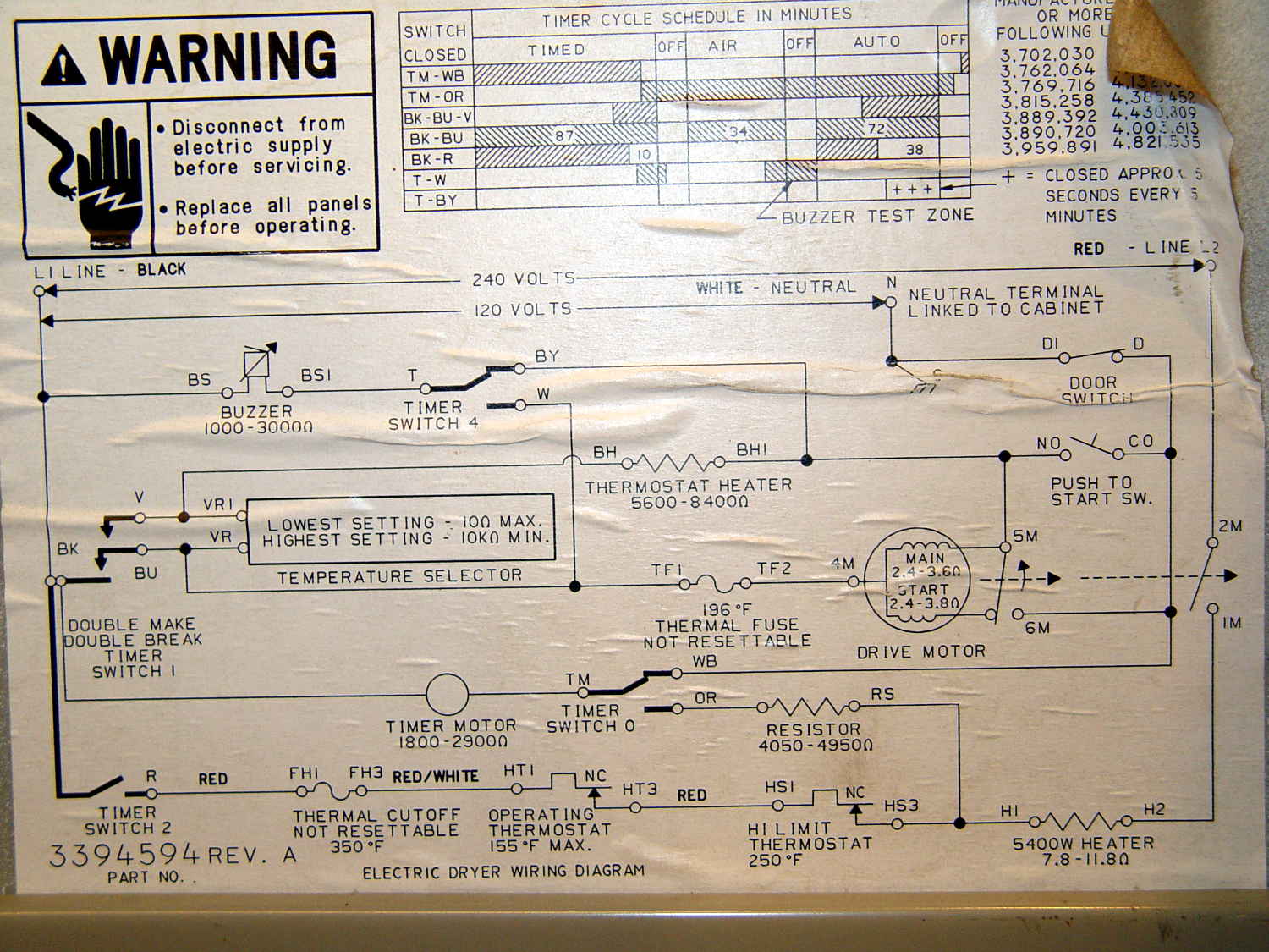
Referring to the wiring diagram may be of some help:
The timer motor is in the next-to-bottom ladder rung. Its BK terminal on the left connects to one side of the 240 VAC supply and the switch just to its right connects terminal TM to either the neutral AC line (thus unbalancing the 240 VAC line by a smidge) or to through a 4-ish kΩ resistor and the heater element (essentially zero, on this scale) to the other hot line; the resistor thus dropping 120-ish VAC.
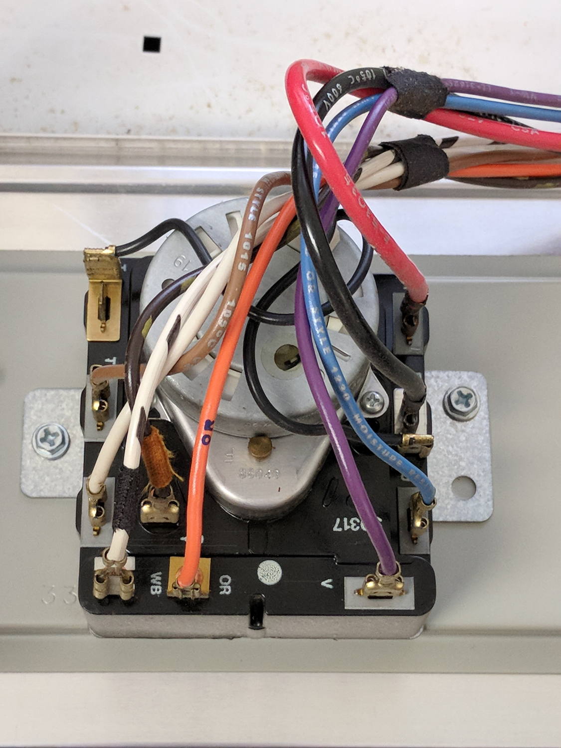
The various switches around the timer collect nearly all the wiring in the dryer:
Kenmore dryer – timer wiring
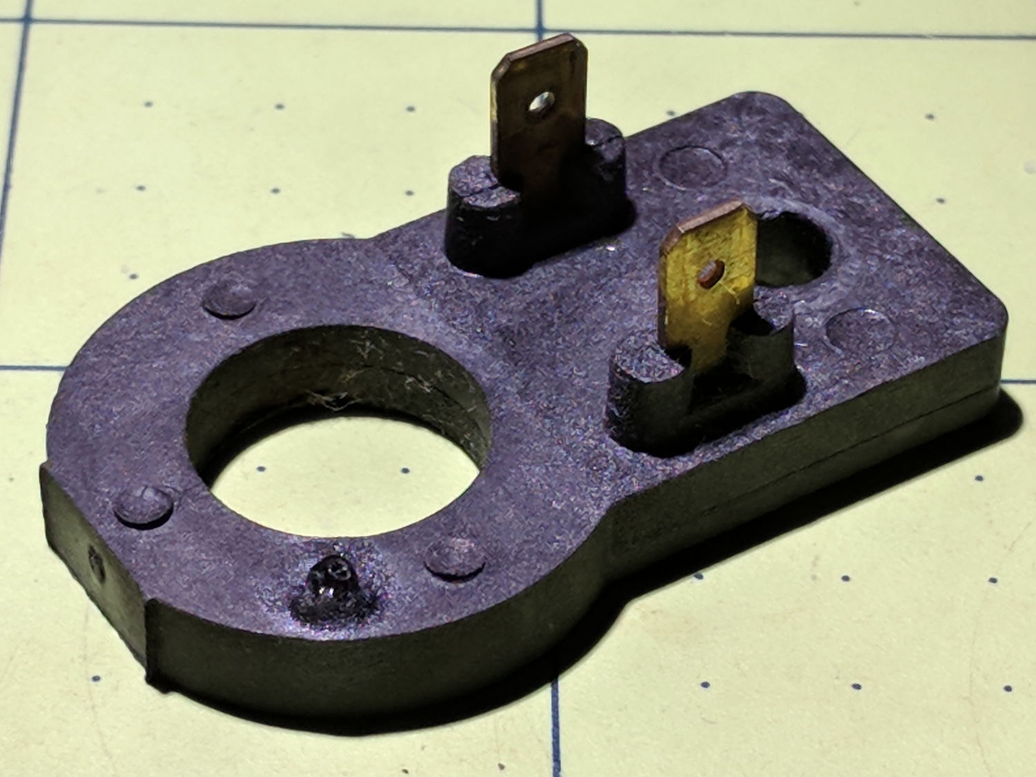
A closer look at the back, minus all the wiring:
Kenmore dryer – timer backplate
The motor comes off easily enough, revealing the fact that it’s not just an ordinary (i.e., cheap & readily available) timer motor:
Kenmore dryer – timer motor pinions
Hotwiring the motor through a widowmaker zip cord showed it worked just fine. For reference, the upper pinion rotates at about 45 sec/rev, the lower pinion takes maybe 1 hr/rev, both counterclockwise.
Reassembling and hotwiring the complete timer showed it worked just fine, too.
Poring over the wiring diagram suggested the power resistor might be open and, indeed, it was:
Kenmore dryer – power resistor failure
The raised zit near the front shouldn’t be there:
Kenmore dryer – power resistor failure – detail
Apparently, the resistive element broke at that spot, burned through the thermoset plastic case, and failed safe.
Introducing it to Mr Disk Sander revealed a cavity below the zit, surrounded by the remains of the resistive element:
Kenmore dryer – power resistor – cut open
You can get a replacement resistor from the usual suspects for prices between $20 and $40, plus or minus shipping, but their pictures look a lot like an ordinary power resistor inside a length of heatshrink tubing, rather than the molded OEM part. I don’t put much stock in reviews & comments, although they seemed to suggest you get, indeed, an ordinary power resistor.
I didn’t have a 4.7 kΩ power resistor in my (diminished) collection, so I soldered a giant 1.5 kΩ cylindrical resistor in series with a small 3.5 kΩ sandbox, wrapped them up, and tucked them under the front panel’s ground wire:
Kenmore dryer – expedient power resistor
A small box of resistors should arrive in the next month and I’ll re-do the repair with a bit more attention to permanency.
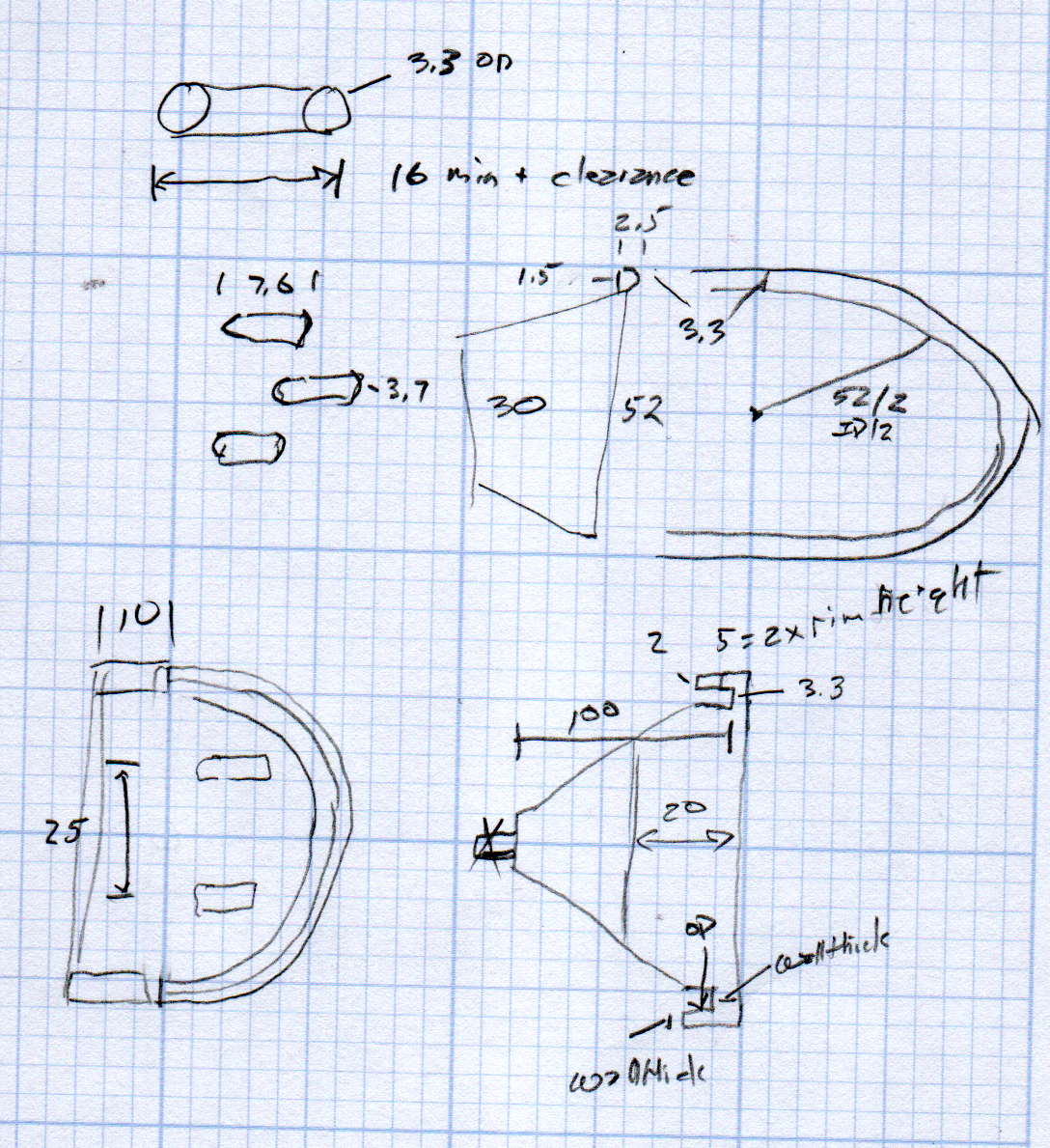
We just scrapped out the old dish drainer, only to find the gadget bin on the new drainer let the measuring spoons fall over and lie along its bottom. After a week of fishing them out from under paring knives, cheese slicers, and suchlike, I gimmicked up a holder:
Measuring Spoon Drainer – installed
One might suggest natural PETG, rather than orange, thereby displaying a shocking ignorance of the MVP concept. We’ll run with orange for the shakedown trials, then build-measure-learn, iterate, and, for all I know, we may even pivot.
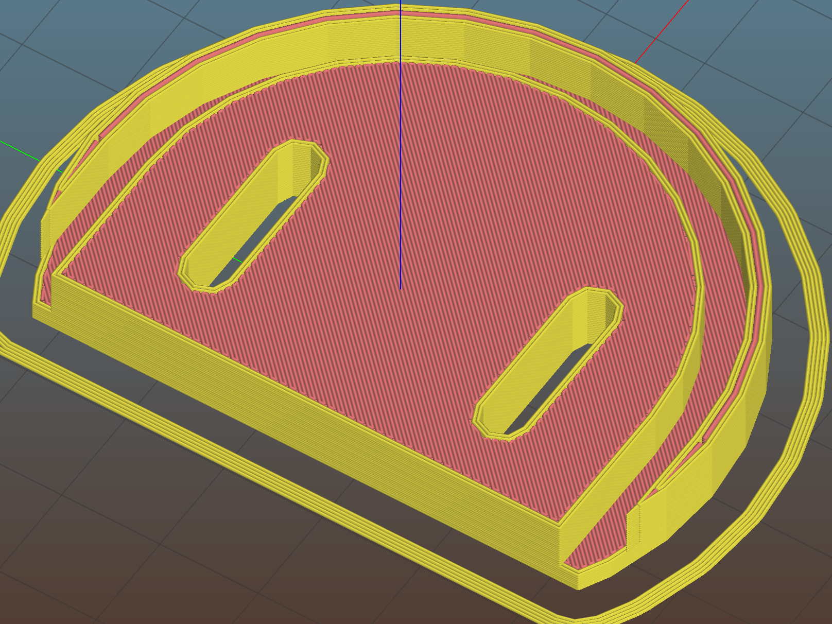
A bottom-up view of the solid model shows the trench accommodating the bin lip:
This file contains hidden or bidirectional Unicode text that may be interpreted or compiled differently than what appears below. To review, open the file in an editor that reveals hidden Unicode characters.
Learn more about bidirectional Unicode characters
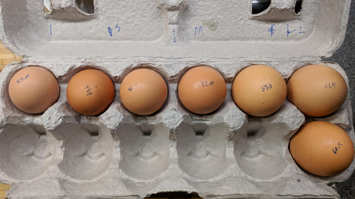
We got several cartons of “medium” brown eggs with what seemed like an unusually wide size distribution, so I picked out and weighed an assortment for future reference:
We occasionally get huge eggs, tiny eggs, eggs with two yolks, no yolks, or blood-spotted yolks, all of which turn out to be no big deal. I admit to not previously encountering the term “fart egg”, however …
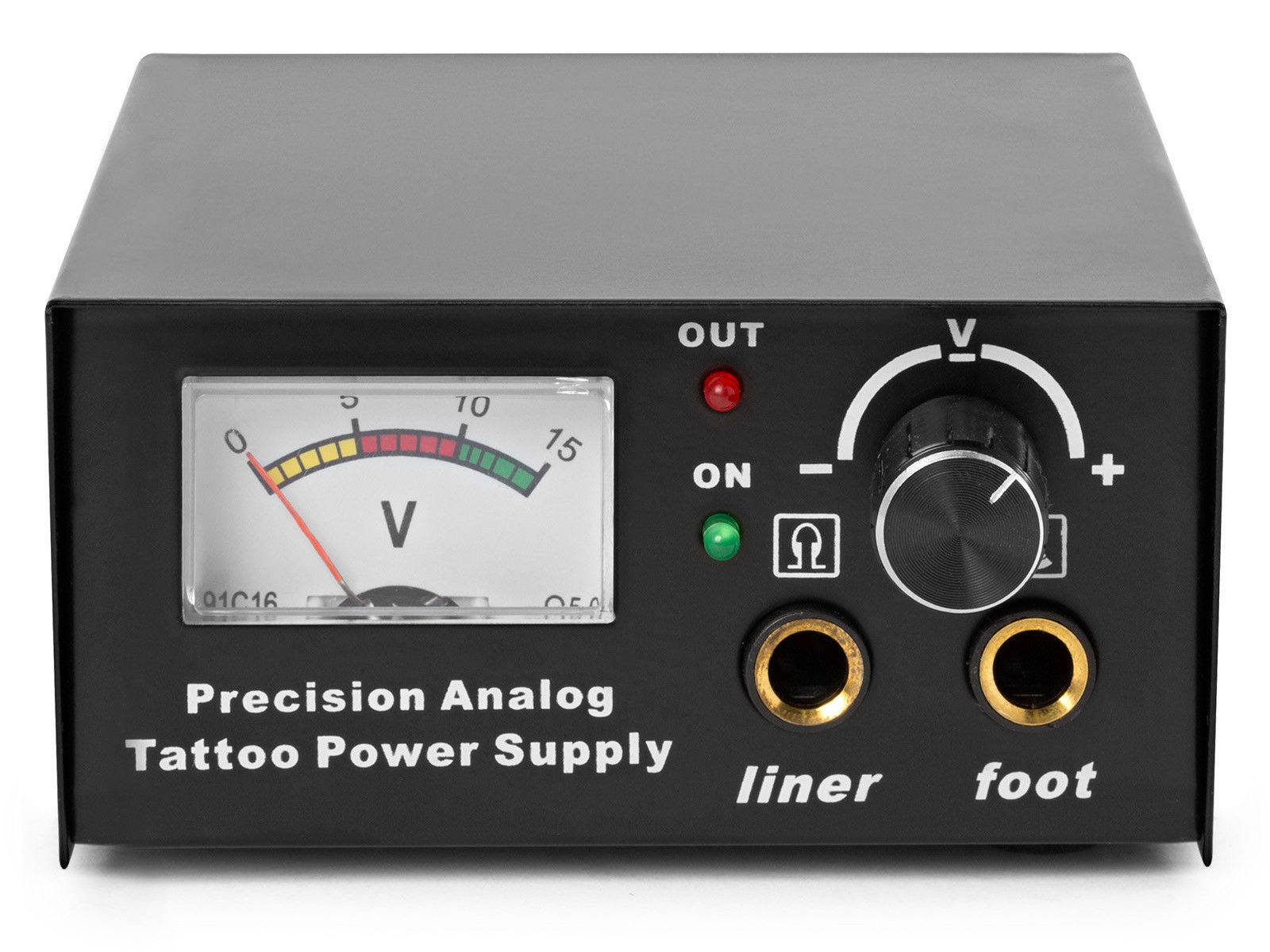
The idea behind this gadget surfaced while I was looking for something else and, although the front panel makes my skin crawl, it’s just an adjustable DC power supply:
Let’s say it has the potential to be a DC power supply, although we might quibble about the “Precision” part.
As delivered, it’s a deathtrap. Of course, it’s not UL listed and I didn’t expect it to be.
How many lethal problems do you see?
Tattoo power supply – original AC wiring
For starters, it has a three-wire AC line cord with the green-and-yellow conductor chopped off flush with the outer insulation inside the heatshrink tubing just behind the transformer:
Tattoo power supply – ungrounded AC line
The blue wire is AC neutral, but it really shouldn’t be connected to the finger-reachable outer fuse terminal.
The brown wire is AC line, which goes directly to one power switch terminal. In the event of a hot wiring fault, an unfused conductor touching the case will test the GFI you should have on your bench wiring.
The AC line cord uses some mysterious copper-colored metallic substance that’s about as stiff as music wire:
Tattoo power supply – stiff AC wire
The strands cannot be twisted together like ordinary copper wire, although they can be soldered. They may be copper-plated aluminum, because a magnet ignores them.
After soldering the strands together, they snap when bent:
Tattoo power supply – soldered broken AC wire
Generous strain relief is not just a good idea, it’s mandatory.
After some Quality Shop Time, the ground wire now connects to the case through the transformer’s rear mounting screw, the neutral AC wire connects to the transformer, the hot AC wire goes to the tip of the line fuse, and the fuse cap terminal goes to the switch:
Tattoo power supply – AC line rewiring
I relocated the white LED to the middle of the meter, where it looks a bit less weird:
Tattoo power supply – revised front panel
I have no idea what “Porket indicate” might mean. Perhaps “Precision indicator”?
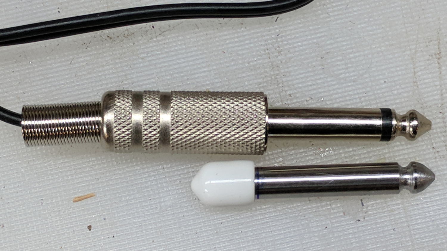
The right 1/4 inch jack, labeled “Foot”, normally goes to a foot switch you don’t need for a bench power supply, so I converted a length of drill rod into a dummy plug to short the jack contacts:
Tattoo power supply – dummy switch plug
The tip comes from a bit of lathe and file work and the white cap comes from a bag of wire shelf hardware.
A genuine hologram sticker (!) on the back panel proclaims “1.5 – 15 VDC 2 A”, which seemed optimistic. Some fiddling with power resistors suggests tattoo liners (I learned a new word!) don’t draw much current:
4 V @ 1 A
8 V @ 800 mA
10 V @ 600 mA
It can reach a bit over 18 V (pegging the meter) at lower current, so it’s Good Enough for small projects with un-fussy power requirements.
Although I repaired the spout a while ago, those water bottles were never satisfactory and saw very little use. A recent cabinet cleanout showed the “stainless steel” has passed beyond its best-used-by date:
Stainless steel water bottle – rust
With no regard for whether the patient would survive the operation, I peeled off its rubber foot and applied the Lesser Hammer:
Stainless steel water bottle – insulation
The “insulation” seems to be a rigid urethane-like foam disk few millimeters thick on the bottom of the interior flask, with good old air around the sides.
The bottles never worked very well and now we know why.
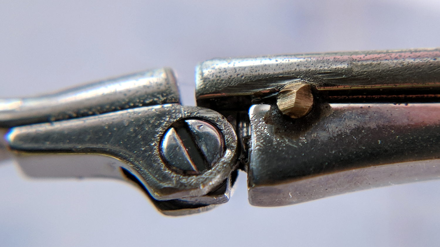
After three years, the temple screw on Mary’s oldest and most-battered “reading” glasses worked loose. A dab of low-strength Loctite should hold it in place forever more:
Reading glasses temple repair
That brass stake pin certainly adds a Steampunk flair to the proceedings …