Ed Nisley's Blog: Shop notes, electronics, firmware, machinery, 3D printing, laser cuttery, and curiosities. Contents: 100% human thinking, 0% AI slop.
We’ve been using it daily ever since and it spends most of its life drip-drying in the dish drainer. I added a third opening to the cheerful orange measuring spoon holder just for the slicer.
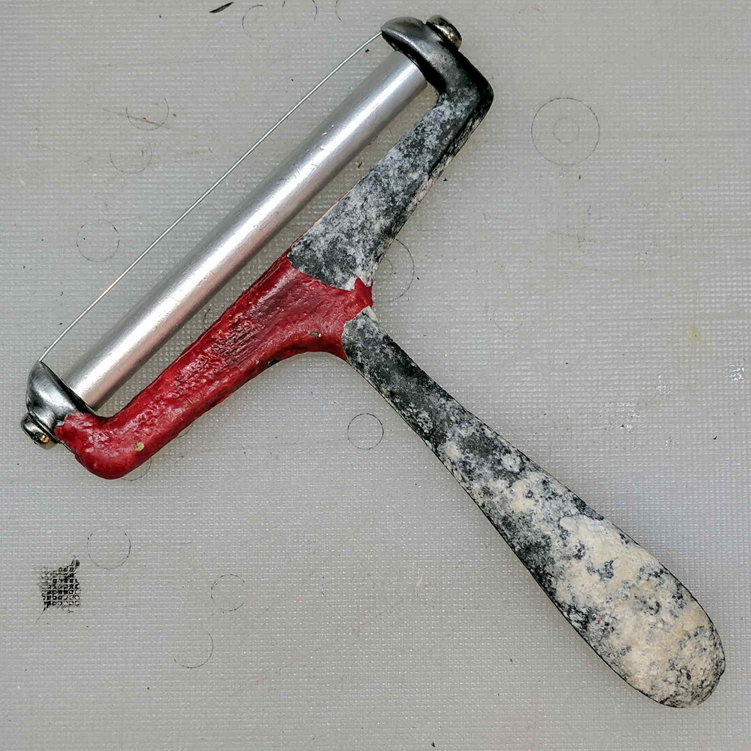
A few weeks ago I noticed corrosion once again growing on the handle:
Cheese Slicer – epoxy coat – corrosion – detail
I think the rot comes from water diffusing through the epoxy, rather than gross leaks through damage or pinholes. The tip of the handle has the most corrosion, probably due to the water drop hanging there, even though it also has the thickest epoxy coating: it cured with the handle pointing downward.
A long time ago, a pair of white LED + red laser flashlights powered by an AA cell diverged: one flashlight worked fine, the other always had a dead battery. The latter ended up on my “one of these days” pile, from which it recently emerged and accompanied me to a Squidwrench Tuesday session:
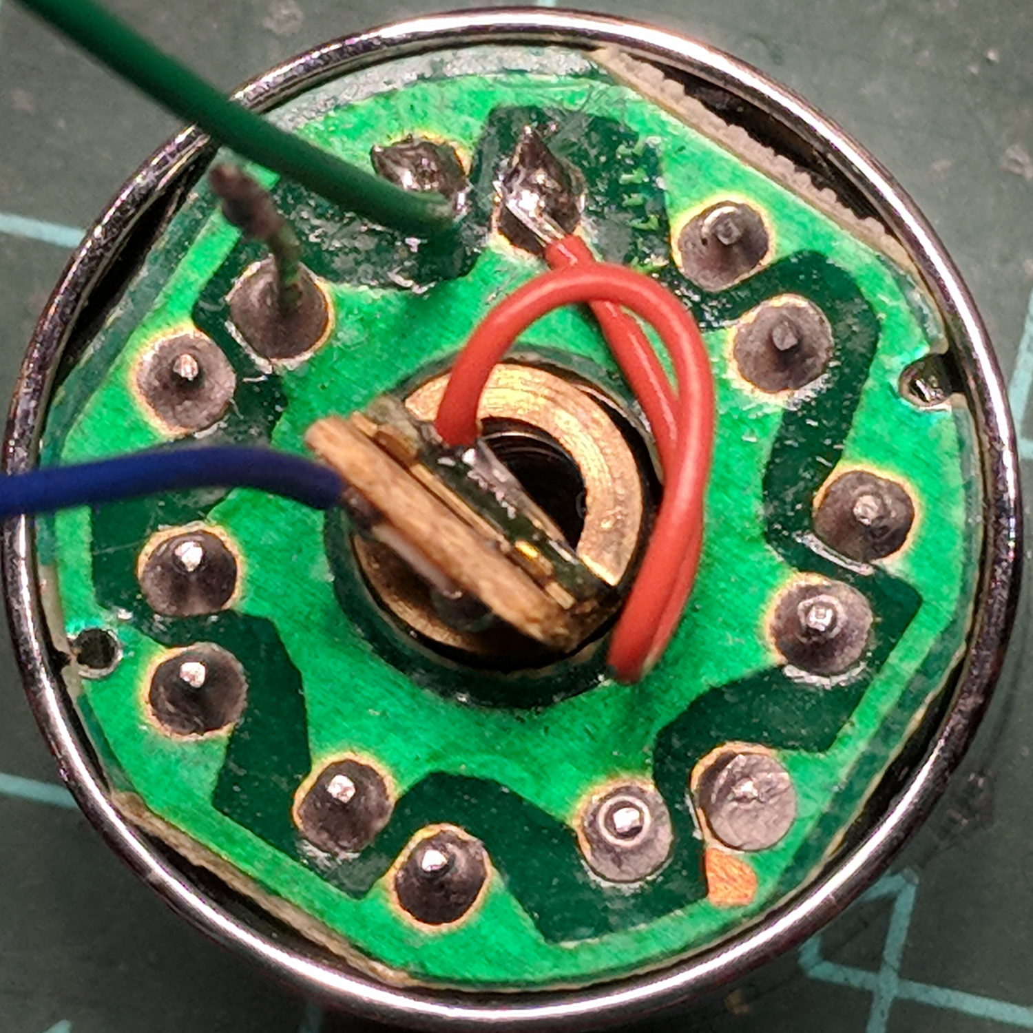
Small Sun flashlight – original wiring
The black wire trailing from the innards goes to the battery negative terminal, with the aluminum body providing the positive terminal connection to the wavy-washer spring contact visible atop the rear PCB inside the front shell.
The switch connects each red wire to the battery negative terminal, so there’s a color code issue in full effect. The two red wires burrow through holes in the rear PCB (shown above) and connect to the negative terminal of the laser module (the brass cylinder near the top) and the negative terminal ring on the front PCB holding the seven white LEDs:
Small Sun flashlight – original wiring – LED laser board
Continuing the color code issue, the black wire from the laser is its positive terminal. The out-of-focus wire (an LED pin) sticking up near the top of the picture carries the positive connection to the LED ring. The red wires from the switch are the negative connections for the LEDs and laser.
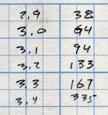
Voltages applied to the LED ring and the currents flowing therein:
Small Sun flashlight – 7x white LED current vs voltage
Seven LEDs at 20 mA each = 140 mA, so the voltage booster must crank out slightly more than 3.2 V. They’re not the brightest white LEDs I’ve ever seen, but suffice for a small flashlight.
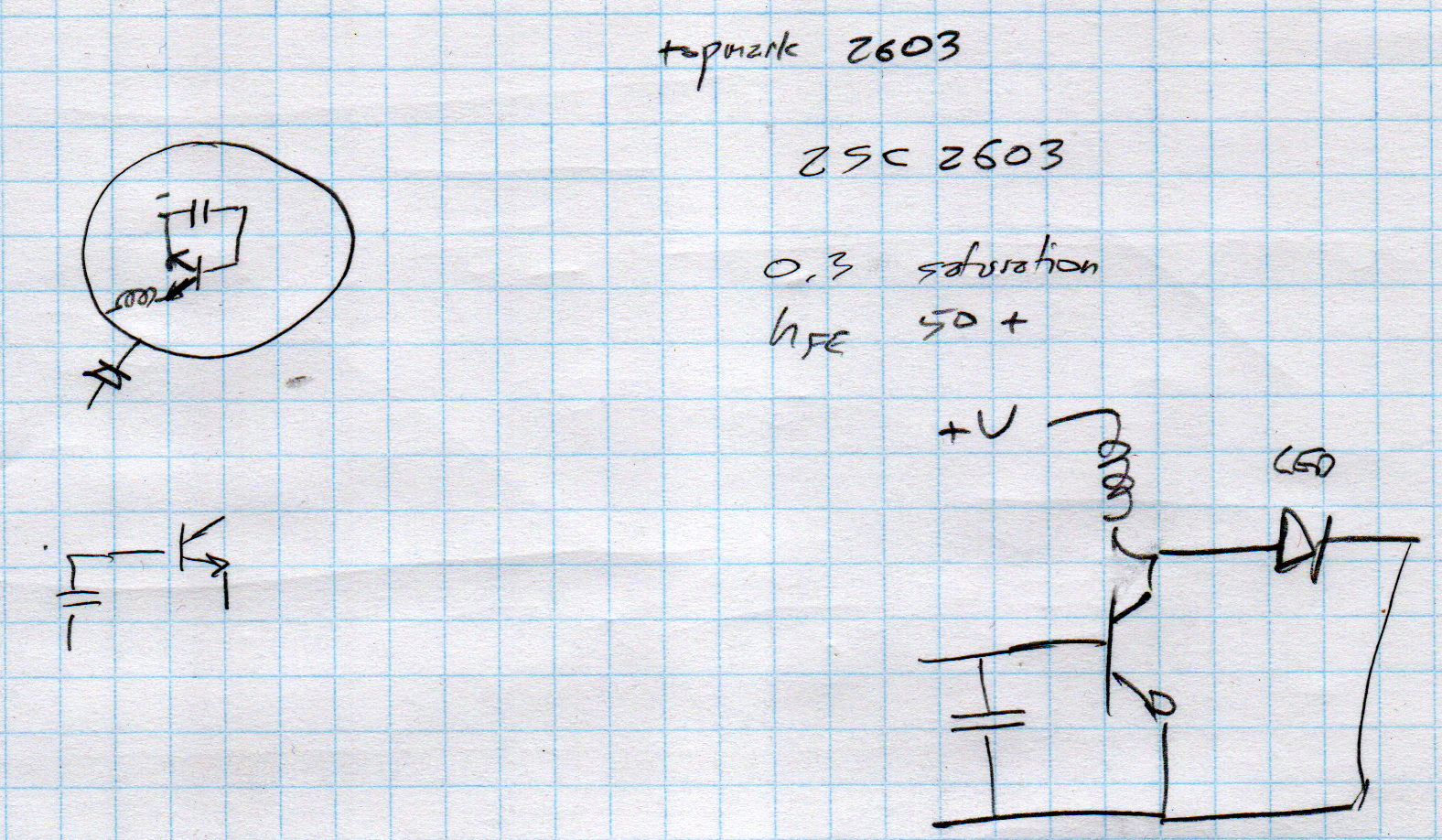
A crude sketch of the PCB layout, with a completely incorrect schematic based on the mistaken assumption the SOT23-3 package was an NPN transistor:
Small Sun flashlight – schematic doodle
Obviously, that’s just not ever going to oscillate, even if the 2603 topmark meant a 2SC2603 transistor, which it doesn’t.
A bit more searching suggests it’s a stripped-down Semtech SC2603A boost converter, normally presented in a SOT23-6 package. If you order a few million of ’em, you can strip off three unused pins, do some internal rebonding, and (presumably) come out with an SOT23-3:
Small Sun flashlight – correct schematic doodle
That topology makes more sense!
Before going further, I had to rationalize the colors:
Small Sun flashlight – rewired LED laser board
Soldering longer leads to the PCB allows current & voltage measurements:
Small Sun flashlight – LED current test
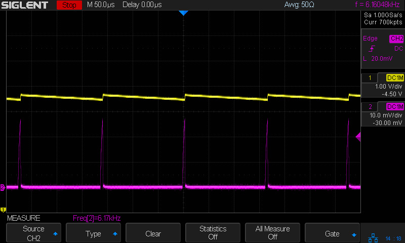
With the LEDs and laser disconnected, the converter seems to be struggling to keep the capacitor charged:
Small Sun flashlight – V boost I 200mA-div – idle
Those purple spikes come from the current probe at 200 mA/div: maybe half an amp in 5 μs pulses at 6 kHz works out to a 15 mA average current, which is pretty close to the 11 mA I measured; it’s not obvious the Siglent SDM3045 meter was intended to handle such a tiny duty cycle.
Obviously, the output capacitor is junk and, after removing it, the AADE L/C meter says NOT A CAPACITOR. Perhaps it never was one?
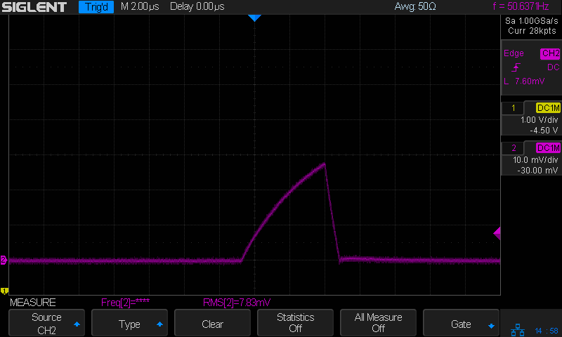
Measuring the cap in the good (well, the other flashlight) suggests something around 100 nF, so I installed a random 110 nF cap from the stash. The current peaks are about the same size:
Small Sun flashlight – I 200mA-div – 110nF cap
The cap voltage (not shown) is now nearly constant and the 50 Hz PWM rate reduces the average battery current to 100-ish μA:
Small Sun flashlight – I 200mA-div – color-grade – 110nF cap
Not great, but tolerable; a 1000 mA·h battery will go flat in a few months.
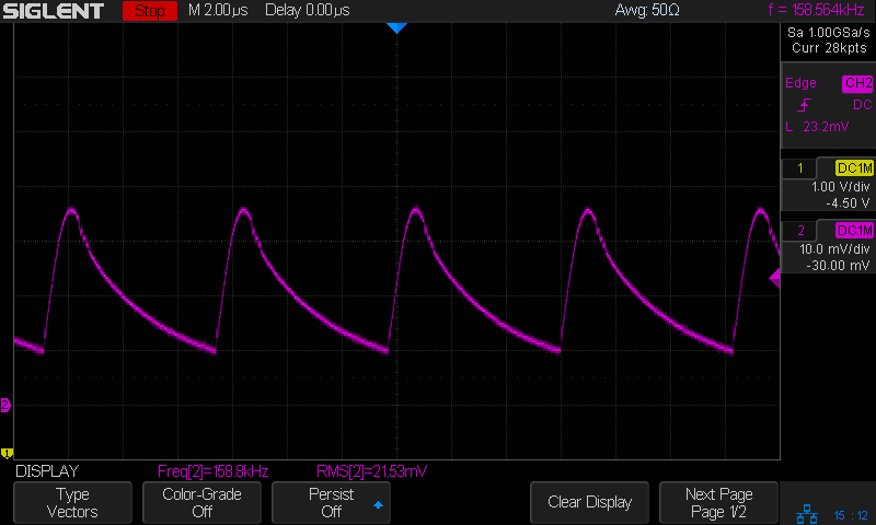
The LED current runs a bit hotter than I expected:
Small Sun flashlight – I 200mA-div – LED current – 110nF cap
The bottom is about 200 mA and the average might be 350 to 400 mA.
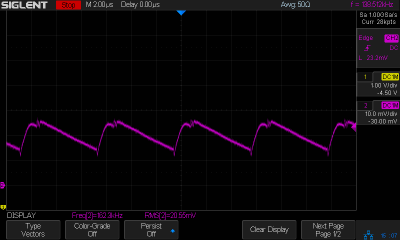
Compared with the other flashlight:
Small Sun flashlight other – I 200mA-div – LED current
So the cap is maybe a bit too small, but it likely doesn’t matter.
What looks like a blob on the left side covers the missing chip, with the rest of the ring filled in to make it look like I knew what I was doing. The drain dried out while we were on vacation, having been scrubbed clean before we left, making for the best surface preparation I could provide.
As it turns out, our resident iron bacteria took about a week to set up shop along the bottom of the ring, producing a pair of small rust-colored dots that will inevitably spread to encompass the whole thing. They’re endemic in the plumbing, impossible to kill off, and nothing more than an unsightly nuisance.
A soaker hose leaped under a descending garden fork and accumulated a nasty gash:
Soaker Hose Splice – gashed
Mary deployed a spare and continued the mission, while I pondered how to fix such an odd shape.
For lack of anything smarter, I decided to put a form-fitting clamp around the hose, with silicone caulk buttered around the gash to (ideally) slow down any leakage:
Soaker Hose Splice – Solid Model – Assembled
As usual, some doodling got the solid model started:
Soaker Hose Splice – Dimension doodle 1
A hose formed from chopped rubber doesn’t really have consistent dimensions, so I set up the model to spit out small test pieces:
Soaker Hose Splice – Test Fit – Slic3r
Lots and lots of test pieces:
Soaker Hose Splice – test pieces
Each iteration produced a better fit, although the dimensions never really converged:
Soaker Hose Splice – Dimension doodle 2
The overall model looks about like you’d expect:
Soaker Hose Splice – Complete – Slic3r
The clamp must hold its shape around a hose carrying 100 psi (for real!) water, so I put 100 mil aluminum backing plates on either side. Were you doing this for real, you’d shape the plates with a CNC mill, but I just bandsawed them to about the right size and transfer-punched the hole positions:
Soaker Hose Splice – plate transfer punch
Some drill press action with a slightly oversize drill compensated for any misalignment and Mr Disk Sander rounded the corners to match the plastic block:
Soaker Hose Splice – plate corner rounding
A handful of stainless steel 8-32 screws holds the whole mess together:
Soaker Hose Splice – installed
These hoses spend their lives at rest under a layer of mulch, so I’m ignoring the entire problem of stress relief at those sharp block edges. We’ll see how this plays out in real life, probably next year.
I haven’t tested it under pressure, but it sure looks capable!
This file contains hidden or bidirectional Unicode text that may be interpreted or compiled differently than what appears below. To review, open the file in an editor that reveals hidden Unicode characters.
Learn more about bidirectional Unicode characters