Ed Nisley's Blog: Shop notes, electronics, firmware, machinery, 3D printing, laser cuttery, and curiosities. Contents: 100% human thinking, 0% AI slop.
I finally got around to replacing the Forester’s taillight bulbs:
Subaru Forester taillight bulbs
The clear bulbs don’t have the same thermal damage as the headlights I replaced a year ago, but the new bulbs should be much brighter.
Subaru calls them W21/5W and WY21W, respectively, but the rest of the world says 7443 and 7440NA (or 7440A).
For the record, the taillight assembly comes off (after removing the obvious pair of screws not shown here) by pulling straight back with grippy gloves:
Subaru Forester taillight mount
Aligning the locating pins with those two latching sockets (why is one green?) requires a flashlight and a bit of dexterity, but easing the slot over the white post first helps a lot. Practice makes perfect: it’s easier on the other side of the car.
A glass-top patio table came with our house and, similar to one of the patio chairs, required some repair. The arched steel legs fit into plastic brackets / sockets around the steel table rim under the glass top:
Glass patio table – new brackets installed
The four glaringly obvious white blocks are the new brackets.
The original brackets had, over uncounted years, deteriorated:
Glass patio table – failed OEM bracket
Perhaps disintegrated would be a better description:
Glass patio table – crumbled OEM bracket
Each leg has a pair of rusted 1-½ inch ¼-20 screws holding it to the central ring. As expected, seven of the eight screws came out easily enough, with the last one requiring an overnight soak in Kroil penetrating oil plus percussive persuasion:
Glass patio table – jammed screw
The four legs had three different screws holding them to the brackets, so I drilled out the holes and squished M5 rivnuts in place:
Glass patio table – M5 rivnut installed
Although it’s not obvious, the end of that tube is beveled with respect to the centerline to put both the top and bottom edges on the table rim inside the bracket. In addition, the tube angles about 10° downward from horizontal, which I did not realize amid the wrecked fittings, so the first bracket model failed instantly as I inserted the leg:
Glass patio table – first bracket test
The top & bottom walls of that poor thing were breathtakingly thin (to match the original bracket) and cracked when confronted with the angled tube. I could not measure all the sizes & angles without assembling the table on trial brackets, so getting it right required considerable rapid prototyping:
Glass patio table – failed brackets
Some trigonometry produced a solid model with features rebuilding themselves around the various sizes / angles / offsets:
Glass Top Table – leg bracket – solid model
A sectioned view shows the angled tube position and end chamfer:
Glass Top Table – leg bracket – section view
The OpenSCAD code can produce a sectioned midline slice useful for laser-cut MDF pieces to check the angle:
That eliminated several bad ideas & misconceptions, although trying to balance the leg on a 3 mm MDF snippet was trickier than I expected. In retrospect, gluing a few snippets together would be easier and still faster than trying to print a similar section from the model.
The slightly elongated slot for the M5 screw shows that the original screw holes were not precisely placed or that the tubes were not precisely cut, neither of which come as a surprise. I finally built some slop into the design to eliminate the need for four different blocks keyed to four different legs.
The outer rim, the notch on the bottom, and the tab on the top curve to match the four foot OD glass tabletop, with the inward side & ends remaining flat:
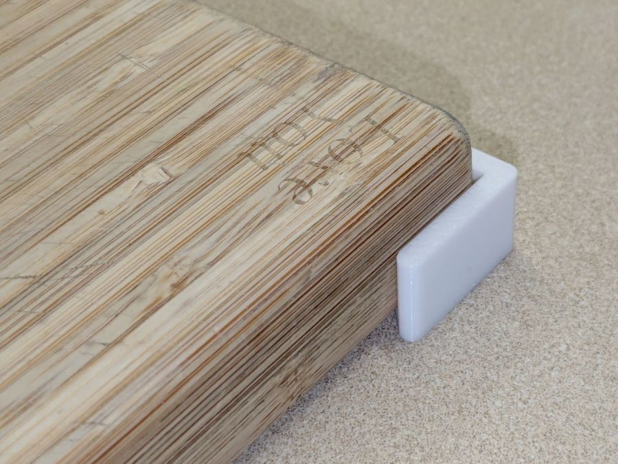
Glass patio table – chunky bracket installed – top
The sector’s difference from a straight line amounts to half a millimeter and improved the fit enough to justify the geometric exercise. The bracket snaps into position with the notch over the table rim and the tab locked in the gap between the glass disk & the rim, although I suspect the weight of the tabletop would keep everything aligned anyway.
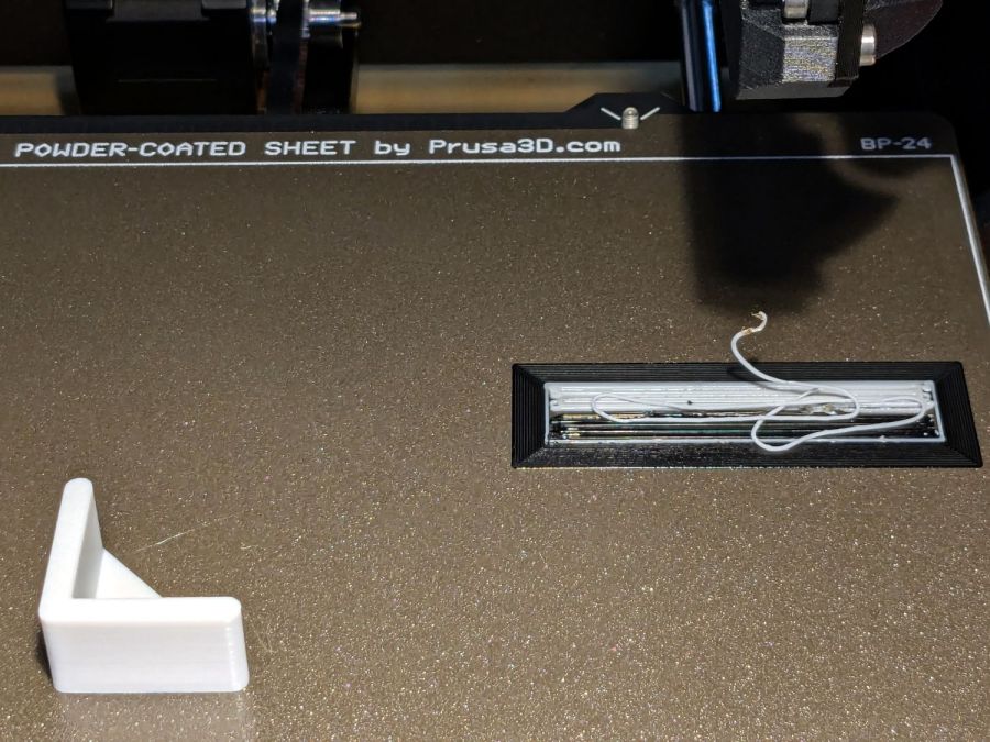
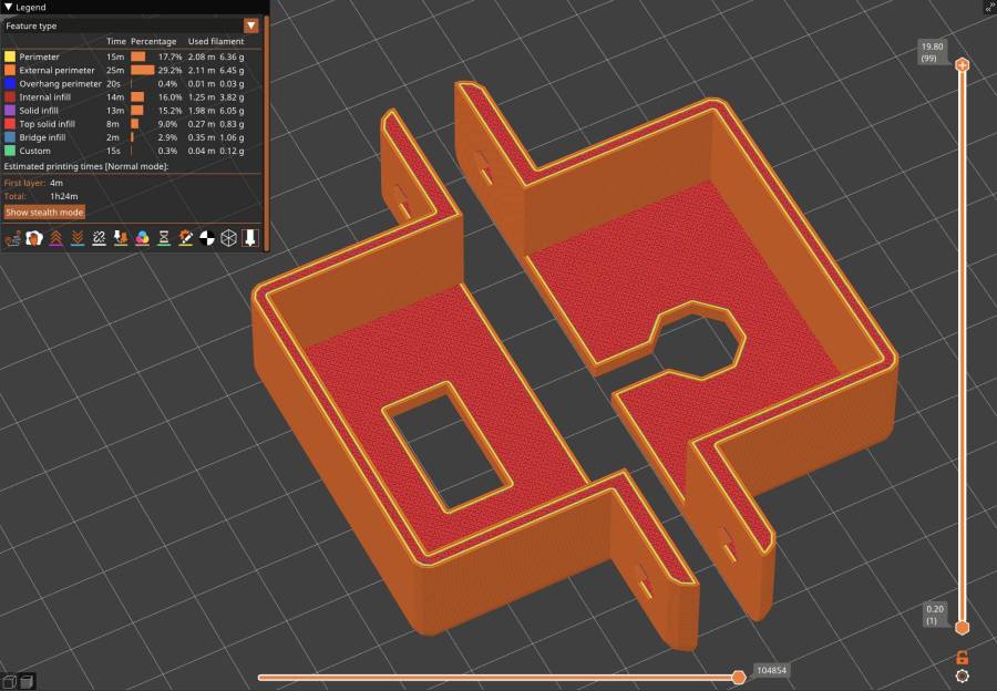
The walls are now at least 4 mm thick and, printed in PETG, came out strong enough to survive assembly and some gentle testing. They’re arranged to print on their side to eliminate support under those slight curves and to align the layers for best strength vertically in the finished bracket:
Glass Top Table – leg bracket – slicer preview
The leg cavity and screw hole built well enough without internal support.
They’re relentlessly rectangular and I’m not going to apologize one little bit.
Now to see how they survive out there on the screened porch.
Update: This post seems strangely popular, so the GitHub Gist now includes the STL file in ASCII format. Your library / makerspace / friend can print it, but it probably won’t fit your table, because all tables are slightly different. Print it in TPU and maybe it’ll flex to fit, but ideally you should use the source: install OpenSCAD, tweak the dimensions to suit your table, and get an exactly matching solid model.
This file contains hidden or bidirectional Unicode text that may be interpreted or compiled differently than what appears below. To review, open the file in an editor that reveals hidden Unicode characters.
Learn more about bidirectional Unicode characters
Attacking a plastic wheelbarrow with a ¾ inch hole saw prevents it from becoming a mosquito breeding station:
Wheelbarrow drain holes
We had been storing it tipped to one side, resulting in the wheel filling up with water, which can’t be a Good Thing.
If it must carry a load of sand, I’ll just duct-tape the holes.
One of Mary’s friend looked at, but did not order, this wheelbarrow on Amazon. Shortly thereafter, she received a wheelbarrow in two packages: the handles and a box with everything else strapped into the barrow. After a discussion with Amazon’s support / help staff, she was told to just keep it at no charge.
Over the next few weeks, she received five more wheelbarrows, each prompting a discussion and keeping them at no charge. Eventually, somebody figured out how to stop the stream.
So half a dozen gardeners now have free wheelbarrows, courtesy of a glitch in The Machine.
The upper one has a coating of clear rattlecan paint and looks much the better for it. The lower one is bare, but also suffered greatly from being folded and tucked through itself, so it started in worse condition.
Perhaps the paper will work better when stuck to metal plant label stakes, although I suspect the adhesive sheet will fail first:
Laser test paper – small plant labels
Those are random names; Mary tells me the proper label format has the Latin nomenclature on the first line.
They’re now out on the patio for observation.
For whatever it’s worth, my fascination with this paper boils down to “it’s cheaper than Trolase” for applications not requiring archival quality and duration. If it lasts Long Enough, that’ll be Good Enough.
Having recently promoted a pair of Radford Tri-Star 90 speakers to the Sewing Room, it was time to make them presentable:
Radford Tri-Star 90 speakers – taped grill
The original foam grill covering had disintegrated and left fossilized adhesive over the metal gridwork. Being not much for historic accuracy, I used double-sided duct tape (the blue barrier film peels off) and stuck some allegedly acoustic foam in place:
Radford Tri-Star 90 speakers – re-covered
The foam is a single sheet wrapped around three sides and, after some whittling, measured 19.5 inches tall and 19.25 inches wide. The width surely depends on how snugly it’s stretched, so allow a bit more and trim to fit.
Duct tape probably isn’t the right adhesive for the job, but we’ll see how long it lasts. I really did not want to use spray glue and doubted my ability to slobber liquid stickum without oopsing the cones.
The speakers sounded great back in the day and they definitely sound much better than my deflicted ears can hear now. Mary thinks they’re OK and that’s all that matters.
Starting from an SVG file set up for 3 mm material, apply the usual optimizations & tweaks to get a usable LightBurn file, then go nuts:
Spider Collection
The big one is two cross-laid layers of corrugated cardboard using up the better part of three Home Depot Large moving boxes:
Spider – LightBurn layout – 2x cardboard
That little bitty grid is the 700×500 mm laser cutter platform, so I just slap a sheet of cardboard in place, update the workspace from the camera, select the next layout, drag it over the cardboard, and Fire The Laser.
The smaller cardboard spider over on the left is built with a single cardboard layer and succumbed to the square-cube law: the legs are entirely too bendy for the weight of the body. Although it’s not obvious from the pictures, both cardboard spiders have a keel plate I added under the body to support most of their weight.
The brightly colored little spiders got a coat of rattlecan paint without any underlying primer and definitely look like that happened:
Spider Collection – detail 2
The edge-lit fluorescent green spider is sized around 2.9 mm material, the clear spider uses 2.3 mm acrylic, and the chipboard one in the background is at 1.8 mm:
Spider Collection – detail 1
The eyes are fluorescent red or green acrylic with concentric circles engraved to catch the light. They’re more effective than I expected, although they won’t look like much after dark.
We now live in a neighborhood with youngsters and Halloween this year will be so much fun …
The WordPress AI image generator caught the general idea of “cardboard spiders”:
The Samsung range has ungainly cast-iron (or some such) grates that have long since worn out / lost their original Genuine Samsung rubber bumper feet. The grates had glued-on feet that looked very much like they belonged under something else, affixed with mystery adhesive that stuck firmly in some corners and let go in others:
Samsung grate – old foot
It seems Samsung no longer sells replacement feet, which may be an indication they don’t want customer complaints, so I got a bag of nominally compatible rubber feet from the usual source and broke out the cyanoacrylate glue:
Samsung grate – new foot
The red flecks are traces of a previous generation of adhesive, with the new cyanoacrylate peeking out around the base of the new foot.
The grates have holes for the stems of the feet, so in principle they have plenty of resistance to being shoved around. In practice, tipping the grates up to clean underneath them dislodged the feet with depressing regularity. The grates are too heavy and too awkward to remove and plunk somewhere else, which suggests this sort of range is better suited to a kitchen that’s never used or, perhaps, comes equipped with a support staff.
You’re supposed to use high-temperature adhesive and, in fact, the red flecks look remarkably like high-temp silicone gasket compound, but all the missing feet were along the back of the grates where the small & simmer burners live, so I figured cyanoacrylate was certainly worth a try.
When & if they fall out, I’ll know when they went in.