Mary wants more light directly around the needle of her Kenmore Model 158 sewing machine, as the existing light (a 120 V 15 W incandescent bulb tucked inside the end housing) casts more of a diffuse glow than a directed beam:
The end cap fits snugly around the bulb, but I thought a pair of 10 mm white LEDs, mounted side-by-side and aimed downward at the cover plate, would work. Of course, plugging a pair of white LEDs into a 120 VAC socket won’t work, but some judicious rewiring and a new 12 V DC wall wart will take care of that.
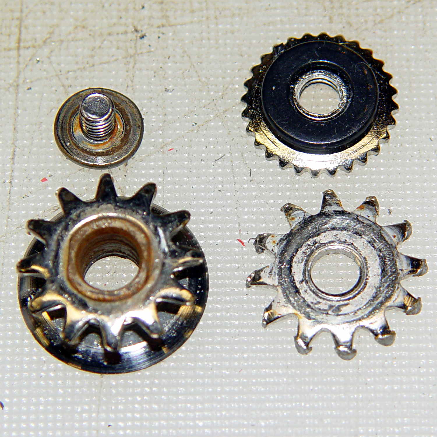
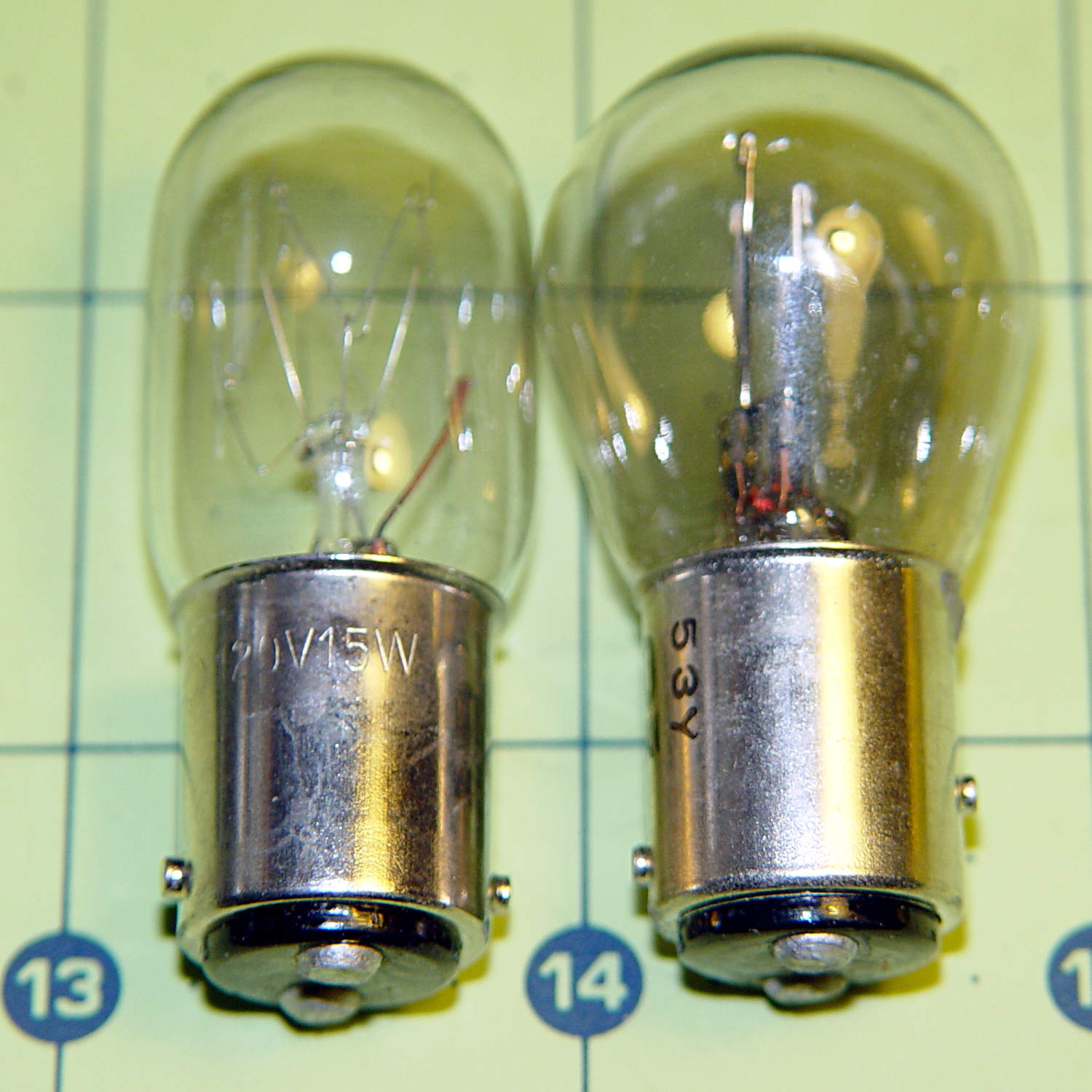
The bulb has a dual-contact bayonet base, with both pins isolated from the shell and connected to the non-polarized (!) line cord through the power switch. I didn’t know it was called a BA15d base, but now I do.
A 12 V automotive brake/taillight bulb (type 1157, I think) pulled from the Big Box o’ Bulbs has a slightly different pin arrangement that keys the filaments (which are not isolated from the shell) to the surrounding reflector:
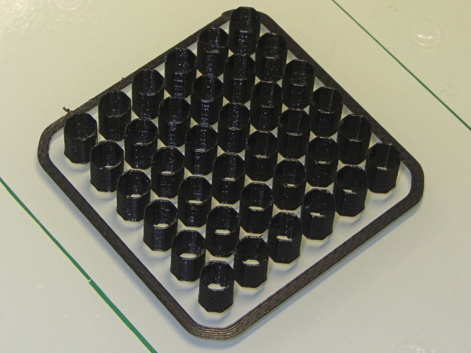
So I conjured a mockup to see if it would fit, using 2-56 screws to mimic whatever hardware might be practical:

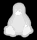
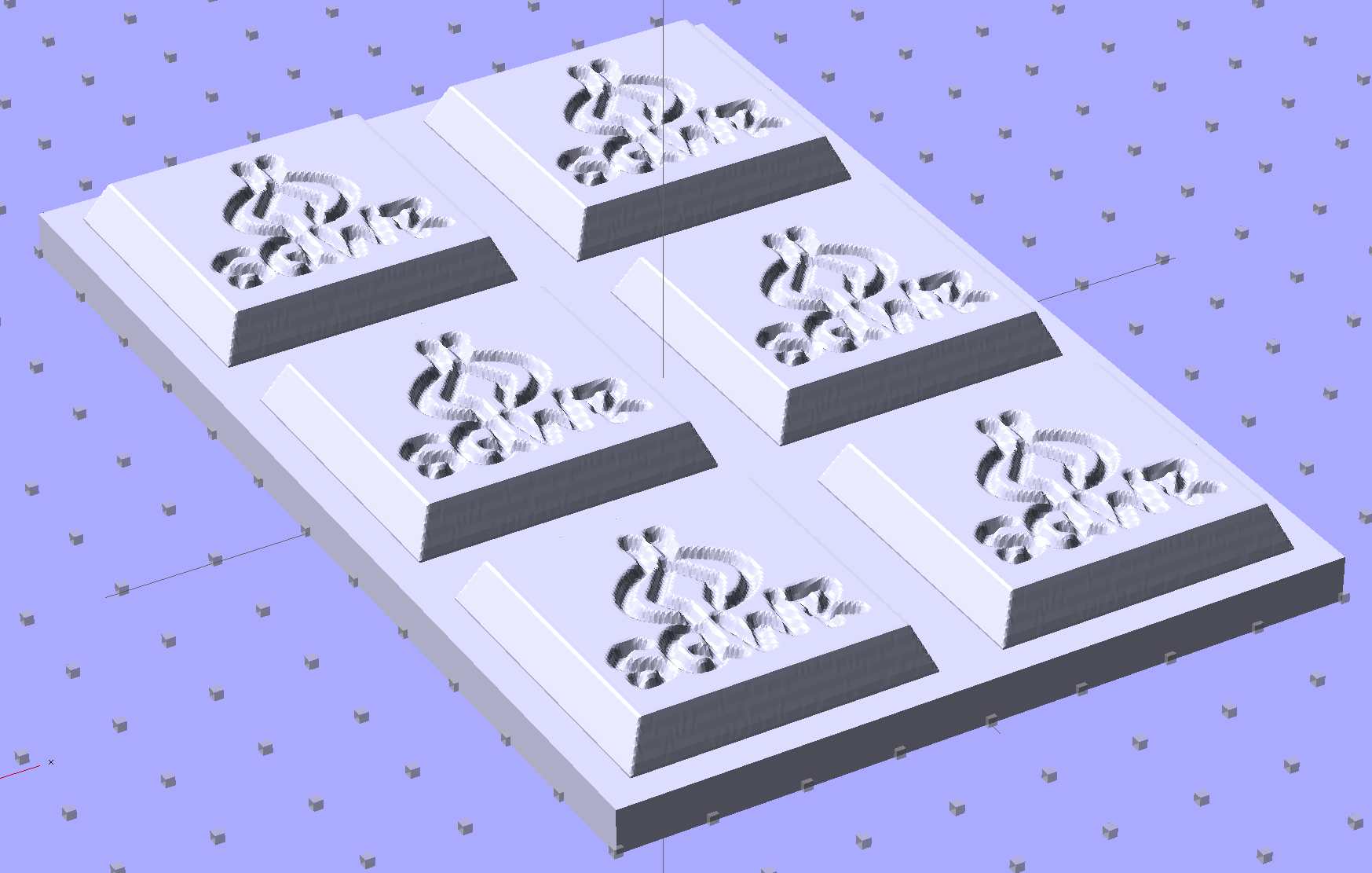
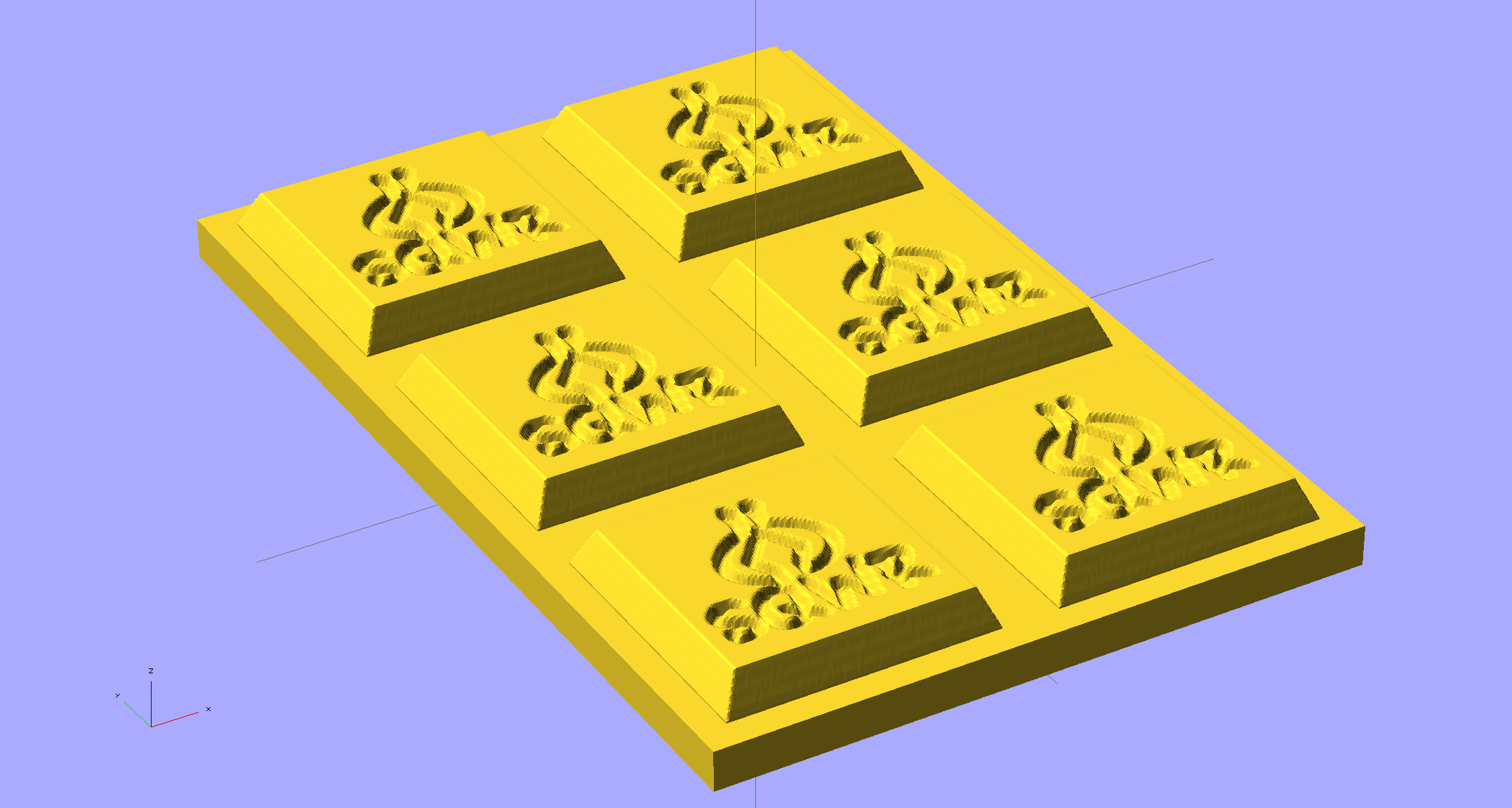
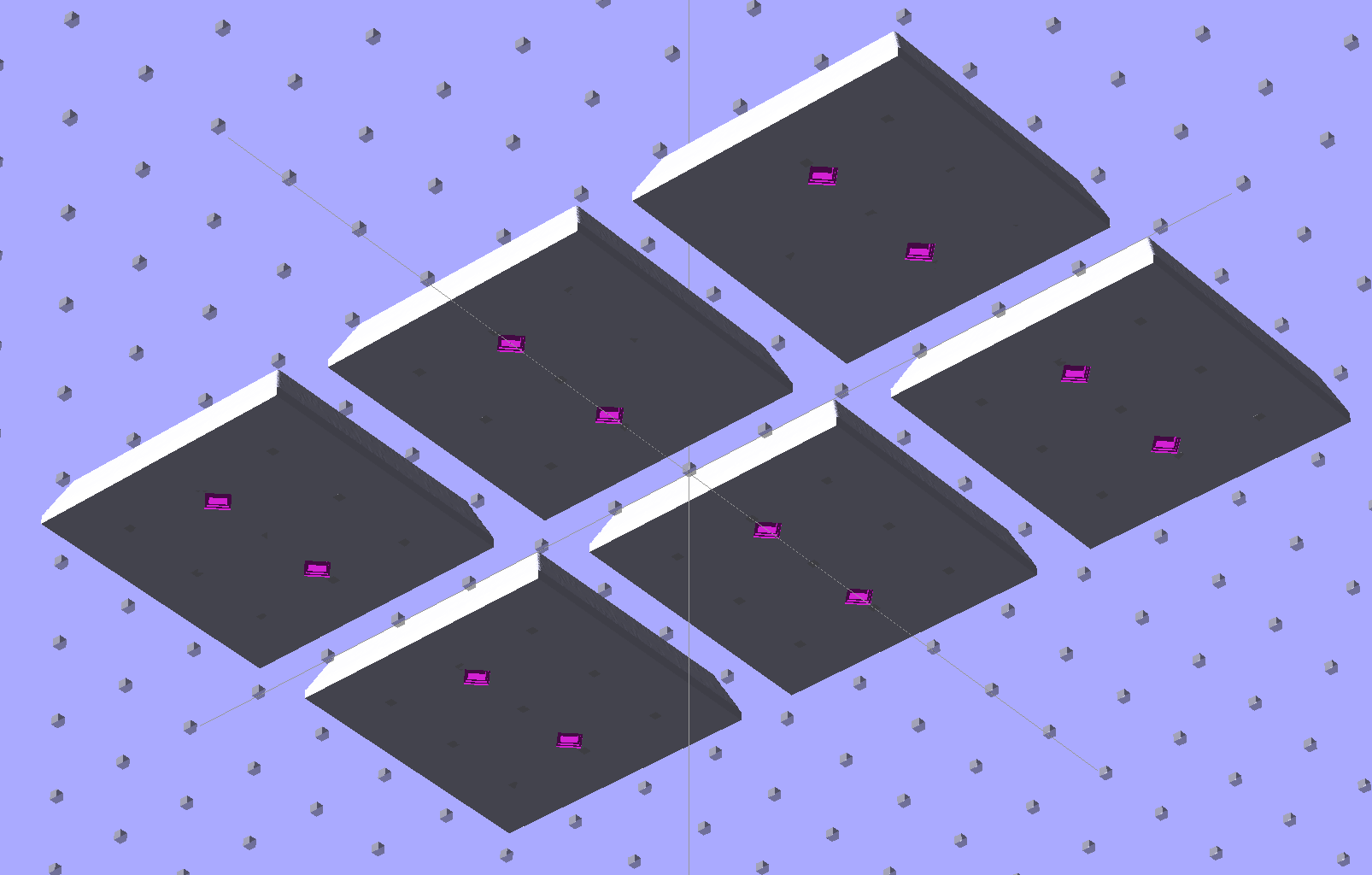
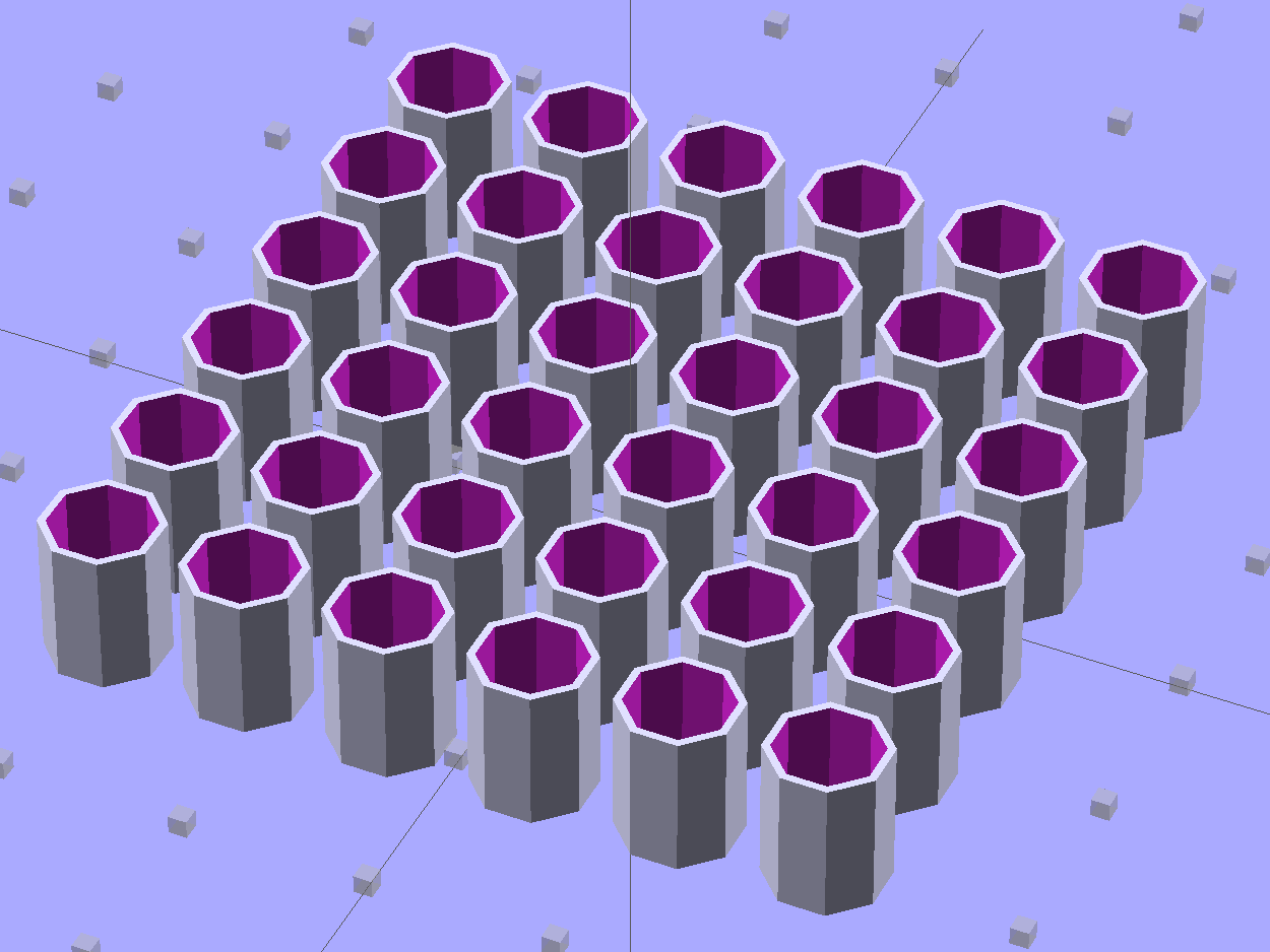
The solid model shows how it all fits together:

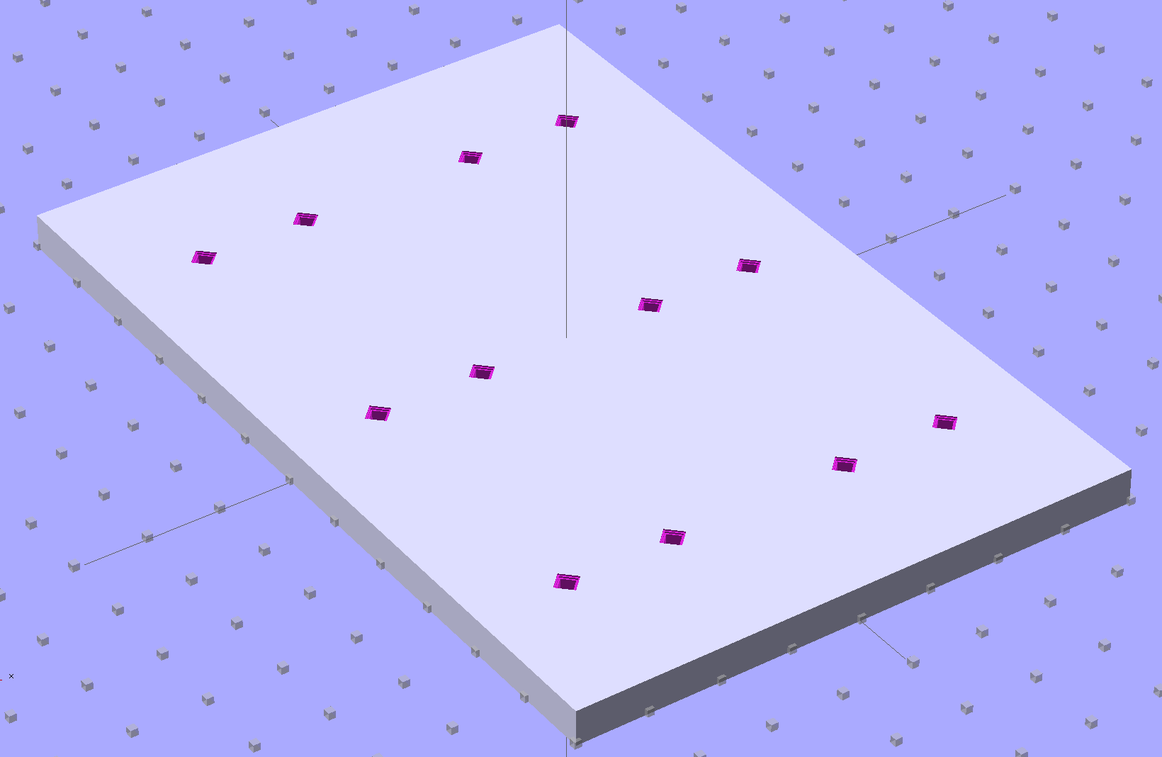
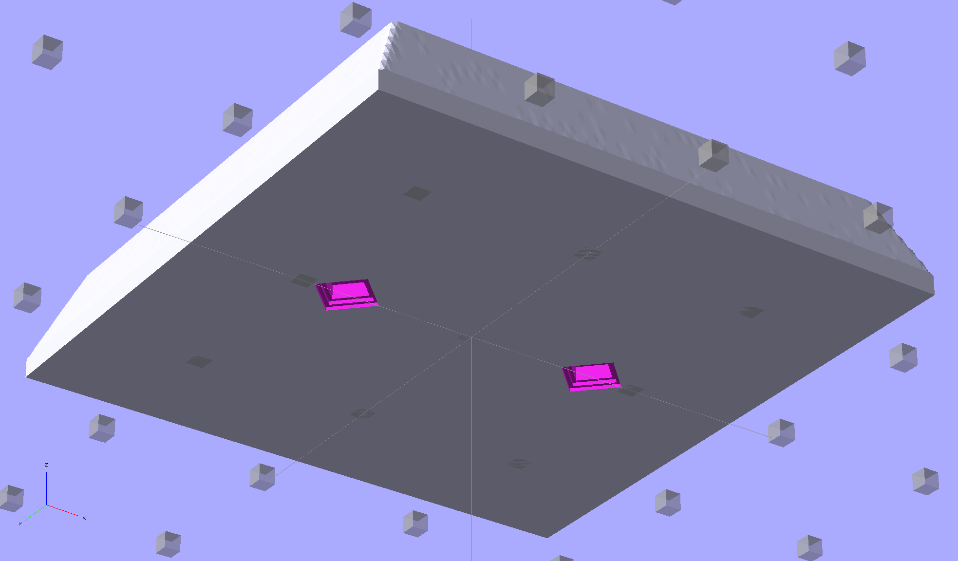
The two tiny ruby-red pins represent filament snippets in alignment holes, barely visible in real life:

I glued those pieces together, using a tiny machinist’s square as a jig to keep them perpendicular:

Some random 10 mm LEDs served for testing:

It actually fit pretty well, ignoring the fact that the LEDs point 90° from the intended direction (so I could see how the holes came out inside the pivot, honest), and lit up the area quite well, but it’s such a delicate affair that removing the entire socket and replacing it with a dedicated metal bracket / heatsink for two high-power SMD LEDs will be better.
The OpenSCAD source code:
// Adapter for LEDs in Sears sewing machine lamp socket
// Ed Nisley - KE4ZNU - January 2014

Layout = "Show";		// Build Show LEDTab LEDPlate ShellMount

//- Extrusion parameters must match reality!
//  Print with 2 shells and 3 solid layers

ThreadThick = 0.20;
ThreadWidth = 0.40;

HoleWindage = 0.2;			// extra clearance

Protrusion = 0.1;			// make holes end cleanly
Gap = 2.0;					// spacing between Show parts

AlignPinOD = 1.70;			// assembly alignment pins: filament dia

inch = 25.4;

//----------------------
// Dimensions

//-- LED mounting plate

LEDDia = 10.0;				// LED case OD
LEDFlangeOD = 10.7;

LEDPlateThick = 2.0;		// mounting plate thickness
LEDMargin = 2.0;

LEDSpaceOC = LEDDia + LEDMargin;		// LED center-to-center distance (single margin between!)

LEDTabLength = 15.0;		// base to screw hole center

LEDTabThick = 4.0;			// tab with hole for mounting screw
LEDTabScrewOD = 2.0;
LEDTabWidth = (3.0*2) + LEDTabScrewOD;

LEDMountHeight = 25.0;		// estimated mounting screw centerline to bottom of LEDs

//-- Lamp base adapter
//		hard inch dimensions!

ShellOD = 0.600 * inch;				// dia of metallic shell
ShellOAL = 0.66 * inch;				//  ... total length
ShellInsert = 7/16 * inch;			//  ... length engaging socket

ShellSides = 4*4;

BulbOD = 0.75 * inch;				// glass bulb
BulbLength = 1.14 * inch;

InsulOD = 0.485 * inch;				// insulating stub around contact pins
InsulThick = 0.070 * inch;			//  ... beyond end of shell

ContactOD = 2.0;					// contact holes through base (not heads)
ContactOC = 0.300 * inch;			//  ... center-to-center spacing

BayonetOD = 0.080 * inch;			// bayonet pin diameter
BayonetOffset = 0.125 * inch;		// from end of metal base

LampOAL = InsulThick + ShellOAL + BulbLength;
echo(str("Overall Length: ",LampOAL));

//-- Miscellany

//----------------------
// Useful routines

module PolyCyl(Dia,Height,ForceSides=0) {			// based on nophead's polyholes

  Sides = (ForceSides != 0) ? ForceSides : (ceil(Dia) + 2);

  FixDia = Dia / cos(180/Sides);

  cylinder(r=(FixDia + HoleWindage)/2,
           h=Height,
           $fn=Sides);
}

module ShowPegGrid(Space = 10.0,Size = 1.0) {

  Range = floor(50 / Space);

	for (x=[-Range:Range])
	  for (y=[-Range:Range])
		translate([x*Space,y*Space,Size/2])
		  %cube(Size,center=true);
}

//-- Tab for screw mounting LED holder
//		AddLength remains below Z=0 for good union

module LEDTab() {

	difference() {
		linear_extrude(height=LEDTabThick)
			hull() {
				circle(d=LEDTabWidth);
				translate([LEDTabLength/2,0,0])
					square([LEDTabLength,LEDTabWidth],center=true);
			}
		translate([0,0,-Protrusion])
			rotate(180/6)
				PolyCyl(LEDTabScrewOD,(LEDTabThick + 2*Protrusion),6);
		for (i=[-1,1])
			translate([LEDTabLength/2,i*LEDTabWidth/4,LEDTabThick/2])
				rotate([0,90,0]) rotate(180/4)
					PolyCyl(AlignPinOD,(LEDTabLength/2 + Protrusion),4);
	}
}

//-- Plate holding LEDs

module LEDPlate() {

	difference() {
		union() {
			linear_extrude(height=LEDPlateThick)
				hull() {
					for (i=[-1,1])
						translate([i*LEDSpaceOC/2,0,0])
							circle(d=(LEDDia + 2*LEDMargin));
					translate([0,(LEDFlangeOD/2 + LEDTabWidth/2),0])
						square([LEDTabThick,LEDTabWidth],center=true);
				}
		}
		for (i=[-1,1])
			translate([i*LEDSpaceOC/2,0,-Protrusion])
				rotate(180/12)
					PolyCyl(LEDDia,(LEDPlateThick + 2*Protrusion),12);
		for (i=[-1,1])
			translate([0,(i*LEDTabWidth/4 + LEDFlangeOD/2 + LEDTabWidth/2),3*ThreadThick]) rotate(180/4)
				PolyCyl(AlignPinOD,(LEDTabLength/2 + Protrusion),4);

	}
}

//-- Bulb shell mounting adapter

module ShellMount() {

	difference() {
		union() {
			cylinder(r1=InsulOD/2,r2=ShellOD/2,h=(InsulThick + Protrusion),$fn=ShellSides);
			translate([0,0,InsulThick])
				cylinder(r=ShellOD/2,h=(LampOAL - LEDMountHeight + LEDTabWidth/2),$fn=ShellSides);
		}

		translate([0,ShellOD,(InsulThick + BayonetOffset)])		// bayonet pin hole
			rotate([90,0,0]) rotate(180/4)
				PolyCyl(BayonetOD,2*ShellOD,4);

		translate([0,ShellOD,(InsulThick + LampOAL - LEDMountHeight)])		// LED mount screw hole
			rotate([90,0,0])
				PolyCyl(LEDTabScrewOD,2*BulbOD,6);

		translate([0,0,(InsulThick + ShellOAL + LampOAL/2)])		// slot for LEDTab mount
			cube([2*ShellOD,(LEDTabThick + 2*Protrusion),LampOAL],center=true);

		for (i=[-1,1])											// contact pin holes
			translate([i*ContactOC/2,0,-Protrusion])
				rotate(180/6)
					PolyCyl(ContactOD,2*LampOAL,6);
	}

}

//- Build it

ShowPegGrid();

if (Layout == "LEDTab")
	LEDTab();

if (Layout == "LEDPlate")
	LEDPlate();

if (Layout == "ShellMount")
	ShellMount();

if (Layout == "Show") {
	LEDPlate();
	translate([-LEDTabThick/2,(LEDFlangeOD/2 + LEDTabWidth/2),(LEDTabLength + LEDPlateThick + Gap)])
		rotate([0,90,0])
			LEDTab();
	for (i=[-1,1])
#	translate([0,(i*LEDTabWidth/4 + LEDFlangeOD/2 + LEDTabWidth/2),(LEDPlateThick + Gap/4)])
		rotate(180/4)
		cylinder(r=AlignPinOD/2,h=Gap/1,$fn=4);		// fake the pins

	translate([0,(LEDFlangeOD/2 + LEDTabWidth/2),(LampOAL - LEDTabWidth/2)])
		rotate([0,180,0]) rotate(90)
			ShellMount();
}

if (Layout == "Build") {
	translate([0,LEDDia,0])
		LEDPlate();

	translate([-10,-(LEDMargin + LEDTabWidth),0])
		rotate(-90)
			LEDTab();

	translate([10,-(LEDMargin + LEDTabWidth),0])
		ShellMount();
}
The original doodles for the bulb dimensions and adapter layout: