The Smell of Molten Projects in the Morning

Ed Nisley's Blog: Shop notes, electronics, firmware, machinery, 3D printing, laser cuttery, and curiosities. Contents: 100% human thinking, 0% AI slop.

Category: Electronics Workbench

Electrical & Electronic gadgets

  • Alligator Clip Lead Refurbishing

    So this happened when I grabbed an alligator clip lead:

    Dual Alligator Clip Collection
    Dual Alligator Clip Collection

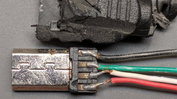
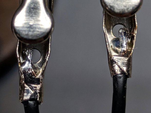
    My coax cable and clip lead collection includes everything from “I’ve had it forever” to “Recent cheap crap”, including much of Mad Phil’s collection. Some of the recent crap included Chinese clip leads with what can charitably be described as marginal connections:

    Alligator clips - bent wire
    Alligator clips – bent wire

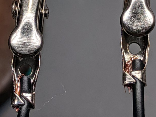
    The insulation may provide some compliance in the crimp, but the alligator clip itself consists of cheap steel which won’t hold a crimp, even if it was crimped firmly to start with.

    As a rule, the crimps aren’t particularly good:

    Black Dual Alligator - as manufactured
    Black Dual Alligator – as manufactured

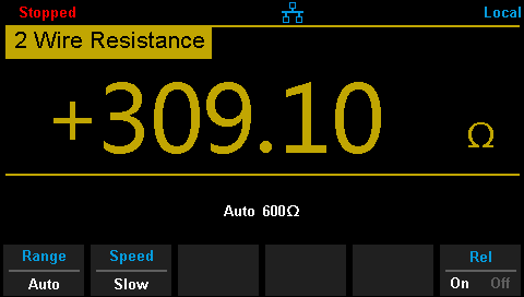
    The most obvious effect is high end-to-end resistance:

    Black Dual Alligator - before - A
    Black Dual Alligator – before – A

    Yes, yes, 122 Ω in an alligator clip lead is high.

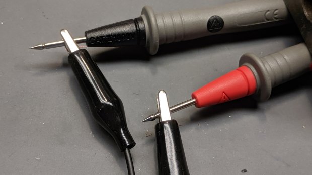
    The test setup isn’t particularly intricate:

    Black Dual Alligator - test setup
    Black Dual Alligator – test setup

    The lackadaisical crimps also have unstable resistances:

    Black Dual Alligator - before - B
    Black Dual Alligator – before – B

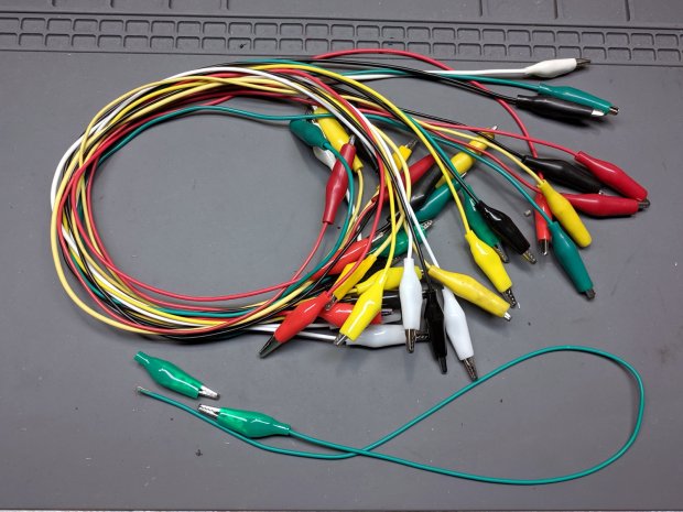
    So I figured I may as well repair the lot of ’em.

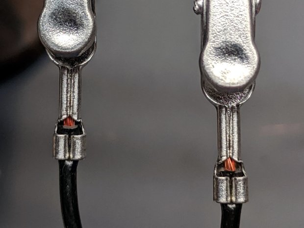
    I stripped the lead back to expose fresh copper, soldered it to the clip, then re-crimped the clip around the insulation for some token strain relief:

    Black Dual Alligator - soldered
    Black Dual Alligator – soldered

    I won’t win any soldering awards, but the resistance is way better than before:

    Black Dual Alligator - after
    Black Dual Alligator – after

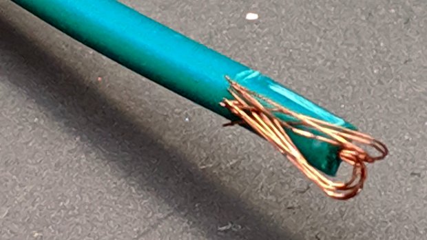
    If more than half an ohm seems a tad high for a foot of copper wire, you’re right. My slightly magnetized bench screwdriver shows it’s not copper wire:

    Copper-plated steel wire
    Copper-plated steel wire

    I’d say it’s copper-plated steel, wouldn’t you?

    Those of long memory will recall the non-standard ribbon cable I used as a 60 kHz loop antenna. In this case, the Chinese manufacturer figured nobody would notice or, likely, care. Given the crappy overall quality of the end product, it’s a fair assumption.

    I was mildly tempted to replace the wire with good silicone-insulated copper, but came to my senses; those “high voltage” silicone test leads will be Good Enough for higher-current connections.

    While I was at it, I pulled apart my entire collection just to see what was inside and fix the ailing ones. These clips date back to the dawn of time, with what started as excellent crimps:

    Crimped Alligator Clips - as manufactured
    Crimped Alligator Clips – as manufactured

    Alas, after I-don’t-know-how-many decades, they’re not longer gas-tight, so I soaked a dollop of solder into each one:

    Crimped Alligator Clips - soldered - Made In Japan
    Crimped Alligator Clips – soldered – Made In Japan

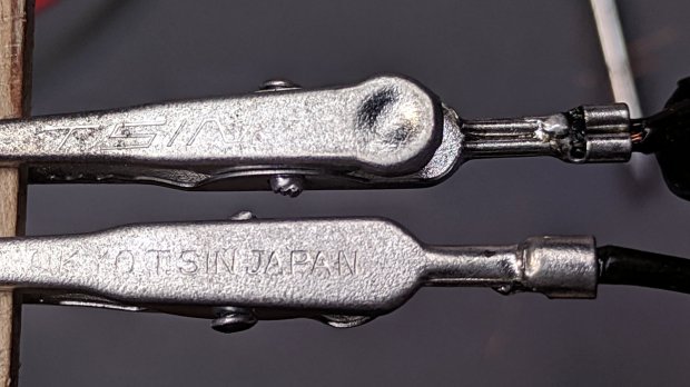
    Chekkitout: “Made In Japan”.

    Someone, perhaps me wearing a younger man’s clothes or, less likely, Mad Phil in a hurry, solved a similar problem with bigger blobs and no strain relief:

    Crimped Alligator Clips - cut and soldered
    Crimped Alligator Clips – cut and soldered

    So, now I have a slightly better collection of crappy alligator clip leads. The copper-plated steel wires will eventually fail, but it should become obvious when they do.

    Test your clip leads today!

  • CNC 3018-Pro: CAMTool Modification for MBI-style Home Switches

    The Protonteer board I used on the MPCNC required a few additional pins for power to Makerbot-style home switches, so it’s no surprise the CAMTool V3.3 board on the CNC 3018-Pro gantry mill requires a similar hack:

    3018 CNC CAMTool - Endstop power mod
    3018 CNC CAMTool – Endstop power mod

    The white jumper plugs into the single +5 V pin in the row and is soldered to a straight wire running along the entire row of header pins. I pushed the black plastic strip to the bottom, soldered the wire along the pins atop it, then clipped off the pins so they’re about the right height when flush against the PCB.

    Use a two-row socket to hold the new row in alignment with the existing header:

    3018 CNC CAMTool - Endstop power mod - alignment
    3018 CNC CAMTool – Endstop power mod – alignment

    Slobber on some epoxy and let it cure:

    3018 CNC CAMTool - Endstop power mod - epoxy curing
    3018 CNC CAMTool – Endstop power mod – epoxy curing

    And then It Just Works™:

    3018 CNC CAMTool - Endstop power mod - installed
    3018 CNC CAMTool – Endstop power mod – installed

    Well, after you install the switches and tell GRBL to use them …

    Reminder: If you intend to put limit switches on both ends of the axis travel, you must clip the NC lead from both MBI switches. One switch per axis will work the way you expect and that’s how I’m using them here.

  • Logitech “Quickcam for Notebooks Deluxe” USB Camera Disassembly

    My collection of old USB cameras emitted a Logitech Quickcam for Notebooks Deluxe, with a tag giving a cryptic M/N of V-UGB35. Given Logitech’s penchant for overlapping names, its USB identifiers may be more useful for positive ID:

    ID 046d:08d8 Logitech, Inc. QuickCam for Notebook Deluxe

    It works fine as a simple V4L camera and its 640×480 optical resolution may suffice for simple purposes, even if it’s not up to contemporary community standards.

    The key disassembly step turned out to be simply pulling the pivoting base off, then recovering an errant spring clip from the Laboratory Floor:

    Logitech V-UGB35 USB Camera - mount removed
    Logitech V-UGB35 USB Camera – mount removed

    The clips have a beveled side and fit into their recesses in only one orientation; there’s no need for brute force.

    Removing the two obvious case screws reveals the innards:

    Logitech V-UGB35 USB Camera - PCB rear
    Logitech V-UGB35 USB Camera – PCB rear

    Three more screws secure the PCB:

    Logitech V-UGB35 USB Camera - PCB front
    Logitech V-UGB35 USB Camera – PCB front

    The ribbed focus knob around the lens makes it more useful than a nominally fixed-focus camera.

    Reassembly is in reverse order.

    I miss having obvious case screws …

  • Warm-White LED Strip: FAIL

    The roll of warm-white LEDs I used for the first sewing machine lights has evidently aged out:

    Failed warm-white LED strip
    Failed warm-white LED strip

    They’ve been wrapped on their original roll, tucked in an antistatic bag, for the last five years, so it’s not as if they’ve been constantly abused.

    All the cool-white LEDs on an adjacent roll in the same bag still work perfectly, so you’re looking at inherent vice.

    I harvested the three longest functional sections and dumped the remainder in the electronics recycling box.

    COB LEDs provide much more light, if only because they run at higher power densities, and seem to be much better cost-performers:

    Juki TL-2010Q COB LED - installed - rear view
    Juki TL-2010Q COB LED – installed – rear view

    Admittedly, I haven’t looked at the RGB LED strips in a while, either.

  • Baofeng UV-5R Squelch Settings

    The Baofeng UV-5R radios on our bikes seem absurdly sensitive to intermodulation interference, particularly on rides across the Walkway Over the Hudson, which has a glorious view of the repeaters and paging transmitters atop Illinois Mountain:

    Walkway Over The Hudson - Illinois Mountain Antennas
    Walkway Over The Hudson – Illinois Mountain Antennas

    A better view of the assortment on the right:

    Illinois Mountain - North Antennas
    Illinois Mountain – North Antennas

    And on the left:

    Illinois Mountain - South Antennas
    Illinois Mountain – South Antennas

    Not shown: the Sheriff’s Office transmitter behind us on the left and the Vassar Brothers Hospital / MidHudson pagers on either side at eye level. There’s plenty of RFI boresighted on the Walkway.

    Anyhow, none of the Baofeng squelch settings had any effect, which turned out to be a known problem. The default range VHF covered a whopping 6 dB and the UHF wasn’t much better at 18 dB, both at very low RF power levels.

    We use the radios in simplex mode, generally within line of sight, so I changed the Service Settings to get really aggressive squelch:

    Baofeng UV-5R - Improved Squelch Settings
    Baofeng UV-5R – Improved Squelch Settings

    I have no way to calibrate the new signal levels, but I’d previously cranked the squelch up to 9 (it doesn’t go any higher) and, left unchanged, the new level makes all the previous interference Go Away™. Another ride over the Walkway with the squelch set to 4 also passed in blissful silence.

    If the BF-F9 levels mean anything on a UV-5R, that’s about -100 dBm, 20 dB over the previous -120 dBm at squelch = 9.

    The new squelch levels may be too tight for any other use, which doesn’t matter for these radios. As of now, our rides are quiet.

    [Update: Setting the squelch to 5 may be necessary for the Walkway, as we both heard a few squawks and bleeps while riding eastbound on a Monday afternoon. ]

  • Vacuum Tube LEDs: Failed Tape, Failed USB Cable

    While packing the vacuum tube LEDs for the HV Open Mad Science Fair, I noticed the knockoff Arduino Nano inside one had come unstuck from the base. It seems the double-stick foam tape I’d used had lost its sticky:

    Vacuum Tube LEDs - unstuck foam tape
    Vacuum Tube LEDs – unstuck foam tape

    Replacing it with my now-standard black 3M outdoor rated tape ought to solve the problem forever more.

    For whatever it’s worth, the SK6812 RGBW LEDs have had exactly zero failures in the last two years or so; I finally turned off the test fixture.

    Before reassembling the light, I plugged the USB cable into the bench supply and watched the Nano reset erratically. Careful poking showed the USB cable was intermittent, so I carved it up:

    Failed USB cable - autopsy
    Failed USB cable – autopsy

    As far as I can tell, the black wire (supply common) was cut mostly all the way through, with just a few strands remaining, before I peeled the insulation back.

    A closer look at the solder joints doesn’t inspire much confidence in their QC:

    Failed USB cable - solder joints
    Failed USB cable – solder joints

    If those pads tarnished along with their solder blobs, the overmolded plastic isn’t the right stuff for the job. If they started life like that … ick.

    I must up my cable spend, although I have no confidence doing so will improve the quality.

  • Exhibit Hand-Out Cards: QR Version

    I’ve finally had it beaten into my head: any public exhibition requires paper handouts, if only for younger folks who are too shy to ask questions. Paper may seem obsolete, but it serves as a physical reminder long after the sensory overload of a busy event fades away.

    Hence, I made up cards describing my exhibits at the HV Open Mad Science Fair, each sporting a QR code aimed at far more background information than anybody should care about:

    Mad Science Fair - handout cards
    Mad Science Fair – handout cards

    The QR codes come from one-liners:

    qrencode https://softsolder.com/?s=dso150 -s 5 -d 300 -o dso150.png

    So, go ahead, shoot ’em with your phone:

    • Blog search QR code: astable
    • Blog search QR code: bowl-of-fire
    • Blog search QR code: dso150
    • Blog search QR code: halogen
    • Blog search QR code: hp7475a
    • Blog search QR code: tubes

    Memo to Self: put the cards in the Big Box o’ Stuff the night before.