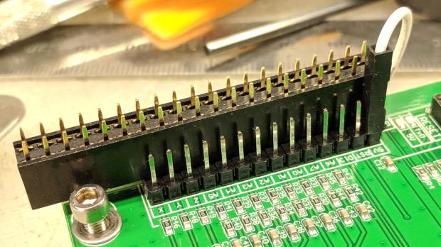
The CAMTool V3.3 board on the CNC 3018-Pro hardwires the three DRV8825 stepper driver chips in 1:32 microstep mode by pulling all three Mode pins high. Unlike most CNC boards, it does not include jumpers to let you select different microstep modes; the designers know you want as many microsteps as you can possibly get.
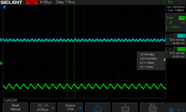
As it turns out, 1:32 microstep mode requires 1600 steps for each millimeter of travel and, because GRBL tops out around 30 k step/s, the maximum speed is about 18.75 mm/s = 1125 mm/min. Which isn’t at bad, but, because I intend to use the thing for engraving, rather than the light-duty machining it’s (allegedly) capable of performing, running at somewhat higher speeds will be desirable.
For sure, a 3018-Pro does not have a physical resolution of 625 nm.
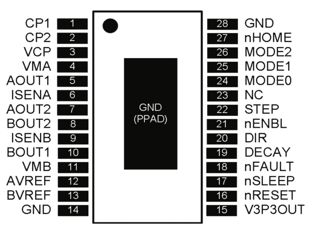
If you’re willing to settle for a mere 400 step/mm = 2.6 µm, then you can just ground the Mode 2 pin to get 1:8 microstep mode:

Rewiring the CAMTool board isn’t feasible, but hacking the DRV8825 carrier PCB doesn’t require much effort.
So, we begin.
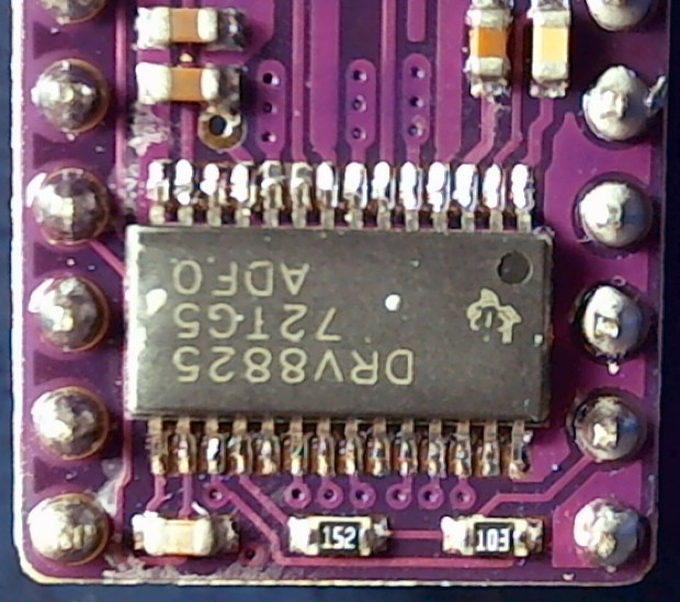
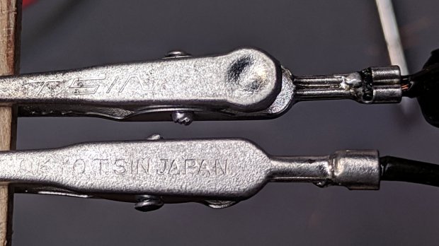
Clamp the PCB in a vise, grab the Mode 2 pin with a needle-nose pliers, apply enough heat to melt the solder completely through the board, and yank that pin right out:
I do wonder how the layout folks managed to reverse the “N” for the Enable pin. Perhaps it’s a Cyrillic И in a dead-simple font?
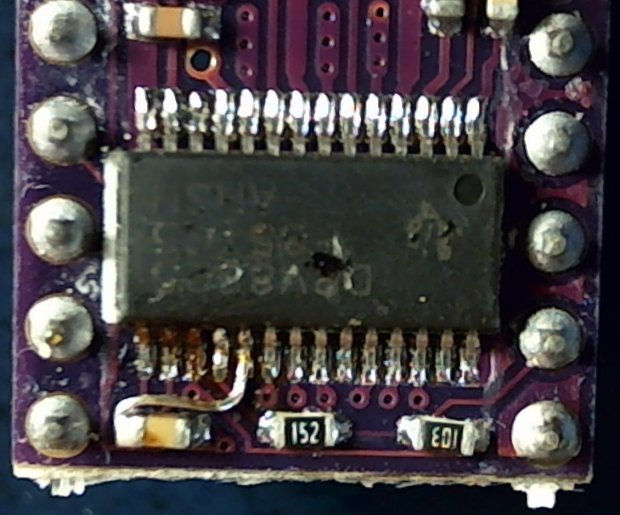
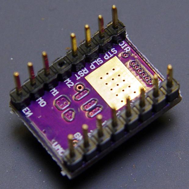
With that done, add a snippet of wire from M2 to the GND pin in the opposite corner to complete the job:
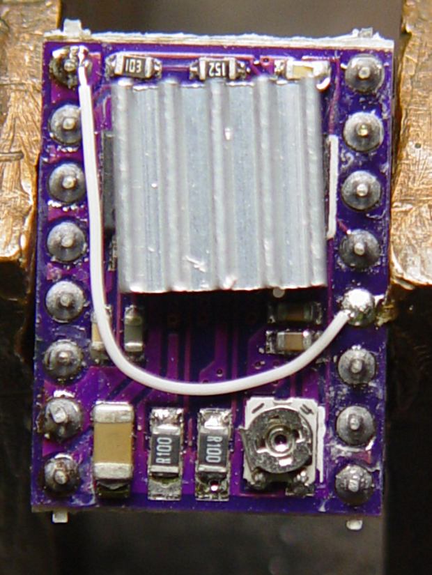
Despite that picture, remember to plug the DRV8825 boards into the CAMTool V3.3 board with the heatsink downward and the twiddlepot on the top, as shown in the little instruction book you got with the hardware:

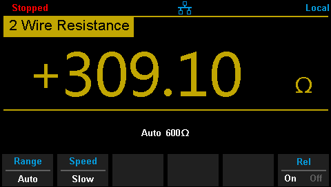
Recompute the step/mm value in 1:8 microstep mode:
400 step/mm = (200 full step/rev) × (8 microstep/full step) / (4 mm/rev)Then set the corresponding GRBL parameters:
$100=400
$101=400
$102=400
The 3018-Pro should work exactly like it did before, maybe a little noisier if your ears are up to the task.
Moah Speed comes later …