|
EESchema Schematic File Version 4 |
|
EELAYER 30 0 |
|
EELAYER END |
|
$Descr USLetter 11000 8500 |
|
encoding utf-8 |
|
Sheet 1 1 |
|
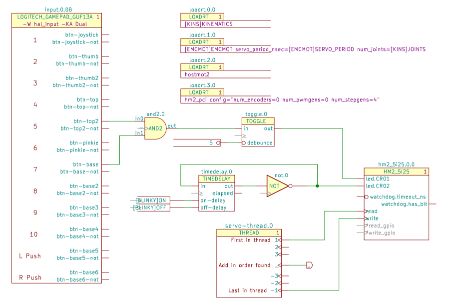
Title "Kicad-to-HAL Demo Schematic" |
|
Date "2021-03-23" |
|
Rev "" |
|
Comp "Ed Nisley – KE4ZNU" |
|
Comment1 "" |
|
Comment2 "" |
|
Comment3 "" |
|
Comment4 "" |
|
$EndDescr |
|
$Comp |
|
L LinuxCNC-HAL:THREAD servo-thread.0 |
|
U 1 1 6059ED1C |
|
P 5650 5200 |
|
F 0 "servo-thread.0" H 5650 5750 59 0000 C CNN |
|
F 1 "THREAD" H 5650 5650 50 0000 C CNN |
|
F 2 "" H 5750 5300 50 0001 C CNN |
|
F 3 "" H 5750 5300 50 0001 C CNN |
|
F 4 "1" H 6050 5650 50 0000 C CNN "StripAnno" |
|
1 5650 5200 |
|
1 0 0 -1 |
|
$EndComp |
|
$Comp |
|
L LinuxCNC-HAL:LOGITECH_GAMEPAD_GUF13A input.0.0 |
|
U 2 1 605A12D7 |
|
P 3000 3500 |
|
F 0 "input.0.0" H 3000 5350 50 0000 C CNN |
|
F 1 "LOGITECH_GAMEPAD_GUF13A" H 2950 5250 50 0000 C CNN |
|
F 2 "" H 8500 7100 50 0001 C CNN |
|
F 3 "" H 8500 7100 50 0001 C CNN |
|
F 4 "1" H 3550 5250 50 0000 C CNN "StripAnno" |
|
F 5 "-W hal_input -KA Dual" H 2950 5150 50 0000 C CNN "LoadUsr" |
|
2 3000 3500 |
|
1 0 0 -1 |
|
$EndComp |
|
$Comp |
|
L LinuxCNC-HAL:AND2 and2.0 |
|
U 1 1 605A4CD8 |
|
P 4350 3300 |
|
F 0 "and2.0" H 4350 3500 50 0000 C CNN |
|
F 1 "AND2" H 4350 3300 50 0000 C CNN |
|
F 2 "" H 4350 3300 50 0001 C CNN |
|
F 3 "" H 4350 3300 50 0001 C CNN |
|
F 4 "+" H 4350 3300 50 0001 C CNN "LoadRT" |
|
1 4350 3300 |
|
1 0 0 -1 |
|
$EndComp |
|
Wire Wire Line |
|
3700 3800 3850 3800 |
|
Wire Wire Line |
|
3850 3800 3850 3400 |
|
Wire Wire Line |
|
3850 3400 4050 3400 |
|
Wire Wire Line |
|
4050 3200 3700 3200 |
|
$Comp |
|
L LinuxCNC-HAL:TOGGLE toggle.0 |
|
U 1 1 605A7FF1 |
|
P 5750 3400 |
|
F 0 "toggle.0" H 5750 3700 50 0000 C CNN |
|
F 1 "TOGGLE" H 5750 3600 50 0000 C CNN |
|
F 2 "" H 6050 3350 50 0001 C CNN |
|
F 3 "" H 6050 3350 50 0001 C CNN |
|
F 4 "+" H 5750 3400 50 0001 C CNN "LoadRT" |
|
1 5750 3400 |
|
1 0 0 -1 |
|
$EndComp |
|
$Comp |
|
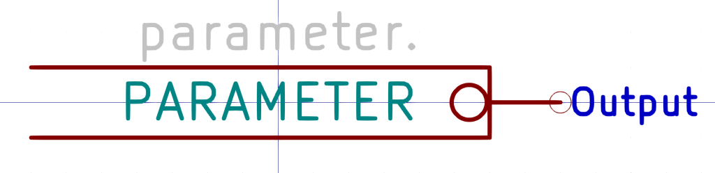
L LinuxCNC-HAL:PARAMETER parameter.0 |
|
U 1 1 605A8894 |
|
P 4950 3500 |
|
F 0 "parameter.0" H 4950 3600 50 0001 C CNN |
|
F 1 "5" H 5150 3500 50 0000 R CNN |
|
F 2 "" H 5250 3500 50 0001 C CNN |
|
F 3 "" H 5250 3500 50 0001 C CNN |
|
1 4950 3500 |
|
1 0 0 -1 |
|
$EndComp |
|
$Comp |
|
L LinuxCNC-HAL:HM2_5I25 hm2_5i25.0.0 |
|
U 1 1 605A8E84 |
|
P 7700 4300 |
|
F 0 "hm2_5i25.0.0" H 7700 4800 50 0000 C CNN |
|
F 1 "HM2_5I25" H 7700 4700 50 0000 C CNN |
|
F 2 "" H 8250 4100 50 0001 C CNN |
|
F 3 "" H 8250 4100 50 0001 C CNN |
|
F 4 "1" H 8100 4700 50 0000 C CNN "StripAnno" |
|
1 7700 4300 |
|
1 0 0 -1 |
|
$EndComp |
|
Wire Wire Line |
|
4650 3300 5450 3300 |
|
Wire Wire Line |
|
5350 3500 5500 3500 |
|
Wire Wire Line |
|
6100 3300 6950 3300 |
|
Wire Wire Line |
|
7150 4550 6900 4550 |
|
Wire Wire Line |
|
6900 4550 6900 5550 |
|
Wire Wire Line |
|
6900 5550 6200 5550 |
|
$Comp |
|
L LinuxCNC-HAL:LOADRT loadrt.3.? |
|
U 1 1 605AF190 |
|
P 5000 2950 |
|
AR Path="/6047689B/605AF190" Ref="loadrt.3.?" Part="1" |
|
AR Path="/605AF190" Ref="loadrt.3.0" Part="1" |
|
F 0 "loadrt.3.0" H 5000 3200 50 0000 C CNN |
|
F 1 "LOADRT" H 4950 3100 50 0000 C CNN |
|
F 2 "" H 5800 2450 50 0001 C CNN |
|
F 3 "https://linuxcnc.org/docs/2.8/html/hal/basic-hal.html#_loadrt" H 5800 2450 50 0001 C CNN |
|
F 4 "hm2_pci config=\"num_encoders=0 num_pwmgens=0 num_stepgens=4\"" H 4750 3000 50 0000 L CNN "LoadRT" |
|
F 5 "1" H 5250 3100 50 0000 C CNN "StripAnno" |
|
1 5000 2950 |
|
1 0 0 -1 |
|
$EndComp |
|
$Comp |
|
L LinuxCNC-HAL:LOADRT loadrt.2.? |
|
U 1 1 605AF198 |
|
P 5000 2600 |
|
AR Path="/6047689B/605AF198" Ref="loadrt.2.?" Part="1" |
|
AR Path="/605AF198" Ref="loadrt.2.0" Part="1" |
|
F 0 "loadrt.2.0" H 5000 2850 50 0000 C CNN |
|
F 1 "LOADRT" H 4950 2750 50 0000 C CNN |
|
F 2 "" H 5800 2100 50 0001 C CNN |
|
F 3 "https://linuxcnc.org/docs/2.8/html/hal/basic-hal.html#_loadrt" H 5800 2100 50 0001 C CNN |
|
F 4 "hostmot2" H 4750 2650 50 0000 L CNN "LoadRT" |
|
F 5 "1" H 5250 2750 50 0000 C CNN "StripAnno" |
|
1 5000 2600 |
|
1 0 0 -1 |
|
$EndComp |
|
Text GLabel 6450 5200 2 50 Output ~ 0 |
|
_ |
|
$Comp |
|
L LinuxCNC-HAL:LOADRT loadrt.0.? |
|
U 1 1 605B697F |
|
P 5000 1900 |
|
AR Path="/6047689B/605B697F" Ref="loadrt.0.?" Part="1" |
|
AR Path="/605B697F" Ref="loadrt.0.0" Part="1" |
|
F 0 "loadrt.0.0" H 5000 2150 50 0000 C CNN |
|
F 1 "LOADRT" H 4950 2050 50 0000 C CNN |
|
F 2 "" H 5800 1400 50 0001 C CNN |
|
F 3 "https://linuxcnc.org/docs/2.8/html/hal/basic-hal.html#_loadrt" H 5800 1400 50 0001 C CNN |
|
F 4 "[KINS]KINEMATICS" H 4750 1950 50 0000 L CNN "LoadRT" |
|
F 5 "1" H 5250 2050 50 0000 C CNN "StripAnno" |
|
1 5000 1900 |
|
1 0 0 -1 |
|
$EndComp |
|
$Comp |
|
L LinuxCNC-HAL:LOADRT loadrt.1.? |
|
U 1 1 605B6987 |
|
P 5000 2250 |
|
AR Path="/6047689B/605B6987" Ref="loadrt.1.?" Part="1" |
|
AR Path="/605B6987" Ref="loadrt.1.0" Part="1" |
|
F 0 "loadrt.1.0" H 5000 2500 50 0000 C CNN |
|
F 1 "LOADRT" H 4950 2400 50 0000 C CNN |
|
F 2 "" H 5800 1750 50 0001 C CNN |
|
F 3 "https://linuxcnc.org/docs/2.8/html/hal/basic-hal.html#_loadrt" H 5800 1750 50 0001 C CNN |
|
F 4 "[EMCMOT]EMCMOT servo_period_nsec=[EMCMOT]SERVO_PERIOD num_joints=[KINS]JOINTS" H 4750 2300 50 0000 L CNN "LoadRT" |
|
F 5 "1" H 5250 2400 50 0000 C CNN "StripAnno" |
|
1 5000 2250 |
|
1 0 0 -1 |
|
$EndComp |
|
Wire Wire Line |
|
6200 5200 6450 5200 |
|
Wire Wire Line |
|
6700 4450 7150 4450 |
|
Wire Wire Line |
|
6700 4450 6700 4850 |
|
Wire Wire Line |
|
6700 4850 6200 4850 |
|
$Comp |
|
L LinuxCNC-HAL:TIMEDELAY timedelay.0 |
|
U 1 1 605C692D |
|
P 5200 4250 |
|
F 0 "timedelay.0" H 5200 4600 50 0000 C CNN |
|
F 1 "TIMEDELAY" H 5200 4500 50 0000 C CNN |
|
F 2 "" H 5200 4400 50 0001 C CNN |
|
F 3 "" H 5200 4400 50 0001 C CNN |
|
F 4 "+" H 5200 4250 50 0001 C CNN "LoadRT" |
|
1 5200 4250 |
|
1 0 0 -1 |
|
$EndComp |
|
$Comp |
|
L LinuxCNC-HAL:CONSTANT constant.0 |
|
U 1 1 605C7C1F |
|
P 4350 4300 |
|
F 0 "constant.0" H 4350 4400 50 0001 C CNN |
|
F 1 "[BLINKY]ON" H 4500 4300 50 0000 R CNN |
|
F 2 "" H 4600 4050 50 0001 C CNN |
|
F 3 "" H 4600 4050 50 0001 C CNN |
|
F 4 "+" H 4350 4300 50 0001 C CNN "LoadRT" |
|
1 4350 4300 |
|
1 0 0 -1 |
|
$EndComp |
|
$Comp |
|
L LinuxCNC-HAL:CONSTANT constant.1 |
|
U 1 1 605C822C |
|
P 4350 4400 |
|
F 0 "constant.1" H 4350 4500 50 0001 C CNN |
|
F 1 "[BLINKY]OFF" H 4500 4400 50 0000 R CNN |
|
F 2 "" H 4600 4150 50 0001 C CNN |
|
F 3 "" H 4600 4150 50 0001 C CNN |
|
F 4 "+" H 4350 4400 50 0001 C CNN "LoadRT" |
|
1 4350 4400 |
|
1 0 0 -1 |
|
$EndComp |
|
Wire Wire Line |
|
4750 4300 4850 4300 |
|
Wire Wire Line |
|
4750 4400 4850 4400 |
|
Wire Wire Line |
|
7150 4000 6950 4000 |
|
Wire Wire Line |
|
6950 4000 6950 3300 |
|
$Comp |
|
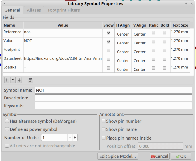
L LinuxCNC-HAL:NOT not.0 |
|
U 1 1 605D425F |
|
P 6000 4100 |
|
F 0 "not.0" H 6100 4250 50 0000 C CNN |
|
F 1 "NOT" H 6000 4100 50 0000 C CNN |
|
F 2 "" H 6350 3850 50 0001 C CNN |
|
F 3 "" H 6350 3850 50 0001 C CNN |
|
F 4 "+" H 6000 4100 50 0001 C CNN "LoadRT" |
|
1 6000 4100 |
|
1 0 0 -1 |
|
$EndComp |
|
Wire Wire Line |
|
5550 4100 5750 4100 |
|
Wire Wire Line |
|
6450 4100 6600 4100 |
|
Wire Wire Line |
|
6600 4100 6600 3800 |
|
Wire Wire Line |
|
6600 3800 4700 3800 |
|
Wire Wire Line |
|
4700 3800 4700 4100 |
|
Wire Wire Line |
|
4700 4100 4850 4100 |
|
Wire Wire Line |
|
6600 4100 7150 4100 |
|
Connection ~ 6600 4100 |
|
$EndSCHEMATC |