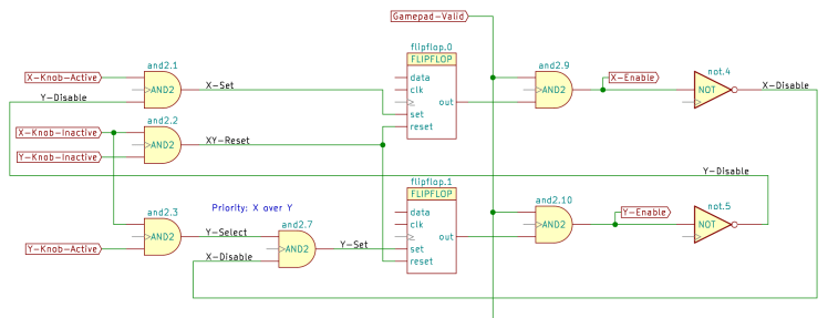
So it turns out a few hundred lines of Python can convert a Kicad schematic:
Into a LinuxCNC HAL machine configuration file:
loadrt and2		count=22
loadrt flipflop		count=5
loadrt not		count=8
<<< … etc … >>>

addf and2.0		servo-thread
<<< … etc … >>>

net X-Knob-Active <= or2.2.out => and2.1.in0 not.0.in
net X-Knob-Inactive <= not.0.out => and2.2.in0 and2.3.in0
<<< … etc … >>>
net Y-Knob-Active <= or2.3.out => and2.3.in1 not.1.in
net Y-Knob-Inactive <= not.1.out => and2.2.in1
<<< … etc … >>>
net _Axis_Priority_XY-Reset <= and2.2.out => flipflop.0.reset flipflop.1.reset
net _Axis_Priority_Y-Disable <= not.5.out => and2.1.in1
net _Axis_Priority_Y-Select <= and2.3.out => and2.7.in0
net _Axis_Priority_Y-Set <= and2.7.out => flipflop.1.set
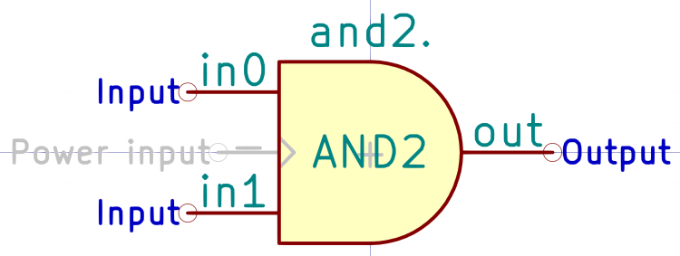
The Kicad schematic interconnects components from a library defining LinuxCNC HAL devices:
The process goes a little something like this:
- Draw schematic using components in
LinuxCNC-HAL.lib - Add missing components to
LinuxCNC-HAL.lib - Iterate
- Annotate schematic
(starting from 0) - Generate netlist in XML format
- Run
Kicad-to-HAL.pywith Python 3.9.2 (sorry) - Fix whatever LinuxCNC complains about
- Iterate
- Fix logic flaws by adjusting schematic
- Iterate
The Kicad components include magick HAL features, the Python program rides roughshod over Kicad conventions, and this thing stands deep in “It works for me!” territory, but I must coerce my notes into something resembling coherence before I forget the grisly details.
More to follow, but you can peruse the Python3 source code and Kicad library as a GitHub Gist:
This file contains hidden or bidirectional Unicode text that may be interpreted or compiled differently than what appears below. To review, open the file in an editor that reveals hidden Unicode characters.
Learn more about bidirectional Unicode characters
| # Parse Kicad schematic netlist into a LinuxCNC HAL configuration file | |
| # | |
| # Ed Nisley – KE4ZNU | |
| # 2021-03 | |
| import argparse | |
| from pathlib import Path | |
| from lxml import etree | |
| # ———- | |
| # remove Kicad annotation from reference as needed | |
| # kref = Kicad annotated reference | |
| # component has field entries for anything other than and value | |
| def cleanHALref(kref): | |
| comp = etree.XPath('comp[@ref="' + kref + '"]')(components)[0] | |
| fields = etree.XPath('fields/field[@name="StripAnno"]')(comp) | |
| if len(fields) and (fields[0].text).startswith("1"): | |
| retval = kref.rpartition(".")[0] | |
| else: | |
| retval = kref | |
| # print('strip: {} -> {}'.format(kref,retval)) | |
| return retval | |
| # ———- | |
| # do the whole thing | |
| parser = argparse.ArgumentParser( | |
| description="Process Kicad schematic netlist into LinuxCNC HAL configuration file" | |
| ) | |
| parser.add_argument("netlist", help="input: Kicad XML netlist file describing HAL configuration") | |
| parser.add_argument("hal", help="output: LinuxCNC HAL configuration file") | |
| args = parser.parse_args() | |
| xmlfn = Path(args.netlist) | |
| if not xmlfn.exists(): | |
| print("** No such file: {!s}".format(xmlfn)) | |
| exit() | |
| print("Opening XML file: {!s}".format(xmlfn)) | |
| Netlist = etree.parse(xmlfn.name) | |
| halfn = Path(args.hal) | |
| if halfn is None: | |
| halfn = xmlfn.with_name(xmlfn.stem + ".hal") | |
| print("Writing HAL file: {!s}".format(halfn)) | |
| halfile = open(halfn, "w") | |
| design = etree.XPath("//design")(Netlist)[0] | |
| print("XML date: {}".format(etree.XPath("date")(design)[0].text)) | |
| libraries = etree.XPath("//libraries")(Netlist)[0] | |
| print("Libraries:") | |
| for l in libraries: | |
| print(" {}".format(etree.XPath("uri")(l)[0].text)) | |
| components = etree.XPath("//components")(Netlist)[0] | |
| print("Components: {:.0f}".format(etree.XPath("count(comp)")(components))) | |
| libparts = etree.XPath("//libparts")(Netlist)[0] | |
| print("Library parts: {:.0f}".format(etree.XPath("count(libpart)")(libparts))) | |
| nets = etree.XPath("//nets")(Netlist)[0] | |
| print("Nets: {:.0f}".format(etree.XPath("count(net)")(nets))) | |
| halfile.write("# LinuxCNC HAL file\n\n# Kicad netlist: {}\n".format(xmlfn)) | |
| halfile.write("# {}\n\n".format(etree.XPath("date")(design)[0].text)) | |
| # —– | |
| # load realtime modules | |
| # LOADRT components | |
| comps = etree.XPath('comp[value="LOADRT"]')(components) | |
| comps.sort(key=lambda r: r.attrib["ref"]) | |
| # print('LRT sort: {}'.format(comps)) | |
| llist = [] | |
| for comp in comps: | |
| ref = comp.attrib["ref"] | |
| fld = etree.XPath('fields/field[@name="LoadRT"]')(comp)[0] | |
| # print(' cfg: {} -> {}'.format(ref,fld.text)) | |
| llist += ["loadrt {}\t\t# {}".format(fld.text, ref)] | |
| if len(llist): | |
| llist += [" "] | |
| # collect all other components with a LoadRT field | |
| # a leading + indicates a component using Kicad reference counting | |
| # concatenate rest of field in order of ref sequence | |
| rtfs = etree.XPath('comp[value!="LOADRT"]/fields/field[@name="LoadRT"]')(components) | |
| # print('Flds: {}'.format(rtfs)) | |
| rtfs.sort(key=lambda f: f.xpath("ancestor::comp")[0].attrib["ref"]) | |
| modules = {} | |
| for f in rtfs: | |
| comp = etree.XPath("ancestor::comp")(f)[0] | |
| ref = comp.attrib["ref"] | |
| mod = (etree.XPath("libsource")(comp)[0]).attrib["part"] | |
| # print(' ref: {} mod: {}'.format(ref,mod)) | |
| if f.text.startswith("+"): | |
| if mod in modules: | |
| modules[mod][0] += 1 | |
| modules[mod][1] += f.text.lstrip("+ ") | |
| else: | |
| modules.update({mod: [1, f.text.lstrip("+ ")]}) | |
| # print(" added {} {}".format(mod,modules[mod])) | |
| else: | |
| llist += ["loadrt {}\t{}\t\t# {}".format(mod, f.text, ref)] | |
| if len(modules): | |
| # print('modules: {}'.format(modules)) | |
| for mod, v in sorted(modules.items(), key=lambda kv: kv[0]): | |
| llist += ["loadrt {}\t\tcount={} {}".format(mod.lower(), v[0], v[1])] | |
| if len(llist): | |
| halfile.write("\n#——\n# LoadRT modules\n\n") | |
| halfile.write("\n".join(llist) + "\n") | |
| # —– | |
| # collect LoadUsr fields from components | |
| llist = [] | |
| ufs = etree.XPath('comp/fields/field[@name="LoadUsr"]')(components) | |
| # print('Flds: {}'.format(ufs)) | |
| for f in ufs: | |
| comp = etree.XPath("ancestor::comp")(f)[0] | |
| ref = comp.attrib["ref"] | |
| if len(f.text): | |
| llist += ["loadusr {}\t\t# {}".format(f.text, ref)] | |
| if len(llist): | |
| halfile.write("\n#——\n# LoadUsr modules\n\n") | |
| halfile.write("\n".join(llist) + "\n") | |
| # —– | |
| # collect power-input pins into addf statements | |
| halfile.write("\n#——\n# Function hookups\n\n") | |
| addflist = [] | |
| # find library THREAD part to get pins for addf sequencing | |
| tpart = etree.XPath('libpart[@part="THREAD"]')(libparts)[0] | |
| tpins = etree.XPath("pins/pin")(tpart) | |
| # print('tpart: {}'.format(tpart)) | |
| # print('tpins: {}'.format(tpins)) | |
| # step through all THREAD components | |
| tcomps = etree.XPath('comp[value="THREAD"]')(components) | |
| # print('tcomps: {}'.format(tcomps)) | |
| for tcomp in tcomps: | |
| tcref = tcomp.attrib["ref"] | |
| # print('tcomp: {} tref: {}'.format(tcomp,tcref)) | |
| for tpin in tpins: | |
| pnum = tpin.attrib["num"] | |
| pname = tpin.attrib["name"] | |
| # use pin number to find other nodes in net | |
| pnode = etree.XPath('net/node[@ref="' + tcref + '" and @pin="' + pnum + '"]')(nets)[0] | |
| nodes = etree.XPath("preceding-sibling::node")(pnode) | |
| nodes += etree.XPath("following-sibling::node")(pnode) | |
| # print('nodes: {}'.format(nodes)) | |
| if len(nodes) == 0: | |
| continue | |
| nlist = ["# Position: " + pname + "\n"] | |
| # print(' thread position: {}'.format(pname)) | |
| for node in nodes: | |
| ref = node.attrib["ref"] | |
| cleanref = cleanHALref(ref) | |
| pin = node.attrib["pin"] | |
| # print(' node: {} ref: {} = {} pin: {}'.format(node,ref,cleanref,pin)) | |
| # look up destination pin name to weed out "_" defaults | |
| # and find "/" prefix indicating no ref prefix | |
| dval = etree.XPath('comp[@ref="' + ref + '"]/value')(components)[0] | |
| # print(' dval: {} {}'.format(dval,dval.text)) | |
| dsrc = etree.XPath('comp[@ref="' + ref + '"]/libsource')(components)[0] | |
| dpart = dsrc.attrib["part"] | |
| # print(' dsrc: {} {}'.format(dsrc,dpart)) | |
| ldparts = etree.XPath('libpart[@part="' + dpart + '"]')(libparts) | |
| # print(' ldparts: {}'.format(ldparts)) | |
| if len(ldparts): | |
| ldpart = ldparts[0] | |
| ldpin = etree.XPath('pins/pin[@num="' + pin + '"]')(ldpart)[0] | |
| ldpname = ldpin.attrib["name"] | |
| # print(' ldpin: {} name: {} part: {}'.format(ldpin,ldpname,dpart)) | |
| if ldpname == "_": | |
| nlist += ["addf {}\t\t{}".format(cleanref, cleanHALref(tcref))] | |
| else: | |
| if ldpname.startswith("/"): | |
| nlist += [ | |
| "addf {}\t\t{}".format(ldpname.removeprefix("/"), cleanHALref(tcref)) | |
| ] | |
| else: | |
| nlist += ["addf {}.{}\t\t{}".format(cleanref, ldpname, cleanHALref(tcref))] | |
| if pname == "_": | |
| nlist.sort() | |
| addflist += nlist + [" "] | |
| if len(addflist): | |
| halfile.write("\n".join(addflist) + "\n") | |
| # —– | |
| # set parameter values | |
| # trace through nets to find other nodes to set | |
| params = 0 | |
| parlist = [] | |
| for comp in components: | |
| ref = comp.attrib["ref"] | |
| # ignore non-parameter components | |
| if not ref.startswith("parameter."): | |
| continue | |
| params += 1 | |
| value = etree.XPath("value")(comp)[0].text | |
| # print('param: {} = {}'.format(ref,value)) | |
| pnode = etree.XPath('net/node[@ref="' + ref + '"]')(nets)[0] | |
| nodes = etree.XPath("preceding-sibling::node")(pnode) + etree.XPath("following-sibling::node")( | |
| pnode | |
| ) | |
| for node in nodes: | |
| nref = node.attrib["ref"] | |
| npin = node.attrib["pin"] | |
| ncomp = etree.XPath('comp[@ref="' + nref + '"]')(components)[0] | |
| nls = etree.XPath("libsource")(ncomp)[0] | |
| nname = nls.attrib["part"] | |
| lpart = etree.XPath('libpart[@part="' + nname + '"]')(libparts)[0] | |
| lpin = etree.XPath('pins/pin[@num="' + npin + '"]')(lpart)[0] | |
| # print('ref: {} nref: {} npin: {} lpin: {}'.format(ref,cleanHALref(nref),npin,lpin)) | |
| parlist += [ | |
| "setp {}.{} {}\t\t# {}".format(cleanHALref(nref), lpin.attrib["name"], value, ref) | |
| ] | |
| if len(parlist): | |
| halfile.write("\n#——\n# Parameters\n\n") | |
| parlist.sort() | |
| halfile.write("\n".join(parlist) + "\n") | |
| print("Parameters: {}".format(params)) | |
| # —– | |
| # set constant parameters | |
| # the .value pin is hardcoded here to keep the schematic part tidy | |
| consts = 0 | |
| conlist = [] | |
| for comp in components: | |
| ref = comp.attrib["ref"] | |
| # ignore non-constant components | |
| if not ref.startswith("constant."): | |
| continue | |
| consts += 1 | |
| value = etree.XPath("value")(comp)[0].text | |
| # print('const: {} = {}'.format(ref,value)) | |
| pval = ref + ".value" | |
| conlist += ["setp {} {}".format(pval, value)] | |
| if len(conlist): | |
| halfile.write("\n#——\n# Constants\n\n") | |
| conlist.sort() | |
| halfile.write("\n".join(conlist) + "\n") | |
| print("Constants: {}".format(consts)) | |
| # —– | |
| # generate HAL net connections | |
| halfile.write("\n#——\n# Nets\n\n") | |
| hallist = [] | |
| single = 0 | |
| multi = 0 | |
| netID = 1 | |
| for net in nets: | |
| name = net.attrib["name"] | |
| # skip special net for unconnected addf functions | |
| if name == "_": | |
| multi += 1 | |
| continue | |
| # print('net {}'.format(net.attrib)) | |
| nodes = etree.XPath("node")(net) | |
| # skip single-pin nets | |
| # suppress error for pin names starting with * | |
| if len(nodes) < 2: | |
| if not (name.startswith("Net-") or name.startswith("*")): | |
| hallist += [ | |
| "#* Named net with single pin: {} {}\n".format(nodes[0].attrib["ref"], name) | |
| ] | |
| single += 1 | |
| continue | |
| nameclean = name.translate(name.maketrans("/ ", "__", "()")) | |
| # print('name: {} -> {}'.format(name,nameclean)) | |
| multi += 1 | |
| halstr = "net " | |
| halsinks = [] | |
| outputs = 0 | |
| for node in nodes: | |
| ref = node.attrib["ref"] | |
| pnum = node.attrib["pin"] | |
| # print('node: {}'.format(node.attrib)) | |
| comp = etree.XPath('comp[@ref="' + ref + '"]')(components)[0] | |
| ls = etree.XPath("libsource")(comp)[0] | |
| # print('libsource: {}'.format(ls.attrib)) | |
| lpart = etree.XPath('libpart[@part="' + ls.attrib["part"] + '"]')(libparts)[0] | |
| # print('libpart: {}'.format(lpart.attrib)) | |
| lpin = etree.XPath('pins/pin[@num="' + pnum + '"]')(lpart)[0] | |
| pname = lpin.attrib["name"] | |
| cleanname = pname.lstrip("*") | |
| ptype = lpin.attrib["type"] | |
| # print('pin: {} {}'.format(ptype,pname)) | |
| if ptype == "output": | |
| if name.startswith("Net-"): | |
| halstr += "N_{:0>3d} <= {}.{} => ".format(netID, cleanHALref(ref), cleanname) | |
| netID += 1 | |
| else: | |
| halstr += "{} <= {}.{} => ".format(nameclean, cleanHALref(ref), cleanname) | |
| outputs += 1 | |
| else: | |
| halsinks += [cleanHALref(ref) + "." + cleanname] | |
| halstr += " ".join(sorted(halsinks)) | |
| if "parameter" in halstr or "-thread" in halstr: # discard parameters and threads | |
| # print('discard: {}'.format(halstr)) | |
| multi -= 1 | |
| continue | |
| elif outputs == 0: | |
| halstr = "#* No output pins: {}\n".format(halstr) | |
| elif outputs > 1: | |
| halstr = "#* Multiple output pins: {}\n".format(halstr) | |
| # print('result {}'.format(halstr)) | |
| hallist += [halstr] | |
| if len(hallist): | |
| hallist.sort() | |
| halfile.write("\n".join(hallist) + "\n") | |
| halfile.write("\n#——\n# Done!\n") | |
| halfile.close() | |
| # print(' = 1 : {:d}'.format(single)) | |
| # print(' > 1 : {:d}'.format(multi)) |
This file contains hidden or bidirectional Unicode text that may be interpreted or compiled differently than what appears below. To review, open the file in an editor that reveals hidden Unicode characters.
Learn more about bidirectional Unicode characters
| EESchema-LIBRARY Version 2.4 | |
| #encoding utf-8 | |
| # | |
| # AND2 | |
| # | |
| DEF AND2 and2. 0 0 N Y 1 F N | |
| F0 "and2." 0 200 50 H V C CNN | |
| F1 "AND2" 0 0 50 H V C CNN | |
| F2 "" 0 0 50 H I C CNN | |
| F3 "" 0 0 50 H I C CNN | |
| F4 "+" 0 0 50 H I C CNN "LoadRT" | |
| DRAW | |
| A 0 0 150 0 900 0 1 0 f 150 0 0 150 | |
| A 0 0 150 0 -900 0 1 0 f 150 0 0 -150 | |
| P 4 0 1 0 0 150 -150 150 -150 -150 0 -150 f | |
| X in0 1 -300 100 150 R 50 50 1 1 I | |
| X in1 2 -300 -100 150 R 50 50 1 1 I | |
| X out 3 300 0 150 L 50 50 1 1 O | |
| X _ 4 -250 0 100 R 50 50 1 1 W NC | |
| ENDDRAW | |
| ENDDEF | |
| # | |
| # COMP | |
| # | |
| DEF COMP comp. 0 20 N Y 1 F N | |
| F0 "comp." -50 300 50 H V C CNN | |
| F1 "COMP" -50 200 50 H V C CNN | |
| F2 "" 300 -50 50 H I C CNN | |
| F3 "" 300 -50 50 H I C CNN | |
| F4 "+" 0 0 50 H I C CNN "LoadRT" | |
| DRAW | |
| T 0 -100 -50 50 0 0 0 + Normal 0 C C | |
| T 0 -100 50 50 0 0 0 – Normal 0 C C | |
| S 200 150 -300 250 0 1 0 f | |
| S -300 150 200 -350 1 1 0 N | |
| X in0 1 -400 50 100 R 50 50 1 1 I | |
| X out 2 300 50 100 L 50 50 1 1 O | |
| X in1 3 -400 -50 100 R 50 50 1 1 I | |
| X hyst 4 -400 -250 154 R 50 50 1 1 I I | |
| X _ 5 -400 -150 100 R 50 50 1 1 W NC | |
| X equal 6 300 -50 100 L 50 50 1 1 O | |
| ENDDRAW | |
| ENDDEF | |
| # | |
| # CONSTANT | |
| # | |
| DEF CONSTANT constant. 0 0 N N 1 F N | |
| F0 "constant." 0 100 50 H I C CNN | |
| F1 "CONSTANT" 150 0 50 H V R CNN | |
| F2 "" 250 -250 50 H I C CNN | |
| F3 "" 250 -250 50 H I C CNN | |
| F4 "+" 0 0 50 H I C CNN "LoadRT" | |
| DRAW | |
| P 4 0 1 0 -250 50 200 50 200 -50 -250 -50 N | |
| X out 1 400 0 200 L 50 50 1 1 O | |
| X _ 2 -350 0 100 R 50 50 1 1 W NC | |
| ENDDRAW | |
| ENDDEF | |
| # | |
| # CONV_FLOAT_S32 | |
| # | |
| DEF CONV_FLOAT_S32 conv-float-s32. 0 20 N Y 1 F N | |
| F0 "conv-float-s32." 0 300 50 H V C CNN | |
| F1 "CONV_FLOAT_S32" 0 200 50 H V C CNN | |
| F2 "" 0 0 50 H I C CNN | |
| F3 "" 0 0 50 H I C CNN | |
| F4 "+" 0 100 50 H I C CNN "LoadRT" | |
| DRAW | |
| S 400 150 -400 250 0 1 0 f | |
| S -400 150 400 -150 1 1 0 N | |
| X in 1 -500 100 100 R 50 50 1 1 I | |
| X clamp 2 -500 -100 157 R 50 50 1 1 I I | |
| X out-of-range 3 500 0 100 L 50 50 1 1 O | |
| X out 4 500 100 100 L 50 50 1 1 O | |
| X _ 5 -500 0 100 R 50 50 1 1 W NC | |
| ENDDRAW | |
| ENDDEF | |
| # | |
| # CONV_FLOAT_U32 | |
| # | |
| DEF CONV_FLOAT_U32 conv-float-u32. 0 40 N Y 1 F N | |
| F0 "conv-float-u32." 0 300 50 H V C CNN | |
| F1 "CONV_FLOAT_U32" 0 200 50 H V C CNN | |
| F2 "" 0 50 50 H I C CNN | |
| F3 "" 0 50 50 H I C CNN | |
| F4 "+" 0 100 50 H I C CNN "LoadRT" | |
| DRAW | |
| S -400 150 400 -150 1 1 0 N | |
| S 400 150 -400 250 1 1 0 f | |
| X in 1 -500 100 100 R 50 50 1 1 I | |
| X clamp 2 -500 -100 157 R 50 50 1 1 I I | |
| X out-of-range 3 500 0 100 L 50 50 1 1 O | |
| X out 4 500 100 100 L 50 50 1 1 O | |
| X _ 5 -500 0 100 R 50 50 1 1 W NC | |
| ENDDRAW | |
| ENDDEF | |
| # | |
| # DBOUNCE | |
| # | |
| DEF DBOUNCE dbounce. 0 20 N Y 1 F N | |
| F0 "dbounce." 0 300 50 H V C CNN | |
| F1 "DBOUNCE" 0 200 50 H V C CNN | |
| F2 "" 600 -350 50 H I C CNN | |
| F3 "" 600 -350 50 H I C CNN | |
| F4 "+" 0 0 50 H I C CNN "LoadRT" | |
| DRAW | |
| S 200 150 -200 250 0 1 0 f | |
| S -200 150 200 -150 1 1 0 N | |
| X in 1 -300 100 100 R 50 50 1 1 I | |
| X out 2 300 100 100 L 50 50 1 1 O | |
| X delay 3 -300 -100 100 R 50 50 1 1 I | |
| X _ 4 -300 0 100 R 50 50 1 1 W NC | |
| ENDDRAW | |
| ENDDEF | |
| # | |
| # FLIPFLOP | |
| # | |
| DEF FLIPFLOP flipflop. 0 20 N Y 1 F N | |
| F0 "flipflop." 0 450 50 H V C CNN | |
| F1 "FLIPFLOP" 0 350 50 H V C CNN | |
| F2 "" 400 -150 50 H I C CNN | |
| F3 "" 400 -150 50 H I C CNN | |
| F4 "+" 0 0 50 H I C CNN "LoadRT" | |
| DRAW | |
| S 200 300 -200 400 0 1 0 f | |
| S -200 300 200 -300 1 1 0 N | |
| X data 2 -300 200 100 R 50 50 1 0 I | |
| X out 5 300 0 100 L 50 50 1 0 O | |
| X reset 1 -300 -200 100 R 50 50 1 1 I | |
| X clk 3 -300 100 100 R 50 50 1 1 I | |
| X set 4 -300 -100 100 R 50 50 1 1 I | |
| X _ 6 -300 0 100 R 50 50 1 1 W NC | |
| ENDDRAW | |
| ENDDEF | |
| # | |
| # HALUI | |
| # | |
| DEF HALUI halui. 0 40 N Y 1 F N | |
| F0 "halui." 0 500 59 H V C CNN | |
| F1 "HALUI" 0 400 50 H V C CNN | |
| F2 "" -150 300 50 H I C CNN | |
| F3 "" -150 300 50 H I C CNN | |
| F4 "1" 350 400 50 H V C CNN "StripAnno" | |
| DRAW | |
| S -400 -300 400 350 0 1 0 N | |
| S -400 450 400 350 0 1 0 f | |
| X abort 1 -500 250 100 R 0 50 1 0 I | |
| X home-all 2 -500 100 100 R 50 50 1 1 I | |
| X mdi-command-00 ~ -500 -100 100 R 50 50 1 1 I | |
| X mdi-command-01 ~ -500 -200 100 R 50 50 1 1 I | |
| ENDDRAW | |
| ENDDEF | |
| # | |
| # HALUI_AXIS | |
| # | |
| DEF HALUI_AXIS halui.axis. 0 40 N Y 1 F N | |
| F0 "halui.axis." 0 400 50 H V C CNN | |
| F1 "HALUI_AXIS" 0 300 50 H V C CNN | |
| F2 "" 450 400 50 H I C CNN | |
| F3 "" 450 400 50 H I C CNN | |
| F4 "1" 500 300 50 H V C CNN "StripAnno" | |
| DRAW | |
| S -550 -50 550 250 0 1 0 N | |
| S 550 350 -550 250 0 1 0 f | |
| X jog-deadband 1 -650 50 100 R 50 50 1 1 I | |
| X jog-speed 2 -650 150 100 R 50 50 1 1 I | |
| X selected 3 650 150 100 L 50 50 1 1 O | |
| ENDDRAW | |
| ENDDEF | |
| # | |
| # HALUI_AXIS_L | |
| # | |
| DEF HALUI_AXIS_L halui.axis.x. 0 40 N Y 1 F N | |
| F0 "halui.axis.x." 0 400 50 H V C CNN | |
| F1 "HALUI_AXIS_L" 0 300 50 H V C CNN | |
| F2 "" -100 350 50 H I C CNN | |
| F3 "" -100 350 50 H I C CNN | |
| F4 "1" 600 300 50 H V C CNN "StripAnno" | |
| DRAW | |
| S -650 350 650 250 0 1 0 f | |
| S 650 250 -650 -600 0 1 0 N | |
| X analog 1 -750 50 100 R 50 50 1 1 I | |
| X pos-relative 10 750 -150 100 L 50 50 1 1 O | |
| X select 11 -750 200 100 R 50 50 1 1 I | |
| X increment 2 -750 -100 100 R 50 50 1 1 I | |
| X increment-minus 3 -750 -200 100 R 50 50 1 1 I | |
| X increment-plus 4 -750 -300 100 R 50 50 1 1 I | |
| X is-selected 5 750 200 100 L 50 50 1 1 O | |
| X minus 6 -750 -450 100 R 50 50 1 1 I | |
| X plus 7 -750 -550 100 R 50 50 1 1 I | |
| X pos-commanded 8 750 50 100 L 50 50 1 1 O | |
| X pos-feedback 9 750 -50 100 L 50 50 1 1 O | |
| ENDDRAW | |
| ENDDEF | |
| # | |
| # HALUI_AXIS_SELECTED | |
| # | |
| DEF HALUI_AXIS_SELECTED halui.axis.selected. 0 40 N Y 1 F N | |
| F0 "halui.axis.selected." 50 400 50 H V C CNN | |
| F1 "HALUI_AXIS_SELECTED" 50 300 50 H V C CNN | |
| F2 "" 1200 850 50 H I C CNN | |
| F3 "" 1200 850 50 H I C CNN | |
| F4 "1" 550 300 50 H V C CNN "StripAnno" | |
| DRAW | |
| S -500 -500 600 250 1 1 0 N | |
| S 600 350 -500 250 1 1 0 f | |
| X increment 1 -600 150 100 R 50 50 1 1 I | |
| X increment-minus 2 -600 0 100 R 50 50 1 1 I | |
| X increment-plus 3 -600 -100 100 R 50 50 1 1 I | |
| X minus 4 -600 -300 100 R 50 50 1 1 I | |
| X plus 5 -600 -400 100 R 50 50 1 1 I | |
| ENDDRAW | |
| ENDDEF | |
| # | |
| # HALUI_ESTOP | |
| # | |
| DEF HALUI_ESTOP halui.estop. 0 40 N Y 1 F N | |
| F0 "halui.estop." 0 300 50 H V C CNN | |
| F1 "HALUI_ESTOP" 0 200 50 H V C CNN | |
| F2 "" 0 0 50 H I C CNN | |
| F3 "" 0 0 50 H I C CNN | |
| F4 "1" 300 200 50 H V C CNN "StripAnno" | |
| DRAW | |
| S -350 -150 350 150 0 1 0 N | |
| S 350 150 -350 250 0 1 0 f | |
| X activate 1 -450 100 100 R 0 50 1 1 I | |
| X is-activated 2 450 0 100 L 0 50 1 1 O | |
| X reset 3 -450 -100 100 R 0 50 1 1 I | |
| ENDDRAW | |
| ENDDEF | |
| # | |
| # HALUI_FEED_OVERRIDE | |
| # | |
| DEF HALUI_FEED_OVERRIDE halui.feed-override. 0 40 N Y 1 F N | |
| F0 "halui.feed-override." 0 450 50 H V C CNN | |
| F1 "HALUI_FEED_OVERRIDE" 0 350 50 H V C CNN | |
| F2 "" 200 50 50 H I C CNN | |
| F3 "" 200 50 50 H I C CNN | |
| F4 "1" 500 350 50 H V C CNN "StripAnno" | |
| DRAW | |
| S -450 -400 450 300 0 1 0 N | |
| S 450 300 -450 400 0 1 0 f | |
| X count-enable 1 -550 250 100 R 0 50 1 1 I | |
| X counts 2 -550 150 100 R 0 50 1 1 I | |
| X decrease 3 -550 -100 100 R 0 50 1 1 I | |
| X direct-value 4 -550 -250 100 R 0 50 1 1 I | |
| X increase 5 -550 0 100 R 0 50 1 1 I | |
| X scale 6 -550 -350 100 R 0 50 1 1 I | |
| X value 7 550 250 100 L 0 50 1 1 O | |
| ENDDRAW | |
| ENDDEF | |
| # | |
| # HALUI_FLOOD | |
| # | |
| DEF HALUI_FLOOD halui.flood. 0 40 N Y 1 F N | |
| F0 "halui.flood." 0 250 50 H V C CNN | |
| F1 "HALUI_FLOOD" 0 150 50 H V C CNN | |
| F2 "" 0 0 50 H I C CNN | |
| F3 "" 0 0 50 H I C CNN | |
| F4 "1" 350 150 50 H V C CNN "StripAnno" | |
| DRAW | |
| S -300 100 300 -100 1 1 0 N | |
| S -300 200 300 100 1 1 0 f | |
| X is-on 1 400 0 100 L 0 50 1 1 O | |
| X off 2 -400 -50 100 R 0 50 1 1 I | |
| X on 3 -400 50 100 R 0 50 1 1 I | |
| ENDDRAW | |
| ENDDEF | |
| # | |
| # HALUI_JOINT | |
| # | |
| DEF HALUI_JOINT halui.joint. 0 40 N Y 1 F N | |
| F0 "halui.joint." 0 200 50 H V C CNN | |
| F1 "HALUI_JOINT" 0 100 50 H V C CNN | |
| F2 "" 750 150 50 H I C CNN | |
| F3 "" 750 150 50 H I C CNN | |
| F4 "1" 400 100 50 H V C CNN "StripAnno" | |
| DRAW | |
| S 450 50 -450 -250 1 1 0 N | |
| S 450 50 -450 150 1 1 0 f | |
| X jog-deadband 1 -550 -150 100 R 50 50 1 1 I | |
| X selected 2 550 -50 100 L 50 50 1 1 O | |
| X jog-speed 3 -550 -50 100 R 50 50 1 1 I | |
| ENDDRAW | |
| ENDDEF | |
| # | |
| # HALUI_JOINT_N | |
| # | |
| DEF HALUI_JOINT_N halui.joint.0. 0 40 N Y 1 F N | |
| F0 "halui.joint.0." 0 300 50 H V C CNN | |
| F1 "HALUI_JOINT_N" 0 200 50 H V C CNN | |
| F2 "" 400 300 50 H I C CNN | |
| F3 "" 400 300 50 H I C CNN | |
| F4 "1" 700 200 50 H V C CNN "StripAnno" | |
| DRAW | |
| S -800 -1050 750 150 0 1 0 N | |
| S 750 150 -800 250 0 1 0 f | |
| X minus 1 -900 -850 100 R 50 50 1 1 I | |
| X analog 10 -900 -350 100 R 50 50 1 1 I | |
| X is-selected 11 850 50 100 L 50 50 1 1 O | |
| X is-homed 12 850 -100 100 L 50 50 1 1 O | |
| X increment-plus 13 -900 -700 100 R 50 50 1 1 I | |
| X increment-minus 14 -900 -600 100 R 50 50 1 1 I | |
| X increment 15 -900 -500 100 R 50 50 1 1 I | |
| X home 16 -900 -100 100 R 50 50 1 1 I | |
| X has-fault 17 850 -950 100 L 50 50 1 1 O | |
| X unhome 2 -900 -200 100 R 50 50 1 1 I | |
| X select 3 -900 50 100 R 50 50 1 1 I | |
| X plus 4 -900 -950 100 R 50 50 1 1 I | |
| X override-limits 5 850 -850 100 L 50 50 1 1 O | |
| X on-soft-min-limit 6 850 -700 100 L 50 50 1 1 O | |
| X on-soft-max-limit 7 850 -600 100 L 50 50 1 1 O | |
| X on-hard-min-limit 8 850 -450 100 L 50 50 1 1 O | |
| X on-hard-max-limit 9 850 -350 100 L 50 50 1 1 O | |
| ENDDRAW | |
| ENDDEF | |
| # | |
| # HALUI_JOINT_SELECTED | |
| # | |
| DEF HALUI_JOINT_SELECTED halui.joint.selected. 0 40 N Y 1 F N | |
| F0 "halui.joint.selected." 0 500 50 H V C CNN | |
| F1 "HALUI_JOINT_SELECTED" 0 400 50 H V C CNN | |
| F2 "" 150 450 50 H I C CNN | |
| F3 "" 150 450 50 H I C CNN | |
| F4 "1" 700 400 50 H V C CNN "StripAnno" | |
| DRAW | |
| S 750 350 -800 -550 0 1 0 N | |
| S 750 350 -800 450 0 1 0 f | |
| X is-homed 1 850 250 100 L 50 50 1 1 O | |
| X increment-plus 10 -900 -200 100 R 50 50 1 1 I | |
| X increment-minus 11 -900 -100 100 R 50 50 1 1 I | |
| X increment 12 -900 0 100 R 50 50 1 1 I | |
| X home 13 -900 250 100 R 50 50 1 1 I | |
| X has-fault 14 850 150 100 L 50 50 1 1 O | |
| X unhome 2 -900 150 100 R 50 50 1 1 I | |
| X plus 3 -900 -450 100 R 50 50 1 1 I | |
| X override-limits 4 850 -450 100 L 50 50 1 1 O | |
| X on-soft-min-limit 5 850 -350 100 L 50 50 1 1 O | |
| X on-soft-max-limit 6 850 -250 100 L 50 50 1 1 O | |
| X on-hard-min-limit 7 850 -100 100 L 50 50 1 1 O | |
| X on-hard-max-limit 8 850 0 100 L 50 50 1 1 O | |
| X minus 9 -900 -350 100 R 50 50 1 1 I | |
| ENDDRAW | |
| ENDDEF | |
| # | |
| # HALUI_LUBE | |
| # | |
| DEF HALUI_LUBE halui.lube. 0 40 N Y 1 F N | |
| F0 "halui.lube." 0 250 50 H V C CNN | |
| F1 "HALUI_LUBE" -50 150 50 H V C CNN | |
| F2 "" 0 0 50 H I C CNN | |
| F3 "" 0 0 50 H I C CNN | |
| F4 "1" 250 150 50 H V C CNN "StripAnno" | |
| DRAW | |
| S -300 100 300 -100 1 1 0 N | |
| S -300 200 300 100 1 1 0 f | |
| X is-on 1 400 0 100 L 0 50 1 1 O | |
| X off 2 -400 -50 100 R 0 50 1 1 I | |
| X on 3 -400 50 100 R 0 50 1 1 I | |
| ENDDRAW | |
| ENDDEF | |
| # | |
| # HALUI_MACHINE | |
| # | |
| DEF HALUI_MACHINE halui.machine. 0 40 N Y 1 F N | |
| F0 "halui.machine." 0 300 50 H V C CNN | |
| F1 "HALUI_MACHINE" 0 200 50 H V C CNN | |
| F2 "" 2450 1450 50 H I C CNN | |
| F3 "" 2450 1450 50 H I C CNN | |
| F4 "1" 400 200 50 H V C CNN "StripAnno" | |
| DRAW | |
| S -400 -250 450 150 0 1 0 N | |
| S 450 150 -400 250 0 1 0 f | |
| X is-on 1 550 50 100 L 0 50 1 1 O | |
| X off 2 -500 -50 100 R 0 50 1 1 I | |
| X on 3 -500 50 100 R 0 50 1 1 I | |
| X units-per-mm 4 550 -150 100 L 50 50 1 1 O | |
| ENDDRAW | |
| ENDDEF | |
| # | |
| # HALUI_MAX_VELOCITY | |
| # | |
| DEF HALUI_MAX_VELOCITY halui.max-velocity. 0 40 N Y 1 F N | |
| F0 "halui.max-velocity." 0 550 50 H V C CNN | |
| F1 "HALUI_MAX_VELOCITY" -50 450 50 H V C CNN | |
| F2 "" 1350 900 50 H I C CNN | |
| F3 "" 1350 900 50 H I C CNN | |
| F4 "1" 450 450 50 H V C CNN "StripAnno" | |
| DRAW | |
| S -500 -400 500 400 0 1 0 N | |
| S 500 400 -500 500 0 1 0 f | |
| X direct-value 1 -600 -200 100 R 50 50 0 0 I | |
| X count 2 -600 200 100 R 0 50 1 1 I | |
| X count-enable 3 -600 300 100 R 0 50 1 1 I | |
| X decrease 4 -600 50 100 R 0 50 1 1 I | |
| X increase 5 -600 -50 100 R 0 50 1 1 I | |
| X scale 6 -600 -300 100 R 0 50 1 1 I | |
| X value 7 600 200 100 L 0 50 1 1 O | |
| ENDDRAW | |
| ENDDEF | |
| # | |
| # HALUI_MIST | |
| # | |
| DEF HALUI_MIST halui.mist. 0 40 N Y 1 F N | |
| F0 "halui.mist." 0 250 50 H V C CNN | |
| F1 "HALUI_MIST" 0 150 50 H V C CNN | |
| F2 "" 0 -50 50 H I C CNN | |
| F3 "" 0 -50 50 H I C CNN | |
| F4 "1" 300 150 50 H V C CNN "StripAnno" | |
| DRAW | |
| S -300 100 350 -100 0 1 0 N | |
| S -300 200 350 100 0 1 0 f | |
| X is-on 1 450 0 100 L 0 50 1 1 O | |
| X off 2 -400 -50 100 R 0 50 1 1 I | |
| X on 3 -400 50 100 R 0 50 1 1 I | |
| ENDDRAW | |
| ENDDEF | |
| # | |
| # HALUI_MODE | |
| # | |
| DEF HALUI_MODE halui.mode. 0 40 N Y 1 F N | |
| F0 "halui.mode." 0 500 50 H V C CNN | |
| F1 "HALUI_MODE" 0 400 50 H V C CNN | |
| F2 "" 900 750 50 H I C CNN | |
| F3 "" 900 750 50 H I C CNN | |
| F4 "1" 350 400 50 H V C CNN "StripAnno" | |
| DRAW | |
| S -400 -650 400 350 0 1 0 N | |
| S 400 350 -400 450 0 1 0 f | |
| X auto 1 -500 250 100 R 0 50 1 1 I | |
| X teleop 10 -500 -550 100 R 0 50 1 1 I | |
| X is-auto 2 500 250 100 L 0 50 1 1 O | |
| X is-joint 3 500 50 100 L 0 50 1 1 O | |
| X is-manual 4 500 -150 100 L 0 50 1 1 O | |
| X is-mdi 5 500 -350 100 L 0 50 1 1 O | |
| X is-teleop 6 500 -550 100 L 0 50 1 1 O | |
| X joint 7 -500 50 100 R 0 50 1 1 I | |
| X manual 8 -500 -150 100 R 0 50 1 1 I | |
| X mdi 9 -500 -350 100 R 0 50 1 1 I | |
| ENDDRAW | |
| ENDDEF | |
| # | |
| # HALUI_PROGRAM | |
| # | |
| DEF HALUI_PROGRAM halui.program. 0 40 N Y 1 F N | |
| F0 "halui.program." -50 550 50 H V C CNN | |
| F1 "HALUI_PROGRAM" -50 450 50 H V C CNN | |
| F2 "" 50 300 50 H I C CNN | |
| F3 "" 50 300 50 H I C CNN | |
| F4 "1" 400 450 50 H V C CNN "StripAnno" | |
| DRAW | |
| S -500 400 450 -950 0 1 0 N | |
| S 450 400 -500 500 0 1 0 f | |
| X block-delete.is-on 1 550 -750 100 L 0 50 1 1 O | |
| X pause 10 -600 -50 100 R 0 50 1 1 I | |
| X resume 11 -600 -150 100 R 0 50 1 1 I | |
| X run 12 -600 300 100 R 0 50 1 1 I | |
| X step 13 -600 200 100 R 0 50 1 1 I | |
| X stop 14 -600 100 100 R 0 50 1 1 I | |
| X block-delete.off 2 -600 -850 100 R 0 50 1 1 I | |
| X block-delete.on 3 -600 -650 100 R 0 50 1 1 I | |
| X is-idle 4 550 200 100 L 0 50 1 1 O | |
| X is-paused 5 550 -50 100 L 0 50 1 1 O | |
| X is-running 6 550 300 100 L 0 50 1 1 O | |
| X optional-stop.is-on 7 550 -400 100 L 0 50 1 1 O | |
| X optional-stop.off 8 -600 -500 100 R 0 50 1 1 I | |
| X optional-stop.on 9 -600 -300 100 R 0 50 1 1 I | |
| ENDDRAW | |
| ENDDEF | |
| # | |
| # HALUI_RAPID_OVERRIDE | |
| # | |
| DEF HALUI_RAPID_OVERRIDE halui.rapid-override. 0 40 N Y 1 F N | |
| F0 "halui.rapid-override." 0 450 50 H V C CNN | |
| F1 "HALUI_RAPID_OVERRIDE" -50 350 50 H V C CNN | |
| F2 "" 1050 750 50 H I C CNN | |
| F3 "" 1050 750 50 H I C CNN | |
| F4 "1" 500 350 50 H V C CNN "StripAnno" | |
| DRAW | |
| S -550 -500 550 300 1 1 0 N | |
| S 550 300 -550 400 1 1 0 f | |
| X count-enable 1 -650 200 100 R 0 50 1 1 I | |
| X counts 2 -650 100 100 R 0 50 1 1 I | |
| X decrease 3 -650 -150 100 R 0 50 1 1 I | |
| X direct-value 4 -650 -300 100 R 0 50 1 1 I | |
| X increase 5 -650 -50 100 R 0 50 1 1 I | |
| X scale 6 -650 -400 100 R 0 50 1 1 I | |
| X value 7 650 200 100 L 0 50 1 1 O | |
| ENDDRAW | |
| ENDDEF | |
| # | |
| # HALUI_SPINDLE_N | |
| # | |
| DEF HALUI_SPINDLE_N halui.spindle.0. 0 40 N Y 1 F N | |
| F0 "halui.spindle.0." 0 900 50 H V C CNN | |
| F1 "HALUI_SPINDLE_N" 0 800 50 H V C CNN | |
| F2 "" -50 1450 50 H I C CNN | |
| F3 "" -50 1450 50 H I C CNN | |
| F4 "1" 550 800 50 H V C CNN "StripAnno" | |
| DRAW | |
| S -650 -950 600 750 0 1 0 N | |
| S 600 750 -650 850 0 1 0 f | |
| X override.direct-value 11 -750 -850 100 R 50 50 0 0 I | |
| X override.counts 1 -750 -550 100 R 0 50 1 1 I | |
| X override.decrease 10 -750 -650 100 R 0 50 1 1 I | |
| X override.count-enable 12 -750 -450 100 R 0 50 1 1 I | |
| X is-on 13 700 -100 100 L 0 50 1 1 O | |
| X increase 14 -750 150 100 R 0 50 1 1 I | |
| X forward 15 -750 400 100 R 0 50 1 1 I | |
| X decrease 16 -750 50 100 R 0 50 1 1 I | |
| X brake.off 17 -750 550 100 R 0 50 1 1 I | |
| X brake-on 18 -750 650 100 R 0 50 1 1 I | |
| X brake-is-on 19 700 650 100 L 0 50 1 1 O | |
| X stop 2 -750 -200 100 R 0 50 1 1 I | |
| X start 3 -750 -100 100 R 0 50 1 1 I | |
| X runs-forward 4 700 400 100 L 0 50 1 1 O | |
| X runs-backwards 5 700 300 100 L 0 50 1 1 O | |
| X reverse 6 -750 300 100 R 0 50 1 1 I | |
| X override.value 7 700 -350 100 L 0 50 1 1 O | |
| X override.scale 8 -750 -350 100 R 0 50 1 1 I | |
| X override.increase 9 -750 -750 100 R 0 50 1 1 I | |
| ENDDRAW | |
| ENDDEF | |
| # | |
| # HALUI_TOOL | |
| # | |
| DEF HALUI_TOOL halui.tool. 0 40 N Y 1 F N | |
| F0 "halui.tool." -50 750 50 H V C CNN | |
| F1 "HALUI_TOOL" -50 650 50 H V C CNN | |
| F2 "" -50 300 50 H I C CNN | |
| F3 "" -50 300 50 H I C CNN | |
| F4 "1" 250 650 50 H V C CNN "StripAnno" | |
| DRAW | |
| S -400 600 300 700 0 1 0 f | |
| S 300 600 -400 -800 0 1 0 N | |
| X diameter 1 400 400 100 L 0 50 1 1 O | |
| X length-offset.z 10 400 -700 100 L 0 50 1 1 O | |
| X number 11 400 500 100 L 0 50 1 1 O | |
| X length-offset.a 2 400 250 100 L 0 50 1 1 O | |
| X length-offset.b 3 400 150 100 L 0 50 1 1 O | |
| X length-offset.c 4 400 50 100 L 0 50 1 1 O | |
| X length-offset.u 5 400 -150 100 L 0 50 1 1 O | |
| X length-offset.v 6 400 -250 100 L 0 50 1 1 O | |
| X length-offset.w 7 400 -350 100 L 0 50 1 1 O | |
| X length-offset.x 8 400 -500 100 L 0 50 1 1 O | |
| X length-offset.y 9 400 -600 100 L 0 50 1 1 O | |
| ENDDRAW | |
| ENDDEF | |
| # | |
| # HAL_MANUALTOOLCHANGE | |
| # | |
| DEF HAL_MANUALTOOLCHANGE hal_manualtoolchange. 0 40 Y Y 1 F N | |
| F0 "hal_manualtoolchange." -50 300 59 H V C CNN | |
| F1 "HAL_MANUALTOOLCHANGE" -100 200 50 H V C CNN | |
| F2 "" 0 -100 50 H I C CNN | |
| F3 "" 0 -100 50 H I C CNN | |
| F4 "1" 450 200 50 H V C CNN "StripAnno" | |
| F5 "-W hal_manualtoolchange" -50 100 50 H V C CNN "LoadUsr" | |
| DRAW | |
| S -600 -450 500 50 1 1 0 N | |
| S 500 50 -600 250 1 1 0 f | |
| X change 1 -700 -50 100 R 0 50 1 0 I | |
| X change_button 2 -700 -200 100 R 0 50 1 0 I | |
| X changed 3 600 -50 100 L 0 50 1 0 O | |
| X number 4 -700 -350 100 R 0 50 1 0 I | |
| ENDDRAW | |
| ENDDEF | |
| # | |
| # HM2_5I25 | |
| # | |
| DEF HM2_5I25 hm2_5i25.0. 0 20 N Y 1 F N | |
| F0 "hm2_5i25.0." 0 500 50 H V C CNN | |
| F1 "HM2_5I25" 0 400 50 H V C CNN | |
| F2 "" 550 -200 50 H I C CNN | |
| F3 "" 550 -200 50 H I C CNN | |
| F4 "1" 400 400 50 H V C CNN "StripAnno" | |
| DRAW | |
| S -450 350 450 -550 0 1 0 N | |
| S 450 350 -450 450 0 1 0 f | |
| X watchdog.timeout_ns 8 -550 50 157 R 50 50 1 0 I I | |
| X watchdog.has_bit 1 550 -50 100 L 50 50 1 1 O | |
| X led.CR01 2 -550 300 100 R 50 50 1 1 I | |
| X led.CR02 3 -550 200 100 R 50 50 1 1 I | |
| X read 4 -550 -150 100 R 50 50 1 1 W C | |
| X *read_gpio 5 -550 -350 100 R 50 50 1 1 W NC | |
| X write 6 -550 -250 100 R 50 50 1 1 W C | |
| X *write_gpio 7 -550 -450 100 R 50 50 1 1 W NC | |
| ENDDRAW | |
| ENDDEF | |
| # | |
| # HM2_5I25_GPIO | |
| # | |
| DEF HM2_5I25_GPIO hm2_5i25.0.gpio.000. 0 40 N Y 1 F N | |
| F0 "hm2_5i25.0.gpio.000." 0 300 50 H V C CNN | |
| F1 "HM2_5I25_GPIO" -50 200 50 H V C CNN | |
| F2 "" 150 -250 50 H I C CNN | |
| F3 "" 150 -250 50 H I C CNN | |
| F4 "1" 350 200 50 H V C CNN "StripAnno" | |
| DRAW | |
| S -400 150 400 250 0 1 0 f | |
| S 400 150 -400 -350 0 1 0 N | |
| X in 1 500 100 100 L 50 50 1 1 O | |
| X in_not 2 500 0 100 L 50 50 1 1 O | |
| X invert_output 3 -500 -200 157 R 50 50 1 1 I I | |
| X is_opendrain 4 -500 -300 157 R 50 50 1 1 I I | |
| X is_output 5 -500 -100 157 R 50 50 1 1 I I | |
| X out 6 -500 100 100 R 50 50 1 1 I | |
| ENDDRAW | |
| ENDDEF | |
| # | |
| # HM2_5I25_STEPGEN | |
| # | |
| DEF HM2_5I25_STEPGEN hm2_5i25.0.stepgen.00. 0 20 N Y 1 F N | |
| F0 "hm2_5i25.0.stepgen.00." -50 900 50 H V C CNN | |
| F1 "HM2_5I25_STEPGEN" -50 800 50 H V C CNN | |
| F2 "" 0 500 50 H I C CNN | |
| F3 "" 0 500 50 H I C CNN | |
| F4 "1" 400 800 50 H V C CNN "StripAnno" | |
| DRAW | |
| S -500 750 450 -1250 0 1 0 N | |
| S -500 850 450 750 0 1 0 f | |
| X control-type 1 -600 500 100 R 50 50 1 1 I | |
| X position-scale 10 -600 -50 157 R 50 50 1 1 I I | |
| X step_type 11 -600 -1150 157 R 50 50 1 1 I I | |
| X steplen 12 -600 -200 157 R 50 50 1 1 I I | |
| X stepspace 13 -600 -300 157 R 50 50 1 1 I I | |
| X step.invert_output 14 -600 -400 157 R 50 50 1 1 I I | |
| X direction.invert_output 15 -600 -750 157 R 50 50 1 1 I I | |
| X velocity-cmd 16 -600 200 100 R 50 50 1 1 I | |
| X velocity-fb 17 550 100 100 L 50 50 1 1 O | |
| X counts 2 550 650 100 L 50 50 1 1 O | |
| X dirhold 3 -600 -650 157 R 50 50 1 1 I I | |
| X dirsetup 4 -600 -550 157 R 50 50 1 1 I I | |
| X enable 5 -600 650 100 R 50 50 1 1 I | |
| X maxaccel 6 -600 -1000 157 R 50 50 1 1 I I | |
| X maxvel 7 -600 -900 157 R 50 50 1 1 I I | |
| X position-cmd 8 -600 400 100 R 50 50 1 1 I | |
| X position-fb 9 550 300 100 L 50 50 1 1 O | |
| ENDDRAW | |
| ENDDEF | |
| # | |
| # IOCONTROL | |
| # | |
| DEF IOCONTROL iocontrol.0. 0 40 N Y 1 F N | |
| F0 "iocontrol.0." 0 700 59 H V C CNN | |
| F1 "IOCONTROL" 0 600 50 H V C CNN | |
| F2 "" -100 200 50 H I C CNN | |
| F3 "" -100 200 50 H I C CNN | |
| F4 "1" 650 600 50 H V C CNN "StripAnno" | |
| DRAW | |
| S -750 550 700 650 1 1 0 f | |
| S 700 550 -750 -950 1 1 0 N | |
| X coolant-flood 1 800 -50 100 L 0 50 1 0 O | |
| X tool-prep-pocket 10 800 -750 100 L 0 50 1 0 O | |
| X tool-prepare 11 800 -550 100 L 0 50 1 0 O | |
| X tool-prepared 12 -850 -550 100 R 0 50 1 0 I | |
| X user-enable-out 13 800 450 100 L 0 50 1 0 O | |
| X user-request-enable 14 800 350 100 L 0 50 1 0 O | |
| X coolant-mist 2 800 -150 100 L 0 50 1 0 O | |
| X emc-enable-in 3 -850 450 100 R 0 50 1 0 I | |
| X lube 4 800 150 100 L 0 50 1 0 O | |
| X lube-level 5 -850 150 100 R 0 50 1 0 I | |
| X tool-change 6 800 -850 100 L 0 50 1 0 O | |
| X tool-changed 7 -850 -850 100 R 0 50 1 0 I | |
| X tool-number 8 800 -350 100 L 0 50 1 0 O | |
| X tool-prep-number 9 800 -650 100 L 0 50 1 0 O | |
| X tool-prep-index 15 800 -450 157 L 50 50 1 1 O I | |
| ENDDRAW | |
| ENDDEF | |
| # | |
| # JOINT_N | |
| # | |
| DEF JOINT_N joint.0. 0 40 N Y 1 F N | |
| F0 "joint.0." 0 800 50 H V C CNN | |
| F1 "JOINT_N" 0 700 50 H V C CNN | |
| F2 "" 1050 150 50 H I C CNN | |
| F3 "" 1050 150 50 H I C CNN | |
| F4 "1" 700 700 50 H V C CNN "StripAnno" | |
| DRAW | |
| S -700 650 750 -1500 0 1 0 N | |
| S -700 650 750 750 0 1 0 f | |
| X jog-enable 1 -800 -950 100 R 50 50 1 1 I | |
| X motor-pos-cmd 10 850 550 100 L 50 50 1 1 O | |
| X jog-vel-mode 11 -800 -1150 100 R 50 50 1 1 I | |
| X jog-scale 12 -800 -1050 100 R 50 50 1 1 I | |
| X active 13 850 50 100 L 50 50 1 1 O | |
| X jog-counts 14 -800 -850 100 R 50 50 1 1 I | |
| X jog-accel-fraction 15 -800 -750 100 R 50 50 1 1 I | |
| X is-unlocked 16 -800 -600 100 R 50 50 1 1 I | |
| X index-enable 17 -800 -450 100 R 50 50 1 1 B | |
| X homing 18 850 -450 100 L 50 50 1 1 O | |
| X homed 19 850 -350 100 L 50 50 1 1 O | |
| X unlock 2 850 -600 100 L 50 50 1 1 O | |
| X home-sw-in 20 -800 -350 100 R 50 50 1 1 I | |
| X faulted 21 850 -150 100 L 50 50 1 1 O | |
| X error 22 850 -50 100 L 50 50 1 1 O | |
| X amp-fault-in 23 -800 -150 100 R 50 50 1 1 I | |
| X amp-enable-out 24 850 450 100 L 50 50 1 1 O | |
| X pos-lim-sw-in 3 -800 -1400 100 R 50 50 1 1 I | |
| X pos-hard-limit 4 850 -1400 100 L 50 50 1 1 O | |
| X pos-fb 5 850 200 100 L 50 50 1 1 O | |
| X pos-cmd 6 850 300 100 L 50 50 1 1 O | |
| X neg-lim-sw-in 7 -800 -1300 100 R 50 50 1 1 I | |
| X neg-hard-limit 8 850 -1300 100 L 50 50 1 1 O | |
| X motor-pos-fb 9 -800 550 100 R 50 50 1 1 I | |
| ENDDRAW | |
| ENDDEF | |
| # | |
| # LOADRT | |
| # | |
| DEF LOADRT loadrt.0. 0 0 N N 1 F N | |
| F0 "loadrt.0." 0 250 50 H V C CNN | |
| F1 "LOADRT" -50 150 50 H V C CNN | |
| F2 "" 800 -500 50 H I C CNN | |
| F3 "" 800 -500 50 H I C CNN | |
| F4 "Component + options go here" -250 50 50 H V L CNN "LoadRT" | |
| F5 "1" 250 150 50 H V C CNN "StripAnno" | |
| DRAW | |
| P 2 0 0 0 300 100 950 100 N | |
| P 2 0 0 0 300 200 300 100 N | |
| P 3 0 0 0 -300 100 -300 0 950 0 N | |
| P 4 0 1 0 300 200 -300 200 -300 100 300 100 f | |
| ENDDRAW | |
| ENDDEF | |
| # | |
| # LOADUSR | |
| # | |
| DEF LOADUSR loadusr.0. 0 0 N N 1 F N | |
| F0 "loadusr.0." 0 250 50 H V C CNN | |
| F1 "LOADUSR" -50 150 50 H V C CNN | |
| F2 "" 850 -500 50 H I C CNN | |
| F3 "" 850 -500 50 H I C CNN | |
| F4 "Module + options go here" -250 50 50 H V L CNN "LoadUsr" | |
| F5 "1" 250 150 50 H V C CNN "StripAnno" | |
| DRAW | |
| P 2 1 1 0 300 100 850 100 N | |
| P 2 1 1 0 300 200 300 100 N | |
| P 3 1 1 0 -300 100 -300 0 850 0 N | |
| P 4 1 1 0 300 200 -300 200 -300 100 300 100 f | |
| ENDDRAW | |
| ENDDEF | |
| # | |
| # LOGIC | |
| # | |
| DEF LOGIC logic.0. 0 20 N Y 1 F N | |
| F0 "logic.0." 0 650 50 H V C CNN | |
| F1 "LOGIC" 0 550 50 H V C CNN | |
| F2 "" 350 -200 50 H I C CNN | |
| F3 "" 350 -200 50 H I C CNN | |
| F4 "1" 300 550 50 H V C CNN "StripAnno" | |
| F5 "+ personality=0x108" -50 -550 50 H V C CNN "LoadRT" | |
| DRAW | |
| T 0 -50 400 50 0 0 0 " 100" Normal 0 L C | |
| T 0 -50 300 50 0 0 0 " 200" Normal 0 L C | |
| T 0 -50 200 50 0 0 0 " 400" Normal 0 L C | |
| T 0 -50 100 50 0 0 0 " 800" Normal 0 L C | |
| T 0 -50 0 50 0 0 0 1000 Normal 0 L C | |
| S 350 500 -400 600 0 1 0 f | |
| S -400 500 350 -500 1 1 0 N | |
| X in-00 1 -500 400 100 R 50 50 1 1 I | |
| X or 10 450 300 100 L 50 50 1 1 O | |
| X xor 11 450 200 100 L 50 50 1 1 O | |
| X nand 12 450 100 100 L 50 50 1 1 O | |
| X nor 13 450 0 100 L 50 50 1 1 O | |
| X _ 14 -500 -400 100 R 50 50 1 1 W NC | |
| X in-01 2 -500 300 100 R 50 50 1 1 I | |
| X in-02 3 -500 200 100 R 50 50 1 1 I | |
| X in-03 4 -500 100 100 R 50 50 1 1 I | |
| X in-04 5 -500 0 100 R 50 50 1 1 I | |
| X in-05 6 -500 -100 100 R 50 50 1 1 I | |
| X in-06 7 -500 -200 100 R 50 50 1 1 I | |
| X in-07 8 -500 -300 100 R 50 50 1 1 I | |
| X and 9 450 400 100 L 50 50 1 1 O | |
| ENDDRAW | |
| ENDDEF | |
| # | |
| # LOGITECH_GAMEPAD_GUF13A | |
| # | |
| DEF LOGITECH_GAMEPAD_GUF13A input.0. 0 40 N Y 2 L N | |
| F0 "input.0." 0 1850 50 H V C CNN | |
| F1 "LOGITECH_GAMEPAD_GUF13A" -50 1750 50 H V C CNN | |
| F2 "" 5500 3600 50 H I C CNN | |
| F3 "" 5500 3600 50 H I C CNN | |
| F4 "1" 550 1750 50 H V C CNN "StripAnno" | |
| F5 "-W hal_input -KA Dual" -50 1650 50 H V C CNN "LoadUsr" | |
| DRAW | |
| T 0 -350 1400 59 0 2 1 1 Normal 0 L B | |
| T 0 -400 -1300 59 0 2 1 10 Normal 0 L B | |
| T 0 -350 1100 59 0 2 1 2 Normal 0 L B | |
| T 0 -350 800 59 0 2 1 3 Normal 0 L B | |
| T 0 -350 500 59 0 2 1 4 Normal 0 L B | |
| T 0 -350 200 59 0 2 1 5 Normal 0 L B | |
| T 0 -350 -100 59 0 2 1 6 Normal 0 L B | |
| T 0 -350 -400 59 0 2 1 7 Normal 0 L B | |
| T 0 -350 -700 59 0 2 1 8 Normal 0 L B | |
| T 0 -350 -1000 59 0 2 1 9 Normal 0 L B | |
| T 0 -550 -1600 59 0 2 1 "L Push" Normal 0 L B | |
| T 0 -550 -1900 59 0 2 1 "R Push" Normal 0 L B | |
| S -850 -1400 750 1600 1 1 0 N | |
| S 750 1600 -850 1800 1 1 0 f | |
| S -650 1600 600 1800 2 1 0 f | |
| S 600 -1950 -650 1600 2 1 0 N | |
| X abs-z-offset 1 -950 -500 100 R 0 50 1 1 I | |
| X abs-z-is-pos 11 850 -700 100 L 0 50 1 1 O | |
| X abs-z-is-neg 12 850 -800 100 L 0 50 1 1 O | |
| X abs-z-fuzz 13 -950 -800 100 R 0 50 1 1 I | |
| X abs-z-flat 14 -950 -700 100 R 0 50 1 1 I | |
| X abs-z-counts 15 850 -500 100 L 0 50 1 1 O | |
| X abs-y-scale 16 -950 -100 100 R 0 50 1 1 I | |
| X abs-y-position 17 850 -100 100 L 0 50 1 1 O | |
| X abs-y-offset 18 -950 0 100 R 0 50 1 1 I | |
| X abs-y-is-pos 28 850 -200 100 L 0 50 1 1 O | |
| X abs-hat0y-flat 37 -950 800 100 R 0 50 1 1 I | |
| X abs-rz-flat 38 -950 -1200 100 R 0 50 1 1 I | |
| X abs-rz-counts 39 850 -1000 100 L 0 50 1 1 O | |
| X abs-hat0y-scale 40 -950 900 100 R 0 50 1 1 I | |
| X abs-hat0y-position 41 850 900 100 L 0 50 1 1 O | |
| X abs-hat0y-offset 42 -950 1000 100 R 0 50 1 1 I | |
| X abs-hat0y-is-pos 43 850 800 100 L 0 50 1 1 O | |
| X abs-hat0y-is-neg 44 850 700 100 L 0 50 1 1 O | |
| X abs-hat0y-fuzz 45 -950 700 100 R 0 50 1 1 I | |
| X abs-rz-fuzz 46 -950 -1300 100 R 0 50 1 1 I | |
| X abs-hat0y-counts 47 850 1000 100 L 0 50 1 1 O | |
| X abs-hat0x-scale 48 -950 1400 100 R 0 50 1 1 I | |
| X abs-hat0x-position 49 850 1400 100 L 0 50 1 1 O | |
| X abs-hat0x-offset 50 -950 1500 100 R 0 50 1 1 I | |
| X abs-hat0x-is-pos 51 850 1300 100 L 0 50 1 1 O | |
| X abs-hat0x-is-neg 52 850 1200 100 L 0 50 1 1 O | |
| X abs-hat0x-fuzz 53 -950 1200 100 R 0 50 1 1 I | |
| X abs-hat0x-flat 54 -950 1300 100 R 0 50 1 1 I | |
| X abs-x-is-neg 55 850 200 100 L 0 50 1 1 O | |
| X abs-y-is-neg 56 850 -300 100 L 0 50 1 1 O | |
| X abs-y-fuzz 57 -950 -300 100 R 0 50 1 1 I | |
| X abs-y-flat 58 -950 -200 100 R 0 50 1 1 I | |
| X abs-y-counts 59 850 0 100 L 0 50 1 1 O | |
| X abs-x-scale 60 -950 400 100 R 0 50 1 1 I | |
| X abs-x-position 61 850 400 100 L 0 50 1 1 O | |
| X abs-x-offset 62 -950 500 100 R 0 50 1 1 I | |
| X abs-x-is-pos 63 850 300 100 L 0 50 1 1 O | |
| X abs-hat0x-counts 64 850 1500 100 L 0 50 1 1 O | |
| X abs-x-fuzz 65 -950 200 100 R 0 50 1 1 I | |
| X abs-x-flat 66 -950 300 100 R 0 50 1 1 I | |
| X abs-x-counts 67 850 500 100 L 0 50 1 1 O | |
| X abs-rz-scale 68 -950 -1100 100 R 0 50 1 1 I | |
| X abs-rz-position 69 850 -1100 100 L 0 50 1 1 O | |
| X abs-rz-offset 70 -950 -1000 100 R 0 50 1 1 I | |
| X abs-rz-is-pos 71 850 -1200 100 L 0 50 1 1 O | |
| X abs-rz-is-neg 72 850 -1300 100 L 0 50 1 1 O | |
| X abs-z-scale 8 -950 -600 100 R 0 50 1 1 I | |
| X abs-z-position 9 850 -600 100 L 0 50 1 1 O | |
| X btn-base4 10 700 -1200 100 L 0 50 2 1 O | |
| X btn-pinkie-not 19 700 -100 100 L 0 50 2 1 O | |
| X btn-base3-not 2 700 -1000 100 L 0 50 2 1 O | |
| X btn-top2-not 20 700 200 100 L 0 50 2 1 O | |
| X btn-top2 21 700 300 100 L 0 50 2 1 O | |
| X btn-top-not 22 700 500 100 L 0 50 2 1 O | |
| X btn-top 23 700 600 100 L 0 50 2 1 O | |
| X btn-thumb2-not 24 700 800 100 L 0 50 2 1 O | |
| X btn-thumb2 25 700 900 100 L 0 50 2 1 O | |
| X btn-thumb-not 26 700 1100 100 L 0 50 2 1 O | |
| X btn-thumb 27 700 1200 100 L 0 50 2 1 O | |
| X btn-pinkie 29 700 0 100 L 0 50 2 1 O | |
| X btn-base3 3 700 -900 100 L 0 50 2 1 O | |
| X btn-joystick-not 30 700 1400 100 L 0 50 2 1 O | |
| X btn-joystick 31 700 1500 100 L 0 50 2 1 O | |
| X btn-base6-not 32 700 -1900 100 L 0 50 2 1 O | |
| X btn-base6 33 700 -1800 100 L 0 50 2 1 O | |
| X btn-base5-not 34 700 -1600 100 L 0 50 2 1 O | |
| X btn-base5 35 700 -1500 100 L 0 50 2 1 O | |
| X btn-base4-not 36 700 -1300 100 L 0 50 2 1 O | |
| X btn-base2-not 4 700 -700 100 L 0 50 2 1 O | |
| X btn-base2 5 700 -600 100 L 0 50 2 1 O | |
| X btn-base-not 6 700 -400 100 L 0 50 2 1 O | |
| X btn-base 7 700 -300 100 L 0 50 2 1 O | |
| ENDDRAW | |
| ENDDEF | |
| # | |
| # MOTION | |
| # | |
| DEF MOTION motion. 0 40 N Y 1 F N | |
| F0 "motion." 0 1550 59 H V C CNN | |
| F1 "MOTION" 0 1450 50 H V C CNN | |
| F2 "" 0 350 50 H I C CNN | |
| F3 "" 0 350 50 H I C CNN | |
| F4 "1" 600 1450 50 H V C CNN "StripAnno" | |
| DRAW | |
| S -600 1400 650 -1100 1 1 0 N | |
| S 650 1400 -600 1500 1 1 0 f | |
| X feed-hold 1 -700 1000 100 R 0 50 1 0 I | |
| X coord-mode 10 750 950 100 L 0 50 1 0 O | |
| X distance-to-go 11 750 350 100 L 0 50 1 0 O | |
| X probe-input 12 -700 600 100 R 0 50 1 0 I | |
| X in-position 13 750 1300 100 L 0 50 1 0 O | |
| X adaptive-feed 14 -700 800 100 R 0 50 1 0 I | |
| X enable 15 -700 1300 100 R 0 50 1 0 I | |
| X digital-out-03 16 750 -750 100 L 0 50 1 0 O | |
| X digital-out-02 17 750 -650 100 L 0 50 1 0 O | |
| X digital-out-01 18 750 -550 100 L 0 50 1 0 O | |
| X digital-out-00 19 750 -450 100 L 0 50 1 0 O | |
| X homing-inhibit 2 -700 450 100 R 0 50 1 0 I | |
| X analog-out-00 20 750 -200 100 L 0 50 1 0 O | |
| X analog-out-01 21 750 -300 100 L 0 50 1 0 O | |
| X digital-in-03 22 -700 -750 100 R 0 50 1 0 I | |
| X digital-in-02 23 -700 -650 100 R 0 50 1 0 I | |
| X digital-in-01 24 -700 -550 100 R 0 50 1 0 I | |
| X analog-in-00 25 -700 -200 100 R 0 50 1 0 I | |
| X analog-in-01 26 -700 -300 100 R 0 50 1 0 I | |
| X digital-in-00 27 -700 -450 100 R 0 50 1 0 I | |
| X feed-inhibit 3 -700 900 100 R 0 50 1 0 I | |
| X on-soft-limit 30 750 -50 100 L 0 50 1 0 O | |
| X requested-vel 31 750 500 100 L 0 50 1 0 O | |
| X teleop-mode 32 750 750 100 L 0 50 1 0 O | |
| X motion-type 4 750 1100 100 L 0 50 1 0 O | |
| X motion-enabled 5 750 1200 100 L 0 50 1 0 O | |
| X offset-limited 6 750 100 100 L 0 50 1 0 O | |
| X current-vel 7 750 600 100 L 0 50 1 0 O | |
| X coord-error 8 750 850 100 L 0 50 1 0 O | |
| X offset-active 9 750 200 100 L 0 50 1 0 O | |
| X /motion-controller 28 -700 -1000 100 R 50 50 1 1 W C | |
| X /motion-command-handler 29 -700 -900 100 R 50 50 1 1 W C | |
| ENDDRAW | |
| ENDDEF | |
| # | |
| # MUX2 | |
| # | |
| DEF MUX2 mux2. 0 20 N Y 1 F N | |
| F0 "mux2." 0 300 50 H V C CNN | |
| F1 "MUX2" 0 200 50 H V C CNN | |
| F2 "" 350 -150 50 H I C CNN | |
| F3 "" 350 -150 50 H I C CNN | |
| F4 "+" 0 0 50 H I C CNN "LoadRT" | |
| DRAW | |
| S -150 150 150 -250 0 1 0 N | |
| S 150 150 -150 250 0 1 0 f | |
| X in0 1 -250 100 100 R 50 50 1 1 I | |
| X in1 2 -250 0 100 R 50 50 1 1 I | |
| X sel 3 -250 -200 100 R 50 50 1 1 I | |
| X out 4 250 100 100 L 50 50 1 1 O | |
| X _ 5 -250 -100 100 R 50 50 1 1 W NC | |
| ENDDRAW | |
| ENDDEF | |
| # | |
| # MUX4 | |
| # | |
| DEF MUX4 mux4. 0 20 N Y 1 F N | |
| F0 "mux4." 0 450 50 H V C CNN | |
| F1 "MUX4" 0 350 50 H V C CNN | |
| F2 "" 400 -100 50 H I C CNN | |
| F3 "" 400 -100 50 H I C CNN | |
| F4 "+" 0 0 50 H I C CNN "LoadRT" | |
| DRAW | |
| S 150 300 -150 400 0 1 0 f | |
| S -150 300 150 -400 1 1 0 N | |
| X in0 1 -250 250 100 R 50 50 1 1 I | |
| X in1 2 -250 150 100 R 50 50 1 1 I | |
| X in2 3 -250 50 100 R 50 50 1 1 I | |
| X in3 4 -250 -50 100 R 50 50 1 1 I | |
| X sel0 5 -250 -250 100 R 50 50 1 1 I | |
| X sel1 6 -250 -350 100 R 50 50 1 1 I | |
| X out 7 250 250 100 L 50 50 1 1 O | |
| X _ 8 -250 -150 100 R 50 50 1 1 W NC | |
| ENDDRAW | |
| ENDDEF | |
| # | |
| # MUX8 | |
| # | |
| DEF MUX8 mux8. 0 20 N Y 1 F N | |
| F0 "mux8." 0 750 50 H V C CNN | |
| F1 "MUX8" 0 650 50 H V C CNN | |
| F2 "" 350 -100 50 H I C CNN | |
| F3 "" 350 -100 50 H I C CNN | |
| F4 "+" 0 0 50 H I C CNN "LoadRT" | |
| DRAW | |
| S 150 600 -150 700 0 1 0 f | |
| S -150 600 150 -600 1 1 0 N | |
| X in0 1 -250 550 100 R 50 50 1 1 I | |
| X sel1 10 -250 -450 100 R 50 50 1 1 I | |
| X sel2 11 -250 -550 100 R 50 50 1 1 I | |
| X _ 12 -250 -250 100 R 50 50 1 1 W NC | |
| X in1 2 -250 450 100 R 50 50 1 1 I | |
| X in2 3 -250 350 100 R 50 50 1 1 I | |
| X in3 4 -250 250 100 R 50 50 1 1 I | |
| X in4 5 -250 150 100 R 50 50 1 1 I | |
| X in5 6 -250 50 100 R 50 50 1 1 I | |
| X in6 7 -250 -50 100 R 50 50 1 1 I | |
| X out 7 250 550 100 L 50 50 1 1 O | |
| X in7 8 -250 -150 100 R 50 50 1 1 I | |
| X sel0 9 -250 -350 100 R 50 50 1 1 I | |
| ENDDRAW | |
| ENDDEF | |
| # | |
| # NOT | |
| # | |
| DEF NOT not. 0 0 N N 1 F N | |
| F0 "not." 100 150 50 H V C CNN | |
| F1 "NOT" 0 0 50 H V C CNN | |
| F2 "" 350 -250 50 H I C CNN | |
| F3 "" 350 -250 50 H I C CNN | |
| F4 "+" 0 0 50 H I C CNN "LoadRT" | |
| DRAW | |
| C 225 0 25 0 1 0 f | |
| P 4 1 0 10 -100 150 -100 -150 200 0 -100 150 f | |
| X in 1 -250 0 150 R 50 50 1 1 I | |
| X out 2 450 0 197 L 50 50 1 1 O | |
| X _ 3 -200 -100 100 R 50 50 1 1 W NC | |
| ENDDRAW | |
| ENDDEF | |
| # | |
| # OR2 | |
| # | |
| DEF OR2 or2. 0 0 N N 1 F N | |
| F0 "or2." 0 200 50 H V C CNN | |
| F1 "OR2" 0 0 50 H V C CNN | |
| F2 "" 50 0 50 H I C CNN | |
| F3 "" 50 0 50 H I C CNN | |
| F4 "+" 0 0 50 H I C CNN "LoadRT" | |
| DRAW | |
| A -360 0 258 354 -354 1 1 10 N -150 150 -150 -150 | |
| A -47 -52 204 150 837 1 1 10 f 150 0 -24 150 | |
| A -47 52 204 -150 -837 1 1 10 f 150 0 -24 -150 | |
| P 2 1 1 10 -150 -150 -25 -150 f | |
| P 2 1 1 10 -150 150 -25 150 f | |
| P 12 1 1 -1000 -25 150 -150 150 -150 150 -140 134 -119 89 -106 41 -103 -10 -109 -59 -125 -107 -150 -150 -150 -150 -25 -150 f | |
| X in0 1 -300 100 177 R 50 50 1 1 I | |
| X in1 2 -300 -100 177 R 50 50 1 1 I | |
| X out 3 300 0 150 L 50 50 1 1 O | |
| X _ 4 -200 0 100 R 50 50 1 1 W NC | |
| ENDDRAW | |
| ENDDEF | |
| # | |
| # PARAMETER | |
| # | |
| DEF PARAMETER parameter. 0 0 N N 1 F N | |
| F0 "parameter." 0 100 50 H I C CNN | |
| F1 "PARAMETER" 200 0 50 H V R CNN | |
| F2 "" 300 0 50 H I C CNN | |
| F3 "" 300 0 50 H I C CNN | |
| DRAW | |
| P 4 1 1 0 -350 50 300 50 300 -50 -350 -50 N | |
| X out 1 400 0 154 L 50 50 1 0 O I | |
| ENDDRAW | |
| ENDDEF | |
| # | |
| # PID | |
| # | |
| DEF PID pid.0. 0 40 N Y 1 F N | |
| F0 "pid.0." 0 1400 50 H V C CNN | |
| F1 "PID" 0 1300 50 H V C CNN | |
| F2 "" 750 600 50 H I C CNN | |
| F3 "" 750 600 50 H I C CNN | |
| F4 "1" 600 1300 50 H V C CNN "StripAnno" | |
| DRAW | |
| S -550 1250 650 -1750 0 0 0 N | |
| S 650 1250 -550 1350 0 0 0 f | |
| X do-pid-calcs 1 -650 -1650 100 R 0 50 1 0 I C | |
| X maxerrorD 10 -650 -1000 100 R 0 50 1 0 I | |
| X maxerror 11 -650 -900 100 R 0 50 1 0 I | |
| X maxcmdDDD 12 -650 -1450 100 R 0 50 1 0 I | |
| X maxcmdDD 13 -650 -1350 100 R 0 50 1 0 I | |
| X maxcmdD 14 -650 -1250 100 R 0 50 1 0 I | |
| X index-enable 15 -650 600 100 R 0 50 1 0 I | |
| X Igain 16 -650 100 100 R 0 50 1 0 I | |
| X FF3 17 -650 -450 100 R 0 50 1 0 I | |
| X FF2 18 -650 -350 100 R 0 50 1 0 I | |
| X FF1 19 -650 -250 100 R 0 50 1 0 I | |
| X command 2 -650 950 100 R 0 50 1 0 I | |
| X FF0 20 -650 -150 100 R 0 50 1 0 I | |
| X feedback-deriv 21 -650 1100 100 R 0 50 1 0 I | |
| X feedback 22 -650 1200 100 R 0 50 1 0 I | |
| X error-previous-target 23 -650 -650 100 R 0 50 1 0 I | |
| X error 24 750 850 100 L 0 50 1 0 O | |
| X enable 25 -650 700 100 R 0 50 1 0 I | |
| X Dgain 26 -650 0 100 R 0 50 1 0 I | |
| X deadband 27 -650 350 100 R 0 50 1 0 I | |
| X command-deriv 28 -650 850 100 R 0 50 1 0 I | |
| X bias 29 -650 450 100 R 0 50 1 0 I | |
| X saturated-s 3 750 600 100 L 0 50 1 0 O | |
| X saturated-count 4 750 500 100 L 0 50 1 0 O | |
| X saturated 5 750 700 100 L 0 50 1 0 O | |
| X Pgain 6 -650 200 100 R 0 50 1 0 I | |
| X output 7 750 950 100 L 0 50 1 0 O | |
| X maxoutput 8 -650 -750 100 R 0 50 1 0 I | |
| X maxerrorI 9 -650 -1100 100 R 0 50 1 0 I | |
| ENDDRAW | |
| ENDDEF | |
| # | |
| # SCALE | |
| # | |
| DEF SCALE scale. 0 20 N Y 1 F N | |
| F0 "scale." 0 300 50 H V C CNN | |
| F1 "SCALE" 0 200 50 H V C CNN | |
| F2 "" 550 -350 50 H I C CNN | |
| F3 "" 550 -350 50 H I C CNN | |
| F4 "+" 0 0 50 H I C CNN "LoadRT" | |
| DRAW | |
| S 150 150 -150 250 0 1 0 f | |
| S -150 150 150 -250 1 1 0 N | |
| X in 1 -250 100 100 R 50 50 1 1 I | |
| X gain 2 -250 -100 100 R 50 50 1 1 I | |
| X offset 3 -250 -200 100 R 50 50 1 1 I | |
| X out 4 250 100 100 L 50 50 1 1 O | |
| X _ 5 -250 0 100 R 50 50 1 1 W NC | |
| ENDDRAW | |
| ENDDEF | |
| # | |
| # SPINDLE | |
| # | |
| DEF SPINDLE spindle.0. 0 40 N Y 1 F N | |
| F0 "spindle.0." -50 900 50 H V C CNN | |
| F1 "SPINDLE" -50 800 50 H V C CNN | |
| F2 "" -50 100 50 H I C CNN | |
| F3 "" -50 100 50 H I C CNN | |
| F4 "1" 550 800 50 H V C CNN "StripAnno" | |
| DRAW | |
| S -650 750 600 -1000 1 1 0 N | |
| S 600 750 -650 850 1 1 0 f | |
| X at-speed 1 -750 -650 100 R 0 50 1 1 I | |
| X index-enable 10 -750 200 100 R 0 50 1 1 B | |
| X amp-fault-in 11 -750 -200 100 R 0 50 1 1 I | |
| X speed-out-abs 12 700 -700 100 L 0 50 1 1 O | |
| X speed-out-rps-abs 13 700 -900 100 L 0 50 1 1 O | |
| X speed-out-rps 14 700 -800 100 L 0 50 1 1 O | |
| X speed-cmd-rps 15 700 -450 100 L 0 50 1 1 O | |
| X orient-mode 16 700 -200 100 L 0 50 1 1 O | |
| X orient-angle 17 700 -100 100 L 0 50 1 1 O | |
| X speed-in 18 -750 -550 100 R 0 50 1 1 I | |
| X revs 19 -750 -300 100 R 0 50 1 1 I | |
| X speed-out 2 700 -550 100 L 0 50 1 1 O | |
| X orient-fault 20 -750 -50 100 R 0 50 1 1 I | |
| X is-oriented 21 -750 50 100 R 0 50 1 1 I | |
| X orient 3 700 0 100 L 0 50 1 1 O | |
| X locked 4 700 200 100 L 0 50 1 1 O | |
| X reverse 5 700 450 100 L 0 50 1 1 O | |
| X on 6 700 650 100 L 0 50 1 1 O | |
| X forward 7 700 550 100 L 0 50 1 1 O | |
| X brake 8 700 350 100 L 0 50 1 1 O | |
| X inhibit 9 -750 650 100 R 0 50 1 1 I | |
| ENDDRAW | |
| ENDDEF | |
| # | |
| # THREAD | |
| # | |
| DEF THREAD name-thread. 0 40 N Y 1 F N | |
| F0 "name-thread." 0 550 59 H V C CNN | |
| F1 "THREAD" 0 450 50 H V C CNN | |
| F2 "" 100 100 50 H I C CNN | |
| F3 "" 100 100 50 H I C CNN | |
| F4 "1" 400 450 50 H V C CNN "StripAnno" | |
| DRAW | |
| T 0 300 0 50 0 0 0 "Add in order found" Normal 0 R C | |
| T 0 300 350 50 0 0 0 "First in thread" Normal 0 R C | |
| T 0 250 -350 50 0 0 0 "Last in thread" Normal 0 R C | |
| S -450 400 450 500 0 1 0 f | |
| S 450 -450 -450 400 0 1 0 N | |
| X 1 1 550 350 100 L 0 50 1 0 w C | |
| X 2 2 550 250 100 L 0 50 1 0 w C | |
| X 3 3 550 150 100 L 0 50 1 0 w C | |
| X _ 4 550 0 100 L 0 50 1 0 w C | |
| X -3 5 550 -150 100 L 0 50 1 0 w C | |
| X -2 6 550 -250 100 L 0 50 1 0 w C | |
| X -1 7 550 -350 100 L 0 50 1 0 w C | |
| ENDDRAW | |
| ENDDEF | |
| # | |
| # THREAD_FLAG | |
| # | |
| DEF THREAD_FLAG thread-flag. 0 0 N N 1 F N | |
| F0 "thread-flag." 0 250 50 H V C CNN | |
| F1 "THREAD_FLAG" 0 150 50 H V C CNN | |
| F2 "" 0 0 50 H I C CNN | |
| F3 "" 0 0 50 H I C CNN | |
| F4 "1" 100 50 50 H V C CNN "StripAnno" | |
| DRAW | |
| P 6 0 1 0 0 0 0 50 -40 75 0 100 40 75 0 50 N | |
| X thread 1 0 0 0 U 50 50 0 0 B C | |
| ENDDRAW | |
| ENDDEF | |
| # | |
| # TIMEDELAY | |
| # | |
| DEF TIMEDELAY timedelay. 0 20 N Y 1 F N | |
| F0 "timedelay." 0 350 50 H V C CNN | |
| F1 "TIMEDELAY" 0 250 50 H V C CNN | |
| F2 "" 0 150 50 H I C CNN | |
| F3 "" 0 150 50 H I C CNN | |
| F4 "+" 0 0 50 H I C CNN "LoadRT" | |
| DRAW | |
| S 250 200 -250 300 0 1 0 f | |
| S -250 200 250 -200 1 1 0 N | |
| X in 1 -350 150 100 R 50 50 1 1 I | |
| X on-delay 2 -350 -50 100 R 50 50 1 1 I | |
| X off-delay 3 -350 -150 100 R 50 50 1 1 I | |
| X out 4 350 150 100 L 50 50 1 1 O | |
| X elapsed 5 350 50 100 L 50 50 1 1 O | |
| X _ 6 -350 50 100 R 50 50 1 1 W NC | |
| ENDDRAW | |
| ENDDEF | |
| # | |
| # TOGGLE | |
| # | |
| DEF TOGGLE toggle. 0 20 N Y 1 F N | |
| F0 "toggle." 0 300 50 H V C CNN | |
| F1 "TOGGLE" 0 200 50 H V C CNN | |
| F2 "" 300 -50 50 H I C CNN | |
| F3 "" 300 -50 50 H I C CNN | |
| F4 "+" 0 0 50 H I C CNN "LoadRT" | |
| DRAW | |
| S 250 150 -200 250 0 1 0 f | |
| S -200 150 250 -150 1 1 0 N | |
| X in 1 -300 100 100 R 50 50 1 1 I | |
| X out 2 350 100 100 L 50 50 1 1 O | |
| X debounce 4 -250 -100 100 R 50 50 1 1 I I | |
| X _ 5 -300 0 100 R 50 50 1 1 W NC | |
| ENDDRAW | |
| ENDDEF | |
| # | |
| # XOR2 | |
| # | |
| DEF XOR2 xor2. 0 0 N N 1 F N | |
| F0 "xor2." -50 200 50 H V C CNN | |
| F1 "XOR2" 25 0 50 H V C CNN | |
| F2 "" 0 0 50 H I C CNN | |
| F3 "" 0 0 50 H I C CNN | |
| F4 "+" 0 0 50 H I C CNN "LoadRT" | |
| DRAW | |
| A -385 0 258 354 -354 1 1 10 N -175 150 -175 -150 | |
| A -360 0 258 354 -354 1 1 10 N -150 150 -150 -150 | |
| A -47 -52 204 150 837 1 1 10 f 150 0 -24 150 | |
| A -47 52 204 -150 -837 1 1 10 f 150 0 -24 -150 | |
| P 2 1 1 10 -150 -150 -25 -150 f | |
| P 2 1 1 10 -150 150 -25 150 f | |
| P 12 1 1 -1000 -25 150 -150 150 -150 150 -140 134 -119 89 -106 41 -103 -10 -109 -59 -125 -107 -150 -150 -150 -150 -25 -150 f | |
| X in0 1 -350 100 228 R 50 50 1 1 I | |
| X in1 2 -350 -100 228 R 50 50 1 1 I | |
| X out 3 300 0 150 L 50 50 1 1 O | |
| X _ 4 -250 0 150 R 50 50 1 1 W NC | |
| ENDDRAW | |
| ENDDEF | |
| # | |
| #End Library |